
Related Manuals for Hioki 8860


Summary of Contents for Hioki 8860
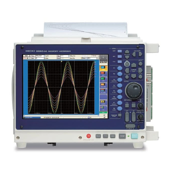
- Page 1 INSTRUCTION MANUAL 8860 8861 MEMORY HiCORDER This manual describes the instrument’s functions and operations in detail, and its specifications.
-
Page 3: Table Of Contents
Contents Contents Usage Index ................1 Introduction.................3 Reading this Manual..............5 Chapter 1 Overview ___________________________________ 7 Product Overview ..............7 Features ................7 Interconnection and Block Diagrams ........ 10 Chapter 2 Operating Keys and Screen Contents __________ 13 Operating Keys ..............13 Screen Organization ............17 Opening Screen .............. - Page 4 Contents Chapter 3 Operation Overview _________________________ 51 Measurement Workflow ............ 51 3.1.1 Analog Waveform Recording ..........51 3.1.2 Logic Waveform Recording ............ 55 Before Operating .............. 56 3.2.1 Preliminary Settings and Verification ........56 3.2.2 Using a Mouse ............... 57 3.2.3 Using a Keyboard ..............
- Page 5 Contents Adding Comments ............112 5.2.1 Adding a Title Comment ............112 5.2.2 Adding Channel Comments ..........113 Monitoring Input Status ........... 116 5.3.1 Verifying the Input Level (Level Monitor) ......116 Converting Input Values (Scaling Function) ....117 Verifying and Setting All Channels from a List ....123 Copying Settings Between Channels ......
- Page 6 Contents Chapter 7 Waveform Display Settings __________________ 163 Making Input Waveform Display Settings (Analog Waveforms) ............164 7.1.1 Setting Whether a Waveform is Displayed or Hidden, and its Color ................. 165 7.1.2 Setting the Waveform Display Position (Zero Position) ..166 Setting the Screen Layout of the Waveform Screen (Sheet Settings Screen) ..........
- Page 7 Contents 8.9.3 Magnifying a Section of the Horizontal Axis (Time Axis – Zoom Function) ..........206 8.9.4 Setting Arbitrary Waveform Height and Position on the Vertical (Voltage) Axis (Variable Function) ......208 8.10 Fine Adjustment of Input Values (Vernier Function) ..211 8.11 Viewing Past Waveforms ..........212 8.12 Viewing Waveforms in Every Display Block (Memory Division) ............
- Page 8 Contents 10.3.6 Saving Settings Data ............265 10.3.7 Automatically Saving Waveforms ........267 10.3.8 Optionally Selecting Waveforms & Saving (SAVE Key) ..270 10.3.9 Automatically Saving Display Images ........272 10.3.10Optionally Selecting Display Screens & Saving (SAVE Key) 274 10.4 Loading Data ..............275 10.4.1 Selecting Files &...
- Page 9 Contents 11.7 Print Examples ..............323 Chapter 12 System Environment Settings _______________ 333 12.1 Making Waveform Screen Display Settings ....334 12.1.1 Selecting the Grid Type ............334 12.1.2 Displaying or Hiding Comments ...........335 12.1.3 Selecting the Time Value Display .........336 12.1.4 Displaying Zero Position ............336 12.2 Making Key Operation and Operational Settings ....
- Page 10 viii Contents 13.4 Performing Remote Operations on the Instrument from an Internet Browser (Web Server) ........374 13.4.1 Making Settings on the Instrument ........374 13.4.2 Operate on the PC ............... 376 13.5 Using an Interface Card ..........380 13.6 Controlling the Instrument with Command Communications .............
- Page 11 Contents Appendix 2.1 List of Default Settings ............... A 8 Appendix 2.2 Waveform File Sizes ..............A 19 Appendix 2.3 Timebase and Maximum Recordable Time ......A 32 Appendix 2.4 Memory Capacity and Maximum Recording Length ....A 37 Appendix 2.5 Recording Length and Maximum Number of Divisions (Memory Division function) ............
- Page 12 Contents...
-
Page 13: Contents 1
Usage Index Usage Index Product Description Measurement Workflow and ⇒ "3.1 Measurement Workflow" ( p. 51) Overview ⇒ Using the Operating Keys "2.1 Operating Keys" ( p. 13) ⇒ "3.2.2 Using a Mouse" ( p. 57) ⇒ Using a Mouse and Keyboard "3.3.4 Mouse Operations"... - Page 14 Usage Index Analyzing Data ⇒ Viewing Measurement Values "8.8 Cursor Values" ( p. 195) ⇒ Saving and Loading Data "Chapter 10 Saving/Loading Data & Managing Files" ( p. 243) ⇒ Printing Data "Chapter 11 Printing" ( p. 297) Communicating with this Instru- ⇒...
-
Page 15: Introduction
Introduction Introduction In this manual, “the instrument” means the Model 8860 or 8861 Memory HiCorder. The following documents are provided with this instrument. Refer to them as appropriate for your application. Document Description Read this first. Quick Start Manual It describes preparations for use, basic operating pro- cedures and usage methods. - Page 16 Introduction Symbols and Indicators in This Manual The following symbols in this manual indicate the relative importance of cautions and warnings. Indicates that incorrect operation presents an extreme hazard that could result in serious injury or death to the user. Indicates that incorrect operation presents a significant hazard that could result in serious injury or death to the user.
-
Page 17: Reading This Manual
Reading this Manual Reading this Manual Operating Procedure Description Setting procedure overview Selectable functions Screen opening procedure See "2.2 Screen Organization" ⇒ p. 17) Settings screen Selection choices F keys (F1 to F8) selections Helpful suggestions, setting details and precautions Operating keys Although the instrument can be operated with a mouse, most of the operating descriptions in... - Page 18 Reading this Manual...
-
Page 19: Chapter 1 Overview
Various measurements including voltage, current, temperature and frequency are available using connection cables or sensors with optional input modules. Up to four input modules can be installed in the Model 8860, and up to eight in the 8861. Also, optional storage memory can be installed to enable long-term recording with high-speed sampling. -
Page 20: Appendix 2 Reference
80) About FFT Function: Analysis Supplement High capacity memory choices 8860: Choose from 32 to 128 MWords, 512 MWords or 1 GWord. 8861: Choose from 64 to 256 MWords, or 1 or 2 GWords. Plenty of trigger functions Digital triggering circuitry is employed. - Page 21 1.2 Features Search function You can find various characteristics in any measured data by specifying search criteria. ⇒ "8.14 Searching a Waveform" ( p. 215) Enhanced operability provided by GUI and support for a mouse or keyboard Operable using a commonly available mouse or keyboard. GUI screen displays are optimized to simplify both key operations and settings.
-
Page 22: Interconnection And Block Diagrams
Model 9715-02 Memory Board* (512MB) (for Model 8995)* Model 9715-03 Memory Board* (1GB) 8995-01 A6 Printer Unit (internal) (Model 8860: 1 board, Model 8861: 2 boards) 9234 Recording Paper Operation (for Model 8995-01)* ⇒ PS/2, USB Mouse ( p. 57) ⇒... -
Page 23: Internal Block Diagram
1.3 Interconnection and Block Diagrams Internal Block Diagram LOGIC(CH) Logic Probes A Monitor LOGIC(CH) Logic Probes Output Mouse Jack Isolation UNIT1-1 Device UNIT1-2 Keyboard Storage Jack Control USB Port Isolation Storage UNIT4-2 Device Memory (max. 1 GWord) Storage Bus 8861 Operating Key Control Bridge... - Page 24 1.3 Interconnection and Block Diagrams...
-
Page 25: Operating Keys And Screen Contents
2.1 Operating Keys Operating Keys and Screen Chapter 2 Contents 2.1 Operating Keys ⇒ Selects screens ( p. 14) ⇒ Selects setting choices and character entry ( p. 15) ⇒ Scrolls waveforms ( p. 15) ⇒ Sets A/B cursors ( p. - Page 26 2.1 Operating Keys MENU (Screen Select) DISP key Displays the Waveform screen showing recorded data. (Setting choices can also be changed from the Waveform screen) ⇒ "2.4 Waveform Screen" ( p. 19) When using A/B cursors or calculation functions, waveforms and numerical values can be displayed on the same screen.
- Page 27 2.1 Operating Keys Setting and Selecting (Selecting setting choices and entering charac- ters) ⇒ "3.3.3 Entering Text and Numbers" ( p. 64) ESC key Removes the displayed dialog or virtual keyboard. SELECT key When the cursor is on a setting item: opens a pull-down menu. When the cursor is on a character entry item: opens the virtual key- board for character entry.
- Page 28 2.1 Operating Keys Input Waveform Settings ⇒ "5.7 Setting Input Channels from the Waveform Screen" ( p. 128) ⇒ "5.1 Analog Channel Settings" ( p. 110) UNIT key Selects a Unit (module) (Waveform or Channel Settings screen). CH key Select a channel (Waveform or Channel Settings screen). RANGE/POSN Sets the measurement range of the input channels, waveform display knobs...
-
Page 29: Screen Organization
2.2 Screen Organization 2.2 Screen Organization There are five general screen types. Press the operating keys shown at the right to select a screen. Screen Operating Key Screen Contents This screen appears first after power on. When you turn the ⇒... -
Page 30: Opening Screen
2.3 Opening Screen 2.3 Opening Screen This screen appears first after power on. (When you turn the power off with the Waveform screen dis- played, it reappears after this screen.) The boot process takes about 40 seconds. Select a function with the F keys to F8). -
Page 31: Waveform Screen
2.4 Waveform Screen 2.4 Waveform Screen Parts of the displayed screen depend on the selected operating function. Refer to the Analysis Supplement for details of the FFT function. To open the Waveform screen Displays acquired data as waveforms or DISP Press the numerical values. - Page 32 2.4 Waveform Screen Viewing Recording Data Data acquired by the instrument is displayed as waveforms or numerical values. Waveform Display Trigger Mark Cursor Values Trigger Event Position "8.8 Cursor Values" ⇒ p. 195) Unit (Module) and Channel Nos. Trigger Level 1-1: Unit 1 –...
- Page 33 2.4 Waveform Screen Setting Items and Choices Current setting choices are displayed. To change a setting: Use the CURSOR keys to move the cursor to the setting item, and select your choice by the corresponding F key. ⇒ "3.3.2 To Change a Setting" ( p.
- Page 34 2.4 Waveform Screen Numerical Calculation Settings (only with Memory Function) [Num Calc] "Chapter 1 Numerical Calculation Functions" in the Analysis Supplement (Changes do not affect the measurement currently in progress) Numerical Calculation Execution Button Calculation Type Setting Item Group No. of Nu- Category merical Calculation Switch with the...
-
Page 35: Status Bar
2.4 Waveform Screen Status Bar Shows the processing status and various information about the current status of the instrument. Trigger Info Setting Info Internal Processing State Display Sheet Appears when setting Auto Save, Indicates the type and number Auto Print and A/B Cursors. of the displayed Sheet. - Page 36 2.4 Waveform Screen Internal and External Connection Status Appears at the lower right when a peripheral device is connected or installed. Internal Storage Media (when internal drive Model PC card PC card 9716 FD Drive 9718 HD Unit or (Slot 1) (Slot 2) 9717 MO Unit is installed) Internal Printer...
- Page 37 2.4 Waveform Screen Function Modes and Settings Pressing the FUNCTION MODE key alters the functions of the F keys. "8.4 Displaying Measured Values and In- Key-lock ⇒ formation" ( p. 189) ⇒ "8.5 Applying Gauges" ( p. 191) Backlight saver "8.6 Monitoring Input Levels (Level ⇒...
-
Page 38: Settings Screen
2.5 Settings Screen 2.5 Settings Screen Parts of the displayed screen depend on the selected operating function. Refer to the Analysis Supplement for details of the FFT function and calculation function. To open the Settings screen (The Settings screen appears.) Press the key. -
Page 39: Status Settings Screen
2.5 Settings Screen 2.5.1 Status Settings Screen To open the Status Settings screen Press the key. (The Settings screen appears.) (When using the Memory Function) SHEET/PAGE Press the keys to select a page. Basic Settings: [Basic] page Settings for Used Channels: [Use Ch] page SUB MENU... - Page 40 2.5 Settings Screen [Basic] Page (Recorder Function) Set the timebase (horizontal axis) and recording length (recording duration). Timebase and Sampling Rate Settings Set the timebase (horizontal Recording Length axis) and sampling rate Settings ⇒ p. 89). Set the recording length ⇒...
- Page 41 2.5 Settings Screen [Basic] Page (FFT Function) Make settings here for FFT analysis. Input Data Selection Select whether FFT analysis is to be applied to newly ac- quired data, or to a pre-existing waveform (Memory wave- form). Frequency Range and Number of Calculation Peak Value Display Points...
-
Page 42: Channel Settings Screen
2.5 Settings Screen 2.5.2 Channel Settings Screen To open the Channel Settings screen (The Settings screen appears.) Press the key. SHEET/PAGE Press the keys to select a page. Analog Channel Settings: [One Ch] page ⇒ Logic Channel Settings: [Logic] page ( p. - Page 43 2.5 Settings Screen [Comment] Page Displays a list of comments. Settings can be changed and copied between channels. Title The title can be included on ⇒ printouts. ( p. 112) Logic Channel Analog Channel ⇒ ⇒ Comments ( p. 113) Comments ( p.
- Page 44 2.5 Settings Screen [Variable] Page Shows the list of variable function settings for analog channels. Entries can be changed, and copied from one channel to another. Variable Function Settings List Waveform position and mag- nification on the vertical axis can be freely set. The variable function can be set on or off for each channel.
-
Page 45: Trigger Settings Screen
Analog waveform trigger settings: [Analog] page* Logic waveform trigger settings: [Logic] page (*[Analog 1 - 4] with Model 8860, or [Analog 1 - 4] [Analog 5 - 8] with Model 8861) SUB MENU Press the keys to select the menu item. -
Page 46: Sheet Settings Screen
2.5 Settings Screen 2.5.4 Sheet Settings Screen To open the Sheet Settings screen Displayed page contents depend on the selected function. Press the key. (The Settings screen appears.) SHEET/PAGE Press the keys to select a page. Analog waveform display settings: [Analog] page Logic waveform display settings:... -
Page 47: Memory Division Settings Screen
2.5 Settings Screen 2.5.5 Memory Division Settings Screen To open the Mem Div Settings screen (Memory Function only) Press the key. (The Settings screen appears.) SUB MENU Press the keys to select the menu item. Partitions internal memory space into multiple blocks. Recording Length Setting Display Block and Refer- Set the length (recording dura-... -
Page 48: Numerical Calculation (Num Calc) Settings Screen
2.5 Settings Screen 2.5.6 Numerical Calculation (Num Calc) Settings Screen To open the Num Calc Settings screen (Memory Function only) Press the key. (The Settings screen appears.) Refer to the Analysis Supplement for details of the Numerical calculation. SUB MENU Press the keys to select the... -
Page 49: Waveform Calculation (Wave Calc) Settings Screen
2.5 Settings Screen 2.5.7 Waveform Calculation (Wave Calc) Settings Screen To open the Wave Calc Settings screen (Memory Function only) Press the key. (The Settings screen appears.) Refer to the Analysis Supplement for details of the Waveform calculation. SUB MENU Press the keys to select the... -
Page 50: Save Settings Screen
2.5 Settings Screen 2.5.8 Save Settings Screen To open the Save Settings screen (The Settings screen appears.) Press the key. SHEET/PAGE Press the keys to select a page. Automatic saving: [Auto Save] page Manual saving: [SAVE Key] page SUB MENU Press the keys to select the... -
Page 51: Print Settings Screen
2.5 Settings Screen 2.5.9 Print Settings Screen To open the Print Settings screen Press the key. (The Settings screen appears.) SHEET/PAGE Press the keys to select a page. Printing method and printer settings: [Printer] page Printout contents selection: [Print Items] page SUB MENU Press the... -
Page 52: File Screen
2.6 File Screen 2.6 File Screen To open the File screen FILE Press the key. (the File screen appears) SHEET/PAGE Press the keys to select a page. Move the cursor to the folder tree or file list. Load or manage the files. Operable with a mouse. - Page 53 2.6 File Screen Function Modes and Settings The display changes according to the position of the cursor on the File screen. Pressing the FUNCTION MODE key changes the functions. When the cursor is in the File List [SET] Mode When the cursor is in the Media Tree When storage media is displayed Media List Displays the subdirectories of the stor- Displays storage media in the list.
- Page 54 2.6 File Screen [FN] Mode (Common to the Folder Tree and File List) ⇒ "10.7.6 Sorting Files" ( p. 293) ⇒ "10.7.7 Limiting Display of Files" ( p. 294) ⇒ "10.7.8 Setting the Items to Display" ( p. 295) ⇒ "10.1.6 Using a Network Shared Folder"...
-
Page 55: System Screen
2.7 System Screen 2.7 System Screen Settings Menu List Settings Screen Name on This Ref. Description Menu Instrument Use this screen to configure the system environment, Wave- ⇒ Environment (Env) Settings Screen p. 43) form screen layout and operating key functions. Communication (Comm) Settings ⇒... -
Page 56: Communication (Comm) Settings Screen
2.7 System Screen 2.7.2 Communication (Comm) Settings Screen To open the Comm Settings screen SUB MENU Press the keys to select the menu item. To open from the Opening Screen F7 [System] Press the key. To open from the Waveform or SHEET/PAGE Press the keys to select... - Page 57 2.7 System Screen [File] Page The FTP settings enable access to files on the instrument from a PC. ⇒ FTP Settings ( p. 369) Perform these settings to ac- cess files on the instrument from a PC using FTP. [Web] Page The Web Server settings enable control the instrument from a browser on a PC.
-
Page 58: External Terminals (Ext Term) Settings Screen
2.7 System Screen 2.7.3 External Terminals (Ext Term) Settings Screen To open the Ext Term Settings screen To open from the Opening Screen F7 [System] Press the key. SUB MENU Press the keys To open from the Waveform or to select the menu item. -
Page 59: Setting Configuration (Setting) Screen
2.7 System Screen 2.7.4 Setting Configuration (Setting) Screen To open the Setting screen To open from the Opening Screen F7 [System] Press the key. SUB MENU Press the keys To open from the Waveform or to select the menu item. Settings screens The System screen appears. -
Page 60: Initialization (Init) Settings Screen
2.7 System Screen 2.7.5 Initialization (Init) Settings Screen To open the Init Settings screen To open from the Opening Screen F7 [System] Press the key. SUB MENU Press the keys To open from the Waveform or Settings screens to select the menu item. -
Page 61: Configuration List (Config) Screen
2.7 System Screen 2.7.6 Configuration List (Config) Screen To open the Configuration List screen To open from the Opening Screen F7 [System] Press the key. SUB MENU Press the keys To open from the Waveform or to select the menu item. Settings screens The System screen appears. - Page 62 2.7 System Screen...
-
Page 63: Chapter 3 Operation Overview
3.1 Measurement Workflow Operation Chapter 3 Overview 3.1 Measurement Workflow 3.1.1 Analog Waveform Recording Refer to "Appendix 2.1 List of Default Settings" (⇒ p. A8) for default settings. The default setting for Auto Save and Auto Print is Off (disabled). Set the items indicated by white text within the boxes as needed. - Page 64 3.1 Measurement Workflow Measurement Make settings on the Status Settings screen. ⇒ p. 79) Configuration Settings* ⇒ ⇒ p. 85) Select Channels to Use • Memory capacity and recording time ( p. A37) ⇒ • To measure with two sampling rates ( p.
- Page 65 3.1 Measurement Workflow ⇒ Display Sheet Settings* Set on the Sheet Settings screen ( p. 168). (Make these settings to change the Waveform Screen Layout Settings (⇒ p. 171) screen layout) • To optionally assign measurement data to Sheets Split-Screen Number and Pattern Settings ⇒...
- Page 66 3.1 Measurement Workflow Press the key to save (Manual save). SAVE Optionally Save and Print Press the key to print (Manual print). PRINT Remove the cables from the measurement Power Off object, and turn the power off. Waveform data is erased when power is turned off. However, measurement settings are retained.
-
Page 67: Logic Waveform Recording
3.1 Measurement Workflow 3.1.2 Logic Waveform Recording To simultaneously record logic waveforms, see also "3.1.1 Analog Waveform Recording" (⇒ p. 51). Procedure (asterisks (*) indicate settings that can be changed while measuring) Overview and references Installation & Connection Connect the logic probes. "2.6 Connecting Logic Probes"... -
Page 68: Before Operating
3.2 Before Operating 3.2 Before Operating 3.2.1 Preliminary Settings and Verification Setting the Clock Verify that the instrument’s clock is set correctly, as it is required when applying timer triggers (⇒ p. 156) and when you need to know when a trigger was applied (⇒... -
Page 69: Using A Mouse
3.2 Before Operating 3.2.2 Using a Mouse You can connect a commonly available mouse to the instrument to perform the same operations as the keys. Mouse operating procedures: ⇒ "3.3.4 Mouse Operations" ( p. 68) Compatible Mouse Types • USB Mouse •... -
Page 70: Using A Keyboard
3.2 Before Operating 3.2.3 Using a Keyboard You can connect a commonly available keyboard to the instrument to enter char- acters directly. Entry methods: ⇒ "Using a Keyboard" ( p. 63) Compatible Keyboard Types • USB Keyboard • PS/2 Keyboard Before Connecting to the Instrument •... -
Page 71: If The Model 9719 Memory Backup Unit Is Installed
8860 8861 With Model 9715-03 Memory Board At least At least (Model 8860: 1 board, Model 8861: 2 boards) 10 hours 5 hours Smaller memory capacity permits longer backup time. Charging State An indicator shows the charging state at the lower right of the screen. -
Page 72: If The Model 9684 Dc Power Unit Is Installed
Adds approx. 29 mm (D) (1.14”D) to dimensions of Models Dimensions 8860/8861 Adds approx. 1.25 kg (44.1 oz.) to the weight of Models Mass 8860/8861 Model 8860 Serial Nos. 051040422 and above Supported Models Model 8861 Serial Nos. 051040432 and above... -
Page 73: Connection Procedure
If this occurs, turn the switch on the Power Unit off for about one minute, and then back on. Battery Operating Time (Nominal values at normal room temperature) Battery used: 12 V, 38 Ah, fully charged 8860 8861 Model 8936 Model 8956 Model 8936... -
Page 74: Common Operations
3.3 Common Operations 3.3 Common Operations 3.3.1 Select a Function The function can be selected on the Waveform or Settings screen. Move the cursor to the Function menu. Select the appropri- ate function. You can also press the SELECT key and select the function from the pull- ⇒... -
Page 75: Appendix 2.8 Keyboard Assignment Table
3.3 Common Operations Selecting from a pull-down menu Move the cursor to the setting item, and set as follows: Opens the pull-down SELECT menu. CURSOR keys Select the desired set- ting choice. ENTER Accepts the new setting. (The SELECT key also Pull-Down Menu accepts the setting) Using a Mouse... -
Page 76: Entering Text And Numbers
3.3 Common Operations 3.3.3 Entering Text and Numbers Move the cursor to the setting item for which to enter text or numbers, and press the F keys to select your setting choice. Entering Numbers Use the CURSOR keys to move the cursor to the setting item. (When using a mouse, double click on a setting item to display the virtual key- pad.) Select an input method from the F key choices. - Page 77 3.3 Common Operations Entry by [Pushwheel] (To Set Each Digit) Enter a numerical value using the virtual pushwheel switches. Press the CURSOR keys to move among digits, and press CURSOR keys to set the numerical value. Operating Buttons Accepts Entry Digits Cancels Entry Move to a digit to be entered ..
- Page 78 3.3 Common Operations Using [Edit] for Entry ⇒ "Comment Entry Example" ( p. 114) Enter text using the virtual keyboard for character entry. You can switch between character sets by switching the entry mode. To enter using a mouse, click a character to select it, or click an operating button.
- Page 79 3.3 Common Operations Virtual Keyboard Entry Modes Parts of the display differ according to entry position. [Text] [Symbols] [List/History] Previously entered comments and lists of measurement units are displayed. The display depends on the current entry position. New entries appear in empty rows as they are added to the history, and when all rows are full, the oldest entry is overwritten.
-
Page 80: Mouse Operations
3.3 Common Operations 3.3.4 Mouse Operations Operations on the Waveform Screen Switching Functions and Screens Changing Settings Select the appropriate function. Click Click Click Click Settings Screen Select by clicking Settings Screen System Screen buttons. Opening Screen File Screen The selected screen appears Changing Setting Items Controlling the Instrument Click... - Page 81 3.3 Common Operations Operations on Waveform Data Moving the A/B cursors Select the area to zoom Right Click Click Right click at the point where you want to move the cursor, then se- With zoom display enabled, lect. clicking on a location causes it to appear zoomed in the lower The A/B cursors can be moved by half of the display.
- Page 82 3.3 Common Operations Operations on the Settings Screens Switching Screens and Switching Functions Entering Text Pages Click Click Double Click Select the appro- priate function. Click Click Displays the System screen. Select and enter characters by clicking Displays the Waveform screen. buttons on the virtual keyboard.
- Page 83 3.3 Common Operations Pages within the Settings Screen Making Dialog Settings Settings Pages • All except the [One Ch] page on the Channel Settings screen • Trigger Settings screen • Sheet Settings screen • Numerical Calculation Settings screen Double Click Making Copy Settings Settings Pages •...
- Page 84 3.3 Common Operations Operations on the File Screen Icon Operations Sorting setting Delete Customize file display Rename Customize displayed item Create Folder Print file list Select All Create a network share connection Cancel All Disconnect network share Load Select/Deselect Save Refresh Move to specified destination Copy to specified destination...
-
Page 85: Automatic Range Setting (Auto-Ranging Function)
3.3 Common Operations 3.3.5 Automatic Range Setting (Auto-Ranging Func- tion) Auto setup works only with the Memory function. By applying an input signal, the timebase, measurement range and zero position of the input waveform are set automatically. The range is determined for each channel that has its waveform enabled [On] for measuring. - Page 86 3.3 Common Operations When measuring using the auto-ranging function, only the following items are changed. Basic Setting Conditions (Status Settings screen) Setting Choice Auto Setup Timebase* Auto setting value (x 1 time axis magnification) If the input signal frequency is below 3 Hz, the timebase cannot be set automatically. * Among the channels with waveforms enabled, if the measurement range of the lowest- number channel is 5 mV/div (the highest sensitivity range), or if the difference between the maximum and minimum value of the input signal is eight divisions or less, the time-...
-
Page 87: Starting And Stopping Measurement
3.3 Common Operations 3.3.6 Starting and Stopping Measurement Starting Measurement Press the START/MARK key. The green LED at the left lights. Start Measurement When measuring using the trigger functions, the timing of starting measurement is different than that of starting recording (data acquisition). ⇒... - Page 88 3.3 Common Operations Measurement and Internal Operations _____________________________ Measurement methods are normal measurement (start recording when mea- surement starts) and trigger measurement (start recording when trigger criteria are satisfied). In this manual, “Measurement start” means the instant when you press the START key, and “Recording start”...
-
Page 89: Disabling Key Operations (Key-Lock Function)
3.3 Common Operations 3.3.7 Disabling Key Operations (Key-Lock Func- tion) All operating keys on the front panel are disabled. This can prevent unintended operations during measurement. The External I/O terminals are unaffected by the key-lock state. Disabling key operation Hold both CURSOR keys simultaneously for three seconds. - Page 90 3.3 Common Operations...
-
Page 91: Measurement Configuration Settings
Measurement Configuration Chapter 4 Settings Basic measurement configuration settings are performed on the Status Settings screen. Measurement configuration can be performed from the Waveform screen (⇒ p. 108). Open the Settings screen Menu selection Page selection About screen contents: ⇒ "2.5.1 Status Settings Screen"... -
Page 92: Selecting The Function
4.1 Selecting the Function 4.1 Selecting the Function Select the function appropriate for your recording purpose. Function selection can be made from the Opening, Waveform or Settings screens. ⇒ "Choosing the Appropriate Function" ( p. 81) Function Selection: Opening Screen Operating Key Procedure Opening Screen... - Page 93 4.1 Selecting the Function Choosing the Appropriate Function The acquisition procedure and setting choices for measurement data and available operations depend on the selected operating function. Function Description This function is most suitable for oscilloscope-type measurements, such as Memory Function instantaneous waveforms and transient phenomena.
- Page 94 4.1 Selecting the Function Function Description Real-Time Saving Recommended for long-term measurements such as those that exceed the Function instrument’s internal storage capacity. Measurements are recorded directly onto storage media as a data recorder. Input One hundred data samples per division are stored directly to the internal hard drive, MO Conversion drive or PC Card while measuring.
- Page 95 4.1 Selecting the Function Function Comparison Table • − : Available, : Not available Function Items 5 µs/div to 5 min/div μ Sampling rate: 1/100 of the 10 ms/div to 1 hour/div s/div to 5 min/div timebase Sampling rate: 100 ns to 1 s (Limited by the save desti- −...
- Page 96 4.1 Selecting the Function Function-Related Recording Capabilities Memory function , Recorder function, FFT function Storage Media HDD USB NETWORK Waveform files Input signal Recording xxxx.MEM (Memory function waveform data) Display xxxx.REC (Recorder function waveform data) (Instrument’s internal memory) xxxx.FFT (FFT function data) Text file xxxx.TXT (Text data) Index file...
-
Page 97: Setting Measurement Configuration (Status Settings Screen)
4.2 Setting Measurement Configuration (Status Settings Screen) 4.2 Setting Measurement Configuration (Status Settings Screen) Make basic settings for measurement such as timebase and recording length on the Status Settings screen. These settings can also be made on the Waveform screen (⇒ p. 108). Choices of setting items are function-dependent. - Page 98 4.2 Setting Measurement Configuration (Status Settings Screen) Setting Channels to Use: Using input modules other than the Model 8958 16-Ch Scanner Unit → → SUB MENU To open the screen: Press the Select with the keys Status Settings screen ⇒ ⇒...
- Page 99 All eight Units [On] [On] 10,000 * Model 8860: 32 MWords, Model 8861: 64 MWords memory installed If “Too many measurement channels” appears You have tried to use more channels than the number enabled for use. Either increase the number of channels to use, or turn unneeded channels [Off].
- Page 100 [8 × 8CH + L] to use the maximum number of Model 8958 16-Ch Scanner Unit channels (four 8958s in the Model 8860, or eight in the 8861). In this case, the maximum recording length is halved. If “Too many measurement channels” appears You have tried to use more channels than the number enabled for use.
-
Page 101: Setting The Timebase (Horizontal Axis) And Sampling Rate
4.2 Setting Measurement Configuration (Status Settings Screen) 4.2.2 Setting the Timebase (Horizontal Axis) and Sam- pling Rate About timebase and sampling setting The timebase setting establishes the rate of input signal waveform acquisition, specified as time-per-division on the horizontal axis (time/div). The sampling setting specifies the interval from one sample to the next. - Page 102 4.2 Setting Measurement Configuration (Status Settings Screen) The data refresh rate is not allowed to exceed the maximum sampling rate of the input module. Example: Using an input module with maximum sampling rate of 1 MS/s (up to 1M samples per second). 1 MS/s = 1 µs/S (1 µs sampling period) When the [Sampling Speed] is set to...
-
Page 103: Appendix 4.4 Recorder Function Values
4.2 Setting Measurement Configuration (Status Settings Screen) Timebase and Sampling Rate Settings: Using the Operating Keys → → SUB MENU To open the screen: Press the Select with the keys Status Settings screen ⇒ ⇒ Screen Layout ( p. 27), To set from the Waveform screen ( p. -
Page 104: Setting Different Sampling Rates
4.2 Setting Measurement Configuration (Status Settings Screen) Description Measuring with the Recorder Function • When the following timebase values are selected, displayed waveforms are compressed in the horizontal (time axis) direction as shown. 50 ms/div → x1/2, 20 ms/div → x1/5, 10 ms/div → x1/10 •... - Page 105 4.2 Setting Measurement Configuration (Status Settings Screen) Setting Timebase 1 and 2: Using input modules other than the Model 8958 16-Ch Scanner Unit → → SUB MENU To open the screen: Press the Select with the keys Status Settings screen ⇒...
- Page 106 4.2 Setting Measurement Configuration (Status Settings Screen) Setting Timebase 1 and 2: When using the Model 8958 16- Ch Scanner Unit together with other input modules → → SUB MENU To open the screen: Press the Select with the keys Status Settings screen ⇒...
-
Page 107: Setting The Recording Length (Number Of Divisions)
4.2 Setting Measurement Configuration (Status Settings Screen) 4.2.4 Setting the Recording Length (number of divi- sions) Set the length (number of divisions) to record each time data is acquired. The following methods and settings are available: • Fixed recording length [Fixed]: select from the fixed recording lengths (⇒... - Page 108 200000, 500000, 1000000, 2000000, 5000000, 10000000 The setting range depends on the capacity of installed memory and the number of channels enabled for use. Maximum Recording Length [Divisions] Installed Memory No. of Chs Used (Words) 8860 8861 20,000 20,000 50,000 100,000 200,000 128M...
- Page 109 1 to 10,240,000 (divisions) The setting range depends on the capacity of installed memory and the number of channels in use. Maximum Recording Length [Divisions] Installed Memory No. of Chs Used (Words) 8860 8861 20,000 40,000 80,000 160,000 320,000 128M...
- Page 110 4.2 Setting Measurement Configuration (Status Settings Screen) Setting Continuous Recording (Cont) → → SUB MENU To open the screen: Press the Select with the keys Status Settings screen ⇒ ⇒ Screen Layout ( p. 27), To set from the Waveform screen ( p.
-
Page 111: Acquiring Waveforms Using The Utility Functions
4.3 Acquiring Waveforms Using the Utility Functions 4.3 Acquiring Waveforms Using the Utility Functions Several utility functions can be applied when acquiring data. Select from the [Utility Function] setting column on the Status Settings screen. Make these settings before measuring. Operating Utility Function Ref. - Page 112 4.3 Acquiring Waveforms Using the Utility Functions Description When the Roll Mode is enabled ([On] or [Auto]) • The Roll Mode and Overlay (⇒ p. 101) functions cannot both be enabled at the same time. When the Roll Mode is enabled, the Overlay function is auto- matically set [Off].
-
Page 113: Overlaying Waveforms
4.3 Acquiring Waveforms Using the Utility Functions 4.3.2 Overlaying Waveforms This applies to the Memory function only. Displayed waveforms are retained on-screen and overlaid with new waveforms. Use this to compare new waveforms with those recorded immediately before. (When the trigger mode is [Repeat] or [Auto]) Methods are available to automatically overlay waveforms while measuring, and... - Page 114 4.3 Acquiring Waveforms Using the Utility Functions Manual Overlay (Any waveform can be retained on-screen) → DISP To open the screen: Press the Waveform screen Operating Key Procedure CURSOR Move the cursor to the [Overlay] button. Select either choice. F1 to F8 Overlay Acquired waveforms remain on-screen.
-
Page 115: Dividing Memory
4.3 Acquiring Waveforms Using the Utility Functions 4.3.3 Dividing Memory Settings are made on the Memory Division Settings screen. Blocks to be displayed can also be selected on the Waveform screen (⇒ p. 213). This applies to the Memory function only. Open the Settings screen Menu selection About screen contents:... - Page 116 4.3 Acquiring Waveforms Using the Utility Functions Memory Division: Recording Settings → → SUB MENU To open the screen: Press the Select with the keys Mem Div Settings screen ⇒ Screen Layout ( p. 35) Operating Key Procedure Enable the Memory Division function. CURSOR Move the cursor to the [Memory Div]...
- Page 117 4.3 Acquiring Waveforms Using the Utility Functions Memory Division: Display Settings → → SUB MENU To open the screen: Press the Select with the keys Mem Div Settings screen ⇒ ⇒ Screen Layout ( p. 35), To set from the Waveform screen p.
- Page 118 4.3 Acquiring Waveforms Using the Utility Functions Getting Details on Each Block The trigger time and measurement status of each block can be viewed on the [List] screen. F2 [List]. Select Block No. A block can be selected by the CURSOR keys or the keys.
- Page 119 4.3 Acquiring Waveforms Using the Utility Functions • The times during which sampling is inhibited (dead time) due to display and recording processing after each block of data has been acquired are about 8 • When measuring a parameter other than voltage or current with the Model 8940 F/V Unit, dead time is about 230 ms.
-
Page 120: Setting Measurement Configuration On The Waveform Screen
4.4 Setting Measurement Configuration on the Waveform Screen 4.4 Setting Measurement Configuration on the Waveform Screen The following measurement configuration settings can be made on the Wave- form screen. These can be changed while measuring. • Timebase and recording length of the Status Settings screen •... -
Page 121: Input Channel Settings
Input Channel Chapter 5 Settings Set the measurement range, scaling and input waveforms for input channels on the Channel Settings screen. Input channel settings can also be made on the Waveform screen. (⇒ p. 128) Open the Settings screen Menu selection Page selection About screen contents: ⇒... -
Page 122: Analog Channel Settings
5.1 Analog Channel Settings 5.1 Analog Channel Settings Setting choices depend on the type of input module. This section describes channel settings using the Model 8936 Analog Unit. The same setting choices are available with the following input modules: • Model 8936 Analog Unit •... - Page 123 5.1 Analog Channel Settings Operating Key Procedure Set low-pass filtering (as occasion demands) CURSOR Move the cursor to the [LPF] item. F1 to F8 Set the low-pass filter in the input module. (For Model 8936) Off, 5Hz, 500Hz, 5kHz, 100kHz Select the probe attenuation.
-
Page 124: Adding Comments
5.2 Adding Comments 5.2 Adding Comments 5.2.1 Adding a Title Comment Title comments can be printed on the recording paper. Allowed number of characters: up to 40 To print, enable the setting on the Print Settings screen. ⇒ "11.6.5 Printing Comments and Setting Data" ( p. -
Page 125: Adding Channel Comments
5.2 Adding Comments 5.2.2 Adding Channel Comments Comments added for each channel can be displayed on-screen. Comments can also be printed on recording paper. Allowed number of characters: up to 40 Make settings on either the [One Ch] page or the [Comment] page. To display comments on the Waveform screen: Enable comment display from the Environment (Env) Settings screen (Default setting: Off). - Page 126 5.2 Adding Comments Comment Entry Example ________________________________________ The virtual keyboard is used to enter comments with the operating keys or a mouse. ⇒ "Using [Edit] for Entry" ( p. 66) In this example, we enter the comment “LINE-1” in the Comments field on [One Ch] page.
- Page 127 5.2 Adding Comments Copying Comments → → → SUB MENU To open the screen: Press the Select with the keys Channel Settings screen SHEET/PAGE Select the [Comment] page with the keys ⇒ Screen Layout ( p. 31) Operating Key Procedure Open the dialog.
-
Page 128: Monitoring Input Status
5.3 Monitoring Input Status 5.3 Monitoring Input Status 5.3.1 Verifying the Input Level (Level Monitor) You can verify the input status and display range while making settings on the Channel Settings screen. This is not available while measuring. Interpreting the Display _________________________________________ [One Ch] Page of Channel Setting Screen Measurement range judgment... -
Page 129: Converting Input Values (Scaling Function)
5.4 Converting Input Values (Scaling Function) 5.4 Converting Input Values (Scaling Function) About the Scaling Use the scaling function to convert the measured voltage units output from a sensor to the physical units of the parameter being measurement. Function Hereafter, “scaling” refers to the process of numerical value conversion using the Scaling function. - Page 130 5.4 Converting Input Values (Scaling Function) Setting Scaling → → SUB MENU To open the screen: Press the Select with the keys Channel Settings screen ⇒ Screen Layout ( p. 30) Operating Key Procedure SHEET/PAGE Select the [One Ch] page. (Setting can also be done on the [Scaling] page.) ⇒...
- Page 131 5.4 Converting Input Values (Scaling Function) To verify correct scaling settings: Scaling Check Select the [Check] button. The [Scaling Check] dialog appears. When appropriate numerical values have been entered, Select the [Close] but- the converted physical value is displayed. ton to close the dialog. Verify that it is converted correctly.
- Page 132 5.4 Converting Input Values (Scaling Function) Scaling Setting Examples Using a Clamp-On Probe Example 1. Measure with the 10A range of the Model 9018-10 Clamp-On Probe and display the measured data in units of [A] (Amperes) To set automatically F1 [Clamp] Select the button.
- Page 133 5.4 Converting Input Values (Scaling Function) Using the Model 8939 or 8960 Strain Unit Example 2. Using the 20 G rated capacity and a sensor with 1000 µV/V rated output, display measured data in units of [G] For the rated capacity and rated output, consult the calibration record of the sen- sor to be used.
- Page 134 5.4 Converting Input Values (Scaling Function) When a calibration factor is stated in the sensor’s inspection records It can be incorporated in the conversion ratio setting on the [Scaling] page (⇒ p. 125) of the Channel Settings screen. Example 3. Measure using a sensor with a calibration factor of 0.001442 G / 1 ×...
-
Page 135: Verifying And Setting All Channels From A List
5.5 Verifying and Setting All Channels from a List 5.5 Verifying and Setting All Channels from a List All channel settings can be verified and changed on the following Channel screen pages. In addition, settings can be copied between channels. (⇒ p. 127) Set analog channels (⇒... - Page 136 5.5 Verifying and Setting All Channels from a List Input Channel Settings List: [All Ch] Page → → SUB MENU To open the screen: Press the Select with the keys Select the [All Ch] page SHEET/PAGE with the keys Available when using the Adjusts the zero position Model 8939 or 8960 settings of all channels at...
- Page 137 5.5 Verifying and Setting All Channels from a List To set the zero position of all channels at once: execute Preset Move the cursor to the [Preset] button, and select [Preset]. The [Zero-Position] dialog appears. The setting changes when you select any button. Reset the zero positions of all channels to the default value.
- Page 138 5.5 Verifying and Setting All Channels from a List Variable Settings List: [Variable] Page → → SUB MENU To open the screen: Press the Select with the keys Select the [Variable] page SHEET/PAGE with the keys This mark indicates settings are valid.
-
Page 139: Copying Settings Between Channels
5.6 Copying Settings Between Channels Copying Settings Between Channels Copying Channel Settings Settings can be made on the [Comment], [All Ch], [Scaling] [Variable] pages of the Channel Setting screen. Operating Key Procedure Open the dialog. CURSOR Move the cursor to the source unit (module) and channel. -
Page 140: Setting Input Channels From The Waveform Screen
5.7 Setting Input Channels from the Waveform Screen 5.7 Setting Input Channels from the Waveform Screen Input channel and Waveform display settings can be made from a channel's set- ting dialog. Setting choices are the same as on the [One Ch] page of the Channel Settings screen. -
Page 141: Chapter 6 Trigger Settings
Chapter 6 Trigger Settings Make trigger settings on the Trigger Settings screen. You can also make them on the Waveform screen (⇒ p. 161). Setting choices are function-dependent. Open the Settings screen Menu selection Page selection About screen contents: ⇒ "2.5.3 Trigger Settings Screen"... -
Page 142: About Triggering
6.1 About Triggering 6.1 About Triggering What is triggering? Triggering is the process of controlling the start and stop of recording by specific signals or conditions (criteria). When recording is started or stopped by a specific signal, we say the trigger is “applied” or “triggering occurs”. In this manual, indicates a “trigger point”, as the time at which a trigger is applied. -
Page 143: Setting Workflow
6.2 Setting Workflow 6.2 Setting Workflow Trigger settings can be made on the Trigger Settings or Waveform screen. Settings choices for each item are function-dependent. ⇒ p. 132) Set whether to continue to accept triggers after measuring. Trigger Mode Settings (function-dependent) [Single], [Repeat] or [Auto] ⇒... -
Page 144: Setting The Trigger Mode
6.3 Setting the Trigger Mode 6.3 Setting the Trigger Mode Set whether to continue to accept triggers after measuring. If all trigger sources are disabled (Off, with no trigger setting), measurement starts immediately (free-running). These settings can also be made on the Waveform screen. Trigger Mode Setting →... -
Page 145: Setting Combining Logic (And/Or) For Multiple Trigger Sources
6.4 Setting Combining Logic (AND/OR) for Multiple Trigger Sources 6.4 Setting Combining Logic (AND/OR) for Multiple Trigger Sources Analog, logic, external and timer trigger criteria can be combined by AND/OR logic to define complex trigger criteria. Trigger Source (AND/OR) Setting →... -
Page 146: Pre-Trigger Settings
6.5 Pre-Trigger Settings 6.5 Pre-Trigger Settings This applies to the Memory function and FFT function only. What is pre-triggering? By setting a portion (number of divisions or percentage) of the recording length to occur before triggering, the waveform is recorded before as well as after the trigger point. - Page 147 6.5 Pre-Trigger Settings Pre-Trigger Settings → → SUB MENU To open the screen: Press the Select with the keys Trigger Settings screen ⇒ ⇒ Screen Layout ( p. 33), To set from the Waveform screen ( p. 161) Operating Key Procedure Select the setting method (% or div) for pre-triggering.
- Page 148 6.5 Pre-Trigger Settings When using a [Stop] trigger at the same time When you want to record data from a specified moment sometime after a trigger event (that is, with a negative pre-trigger value specified), if a stop trigger event occurs after the pre-trigger period has passed but within 2 ms after recording starts, no waveform data is stored.
-
Page 149: Setting Trigger Acceptance (Trigger Priority)
6.5 Pre-Trigger Settings 6.5.2 Setting Trigger Acceptance (Trigger Priority) When pre-triggering is enabled, trigger events are normally ignored for a certain period after measurement starts (while recording the specified pre-trigger period). This period is indicated on the Status bar as [Pre-Trig Wait]. -
Page 150: Setting Trigger Timing
6.6 Setting Trigger Timing 6.6 Setting Trigger Timing Set waveform recording operation when a trigger event occurs. Timing for the Recorder function is set as follows. Timing for the Memory function can be selected by various trigger settings. Trigger Timing Setting →... - Page 151 6.6 Setting Trigger Timing Example: When the trigger type is Level Trigger, Level = 0.000 V, and Slope = ↑(rising) Trigger timing [Start] [Stop] [Start & Stop] START Records for specified Press START key to record Recording starts when a recording length Records until a trigger Start trigger event occurs...
-
Page 152: Triggering By Analog Signals
6.7 Triggering by Analog Signals 6.7 Triggering by Analog Signals 6.7.1 About Analog Trigger Types and Settings Type of Analog Trigger Trigger Example Description [ ]: Displayed on screen A trigger is applied when an in- Level Trigger put signal crosses the speci- Trigger Level [Level] fied trigger level (threshold... - Page 153 • Voltage Sag Trigger Multiple triggers can apply to one channel. Expanded Model 8860: Up to 8, Model 8861: Up to 8 for All analog triggers Unit 1 to 4, and up to 8 for Unit 5 to 8 • Triggers can be enabled for channels that are not currently selected for use (Off).
- Page 154 6.7 Triggering by Analog Signals Setting by Dialog ([Analog Trigger] dialog) Move the cursor to a trigger to set in the [No.] column, and select to open F1 [All Settings] the dialog. Move the cursor to each item, and make the setting. After making settings, select the [Close] button to accept the changes.
- Page 155 6.7 Triggering by Analog Signals When Using Noisy Signals for Triggering Enable the trigger filter (⇒ p. 145) By setting the filter width to prevent triggering on noise, triggering occurs only when the trigger criteria continue to be met for at least the specified width (inter- val).
-
Page 156: (Level Trigger)
6.7 Triggering by Analog Signals 6.7.2 Triggering When Crossing a Voltage Threshold (Level Trigger) A trigger can be applied when the input signal crosses a specified trigger level (voltage threshold). The direction in which the signal crosses the threshold is ↑... - Page 157 6.7 Triggering by Analog Signals Operating Key Procedure Set the trigger filter (as occasion demands) (⇒ p. 143). CURSOR Move the cursor to the [Filter] item. F1 to F8 Set the filter width. Trigger filtering is disabled. (default setting) 0.1 to 10 Trigger filtering is enabled.
-
Page 158: Triggering With Upper And Lower Thresholds (Window Trigger)
6.7 Triggering by Analog Signals 6.7.3 Triggering with Upper and Lower Thresholds (Window Trigger) Two types of window trigger are available: • In-Window Trigger [Win-In] Set upper and lower trigger thresholds so that triggering occurs when an input signal enters the defined range. •... -
Page 159: Triggering By Period Variance (Period Trigger)
6.7 Triggering by Analog Signals 6.7.4 Triggering by Period Variance (Period Trigger) Two types of period triggering are available: • In-Period Trigger [Peri-In] By measuring the rising and falling period at a reference voltage, apply a trig- ger when the input signal enters specified period limits. •... - Page 160 6.7 Triggering by Analog Signals Operating Key Procedure Set the trigger filter (as occasion demands) (⇒ p. 143). Set the event count (as occasion demands) (⇒ p. 143). When using the Memory function, or when using the Recorder func- tion with [Timing] set to [Start & Stop] Set the trigger to Start or Stop (⇒...
-
Page 161: Triggering By Pulse Width (Glitch Trigger)
6.7 Triggering by Analog Signals 6.7.5 Triggering by Pulse Width (Glitch Trigger) Triggering occurs when the input signal crosses the trigger level (threshold volt- age) if its pulse width is shorter than the specified width. ↑ ↓ Rising ( ) or falling ( ) edge pulse width can be selected by Trigger Slope set- ting. -
Page 162: Slope Trigger
6.7 Triggering by Analog Signals 6.7.6 Triggering by a Variance within a Specified Interval (Slope Trigger) A trigger is applied when a specified variance (slope amount) occurs within a specified time. The slope is specified by a width (time) and level (amount of ↑... - Page 163 6.7 Triggering by Analog Signals Description About the relationship between slope and trigger When the specified slope is When the specified slope is negative (–) positive (+) Width ↑ Slope Level ( Level ( ↑ Slope Width Width ↓ Slope −...
-
Page 164: Triggering Upon Instantaneous Voltage Sag At Commercial Mains Frequency (50/60 Hz) (Voltage Sag Trigger)
6.7 Triggering by Analog Signals 6.7.7 Triggering upon Instantaneous Voltage Sag at Commercial Mains Frequency (50/60 Hz) (Voltage Sag Trigger) Applicable timebase range is from 20 µs to 50 ms/division. Triggering occurs when peak voltage drops below the specified level for more than one-half cycle. -
Page 165: Triggering By Logic Signals (Logic Trigger)
6.8 Triggering by Logic Signals (Logic Trigger) 6.8 Triggering by Logic Signals (Logic Trigger) Input signals on logic channels serve as the trigger source. Triggering occurs when the specified trigger pattern and logical probe combining criteria (AND/OR) are met. The trigger detection method can be selected according to whether a trigger is applied or not when the criteria are already met at the start of measurement. - Page 166 6.8 Triggering by Logic Signals (Logic Trigger) Logic Trigger → → SUB MENU To open the screen: Press the Select with the keys Trigger Settings screen ⇒ Screen Layout ( p. 33) Logic Channels By selecting F1 [All Settings] Trigger Mark in the [Lch] column, settings This mark appears when the can be made from a dialog.
- Page 167 6.8 Triggering by Logic Signals (Logic Trigger) [Level] (Trigger source: when [AND]) Operating Key Procedure Start Measurement Select the trigger detection method. Lch A 1 CURSOR Move the cursor to the [Detect] item. Lch A 2 F1 to F8 Select either choice. Lch A 3 Level Triggering occurs when the criteria are...
-
Page 168: Trigger By Timer Or Time Intervals (Timer Trigger)
6.9 Trigger by Timer or Time Intervals (Timer Trigger) 6.9 Trigger by Timer or Time Intervals (Timer Trigger) Set this to record at fixed times. Triggering occurs at the specified interval from the specified Start time until the Stop time. Before setting, verify that the clock is set to the correct time. - Page 169 6.9 Trigger by Timer or Time Intervals (Timer Trigger) Description About start and stop times • Start and Stop times should be set as times elapsed since the START key was pressed. • When the trigger mode is [Single] and the timer trigger is [On], only one timer trigger specified as the Start trigger is recognized.
- Page 170 6.9 Trigger by Timer or Time Intervals (Timer Trigger) When a trigger is applied from a trigger source other than a timer trigger Trigger sources set to On are all enabled. However, trigger timing depends on the trigger source settings. •...
-
Page 171: Triggering Manually (Manual Trigger)
6.10 Triggering Manually (Manual Trigger) 6.10 Triggering Manually (Manual Trigger) Triggers can be applied manually. Manual triggering takes priority over all other trigger sources, regardless of settings. Manual Trigger → DISP To open the screen: Press the Waveform screen Operating Key Procedure DISP Displays the Waveform screen. -
Page 172: Applying An External Trigger (External Trigger)
6.11 Applying an External Trigger (External Trigger) 6.11 Applying an External Trigger (External Trigger) An external signal applied to the External Control terminal can serve as a trigger source. It can also be used to synchronously drive parallel triggering of multiple instruments. -
Page 173: Making Trigger Settings On The Waveform Screen
6.12 Making Trigger Settings on the Waveform Screen 6.12 Making Trigger Settings on the Waveform Screen The following trigger criteria settings can be made on the Waveform screen. Press the SUB MENU keys to select available setting items. • Trigger Mode •... - Page 174 6.12 Making Trigger Settings on the Waveform Screen...
-
Page 175: Waveform Display Settings
Waveform Chapter 7 Display Settings Waveform display, display colors and other input channel settings are made on the Channel Settings screen. The screen layout of each sheet on the Waveform screen is set on the Sheet Settings screen. Open the Settings screen Menu selection Page selection About screen contents:... -
Page 176: Making Input Waveform Display Settings (Analog Waveforms)
7.1 Making Input Waveform Display Settings (Analog Waveforms) 7.1 Making Input Waveform Display Settings (Analog Waveforms) Make settings for display of input channel waveforms in the [Wave Disp] (Waveform Display) settings on the Channel Settings screen. About Logic Waveforms "7.3 Displaying Logic ⇒... -
Page 177: Setting Whether A Waveform Is Displayed Or Hidden, And Its Color
7.1 Making Input Waveform Display Settings (Analog Waveforms) 7.1.1 Setting Whether a Waveform is Displayed or Hidden, and its Color For each channel, you can set whether a waveform is to be displayed or not. Waveform colors can be changed. The settings for analog channel are described here. -
Page 178: Setting The Waveform Display Position (Zero Position)
7.1 Making Input Waveform Display Settings (Analog Waveforms) 7.1.2 Setting the Waveform Display Position (Zero Position) Set the waveform zero position (in this example, zero volts) for display on the vertical axis. The waveform display range can be verified on the Level Monitor. Normal Waveform Changed Zero Position 100%... - Page 179 7.1 Making Input Waveform Display Settings (Analog Waveforms) Description Magnification and compression (⇒ p. 205) in the voltage axis direction is based on the zero position. Although the range of voltage that can be displayed on the Waveform screen depends on the zero position and magnification/compression of the voltage axis, the measurement range is unaffected.
-
Page 180: Setting The Screen Layout Of The Waveform Screen (Sheet Settings Screen)
7.2 Setting the Screen Layout of the Waveform Screen (Sheet Settings Screen) 7.2 Setting the Screen Layout of the Waveform Screen (Sheet Settings Screen) Set on the Sheet Settings screen. Setting choices are function-dependent. Refer to the Analysis Supplement for FFT function setting details. Select channels according to the types of waveforms to be displayed. -
Page 181: Assigning Display Data To Sheets
7.2 Setting the Screen Layout of the Waveform Screen (Sheet Settings Screen) 7.2.1 Assigning Display Data to Sheets Measurement data can be split and displayed on up to 16 sheets on the Wave- form screen. Each sheet can be assigned analog, logic, X-Y, analog & logic, analog & X-Y waveforms and numerical values. - Page 182 7.2 Setting the Screen Layout of the Waveform Screen (Sheet Settings Screen) Sheet Setting Assign four analog waveform channels and one logic waveform channel Example (four probes) to graphs on Sheet 1. [Logic] Page Sheet Settings Screen [Analog] Page Waveform Screen Press the SHEET/PAGE keys to select S1...
-
Page 183: Assigning A Sheet Name
7.2 Setting the Screen Layout of the Waveform Screen (Sheet Settings Screen) 7.2.2 Assigning a Sheet Name A name can be assigned to each sheet. The sheet name appears on the status bar of the Waveform screen. To switch sheets on the Waveform screen, press the SHEET/PAGE keys. -
Page 184: Splitting The Display Screen (Split-Screen)
7.2 Setting the Screen Layout of the Waveform Screen (Sheet Settings Screen) 7.2.4 Splitting the Display Screen (Split-Screen) The screen can be split into multiple regions (graphs). You can specify the posi- tion of each channel’s graph. (⇒ p. 174) This setting is available when any display type other than [Numeric] is selected. -
Page 185: Setting Waveform Scrolling Orientation
7.2 Setting the Screen Layout of the Waveform Screen (Sheet Settings Screen) Pattern Settings → → SUB MENU To open the screen: Press the Select with the keys Sheet Settings screen ⇒ Screen Layout ( p. 168) Operating Key Procedure When the [Waveform] display type is selected and Split- Screen is set to Graphs] or more, set the split-screen dis-... -
Page 186: Assigning Display Channels To Graphs (Analog Channels)
7.2 Setting the Screen Layout of the Waveform Screen (Sheet Settings Screen) 7.2.6 Assigning Display Channels to Graphs (Analog Channels) The default setting assigns channels in the order of input module installation. However, with the Memory function or Real-time saving function, only those channels enabled for use [On] can be assigned. - Page 187 7.2 Setting the Screen Layout of the Waveform Screen (Sheet Settings Screen) To reset, clear or re-order assignments Move the cursor to the [Reset Chs] button, and select F1 [Reset Chs]. A dialog appears. Select an item with the CURSOR keys, and press the key.
-
Page 188: Displaying Logic Waveforms
7.3 Displaying Logic Waveforms 7.3 Displaying Logic Waveforms Settings such as those for measurement configuration are the same as for ana- log waveforms. Logic Waveform Display Setting Workflow Select a measurement channel (Memory function and Real-time saving function only) [Use Ch] page on the Status Settings screen •... -
Page 189: Setting The Waveform Display
7.3 Displaying Logic Waveforms 7.3.1 Setting the Waveform Display Set whether to display or hide the waveform for each logic channel probe. Logic Waveform Display/Hide and Display Color Settings → → SUB MENU To open the screen: Press the Select with the keys Channel Settings screen... -
Page 190: Setting The Display Position
7.3 Displaying Logic Waveforms 7.3.2 Setting the Display Position The logic waveform display position can be set for each channel. When recording a mix of analog and logic waveforms, overlapping of waveforms on the display can be minimized by setting the display position and height. Logic Waveform Display Settings →... -
Page 191: Setting The Display Height
7.3 Displaying Logic Waveforms Numbering changes when changing the display position If a duplicate position number is accepted for a channel, or if another screen is displayed without accepting assignments, the position number of the duplicated channel is automatically changed. •... -
Page 192: Composite Waveforms (X-Y Waveforms)
7.4 Composite Waveforms (X-Y Waveforms) 7.4 Composite Waveforms (X-Y Waveforms) This applies to the Memory function only. Any channels can be displayed as a composite during or after measurement. To make a composite while measuring, measurement configuration settings and X- Y composite have to be set before starting measurement. - Page 193 7.4 Composite Waveforms (X-Y Waveforms) Operating Key Procedure Set whether to display or hide composite waveforms, and display color. SHEET/PAGE Select the [X-Y Comp] page. CURSOR Move the cursor to the [Col] (Color) column for the No. to be displayed. F1 to F8 Select [On]...
- Page 194 7.4 Composite Waveforms (X-Y Waveforms) Making X-Y composite settings from a dialog Move the cursor to the [No.] column to be set, and select F1 [All Settings]. A dialog appears. Move the cursor to each item and select with the F keys. To reset graph settings Move the cursor to the [Reset Graphs]...
- Page 195 7.4 Composite Waveforms (X-Y Waveforms) Method 2 View the normal waveform display together with the partial composite waveform Set the Display Type on the Sheet Settings screen to [Wave & X-Y], and set the Composite Area to [A-B]. Also make the required settings for the X-Y composite such as composite channel selections.
- Page 196 7.4 Composite Waveforms (X-Y Waveforms)
-
Page 197: Waveform Screen Monitoring And Analysis
Waveform Screen Monitoring Chapter 8 and Analysis Analytical operations such as display magnification, compression, and search are available on the Wave- form screen. Measurement configuration and related settings can also be changed. Open the Waveform screen Select the Sheet to display About screen contents: ⇒... -
Page 198: Scrolling Waveforms
8.1 Scrolling Waveforms 8.1 Scrolling Waveforms When measuring or displaying an existing waveform, use the Jog and Shuttle (SCROLL) knobs to scroll. The scrolling speed is controlled by the rotation angle of the Shuttle knob. Scroll Direction Screen Display Earlier Later Shuttle Turn CCW... -
Page 199: Verifying Waveform Display Position
8.2 Verifying Waveform Display Position 8.2 Verifying Waveform Display Position From the scroll bar you can verify the relative position and size of the displayed portion of a waveform within the overall recorded waveform. Trigger time, trigger position and A/B cursor positions (when using vertical or trace cursors) are also displayed. -
Page 200: Specifying A Display Location (Jump Function)
8.3 Specifying a Display Location (Jump Function) 8.3 Specifying a Display Location (Jump Func- tion) When the recording length of a waveform is long or when the desired portion is off-screen, you can specify the portion to be displayed immediately. This opera- tion is available with the following functions: •... -
Page 201: Displaying Measured Values And Information
8.4 Displaying Measured Values and Information 8.4 Displaying Measured Values and Informa- tion You can select the type of information (A/B cursor values, channel setting val- ues) and the gauge display method to be displayed with waveforms. If the infor- mation is obscured by overlapping waveforms, it can be displayed in a separate screen region. - Page 202 8.4 Displaying Measured Values and Information Switching Information Contents __________________________________ Displayable Contents (display details depend on operating state) Informa- AB Cursor * Ch Info Num Calc * Monitor tion Item • Analog1 • Analog • A-Comment • Logic (no info display) •...
-
Page 203: Applying Gauges
8.5 Applying Gauges 8.5 Applying Gauges Gauges corresponding to the measurement range of each channel can be dis- played at the left side of the screen. Measurement values can be verified on the gauges. Press the FUNCTION MODE key to enable the FN mode, then press [Gauge]. -
Page 204: Monitoring Input Levels (Level Monitor)
8.6 Monitoring Input Levels (Level Monitor) 8.6 Monitoring Input Levels (Level Monitor) All input waveform levels can be monitored in real time. Analog channels 1 to 8 and logic channels A to D can be displayed at the same time. Enable the FN mode by pressing the FUNCTION MODE key, then the... -
Page 205: Specifying A Waveform Range
8.7 Specifying a Waveform Range 8.7 Specifying a Waveform Range You can specify a waveform range using the A/B cursors to verify measurement values between the cursors, save and print the range, or apply it to a partial com- posite waveform. Specifying a range with the A/B cursors Select the cursor type (Vertical, Horizontal, Trace, or Off). - Page 206 The range can be within the data recorded by one measurement, or within the internally recorded data that can be retraced from the end of measurement. (see Table below) (with [ x 1] magnification) [Divisions] Installed Memory (Words) 8958 16-Ch Scanner Unit 8860 8861 When Uninstalled When Installed 5,000 1,000...
-
Page 207: Cursor Values
8.8 Cursor Values 8.8 Cursor Values Time difference, frequency and potential difference (and when scaling is enabled, scaling values) can be read as numerical values using the A/B cursors on the Waveform screen. Refer to "8.8.5 Reading Cursor Values of X-Y Wave- forms"... - Page 208 8.8 Cursor Values About Cursor Values Cursor Value Display Example Cursor Type Cursor Value (with two cursors) Time from trigger point or record- A Cursor value, B Cursor value: Time from trigger point or ing start recording start Vertical B–A value: Time difference between A/B cursors Cursors frequency having period t...
-
Page 209: Reading Time And Frequency (Vertical Cursors)
8.8 Cursor Values 8.8.2 Reading Time and Frequency (Vertical Cursors) Displays the time and frequency values at the A/B cursors, or the difference in times and frequencies between the A/B cursors. About cursor values: ⇒ "8.8.1 About Cursor Types and Values" ( p. - Page 210 8.8 Cursor Values Operating Key Procedure Move the A/B cursors and read the cursor values. A/B knobs Turn (inner) Knob A and (outer) Knob B to move the A/B cursors. Time Values Frequencies ⇒ "About Cursor Values" ( p. 196) If cursors are not visible on-screen even when enabled by the A/B Cursor settings Cursor measurements are available even when the A/B cursors are off-screen.
-
Page 211: Reading Voltage Values (Horizontal Cursors)
8.8 Cursor Values 8.8.3 Reading Voltage Values (Horizontal Cursors) Displays the voltage values at the A and B cursors for the selected channel(s), or the voltage between A/B cursors. About cursor values: ⇒ "8.8.1 About Cursor Types and Values" ( p. -
Page 212: Reading Time And Voltage Values (Trace Cursor)
8.8 Cursor Values 8.8.4 Reading Time and Voltage Values (Trace Cursor) Displays the data values at the intersections (trace points) of cursors and wave- forms. About cursor values: ⇒ "8.8.1 About Cursor Types and Values" ( p. 195) Trace Cursor Setting →... - Page 213 8.8 Cursor Values Operating Key Procedure Select the axis to serve as the origin of cursor move- ment. (Only when using the Timebase 2 with the Memory function) CURSOR Move the cursor to the [Axis] item. Select either choice. F1 to F8 Timebase 1 or Timebase 2 Select the channels for which to display cursor values.
-
Page 214: Reading Cursor Values Of X-Y Waveforms
8.8 Cursor Values 8.8.5 Reading Cursor Values of X-Y Waveforms This applies to the Memory function only. The A/B cursors can be used to read measurement values on X-Y waveforms. With split-screen display, even when the A/B cursors are set to different graphs, the potential difference between A and B can be obtained. - Page 215 8.8 Cursor Values Press the TYPE key to open the [A/B Cursor] dialog. Select the cursor type and required items. Channel The setting procedure is the same as for normal waveforms. Cursor A Cursor B "8.8.4 Reading Time and Voltage ⇒...
-
Page 216: Magnifying And Compressing Waveforms
8.9 Magnifying and Compressing Waveforms 8.9 Magnifying and Compressing Waveforms 8.9.1 Magnifying and Compressing Horizontally (Time Axis) Data details can be observed by magnifying the waveform along the time axis. Also, by compressing the time axis, overall waveform fluctuations can be readily seen. -
Page 217: Magnifying And Compressing Vertically (Voltage Axis)
8.9 Magnifying and Compressing Waveforms 8.9.2 Magnifying and Compressing Vertically (Voltage Axis) Waveforms on each channel can be magnified or compressed along the voltage axis for display or printing. Magnification and compression based on zero position (⇒ p. 166). Normal Display Magnified Display (×... -
Page 218: Magnifying A Section Of The Horizontal Axis (Time Axis - Zoom Function)
8.9 Magnifying and Compressing Waveforms 8.9.3 Magnifying a Section of the Horizontal Axis (Time Axis – Zoom Function) This applies to the Memory function and Real-time saving function only. A magnified section of a waveform can be displayed together with the unmagni- fied view by splitting the screen horizontally. - Page 219 8.9 Magnifying and Compressing Waveforms About logic waveform display Depending on display position (⇒ p. 178) and height (⇒ p. 179) settings for logic waveforms, some waveforms may not be displayed. When the Display Height is set to [Wide]: waveforms up to Display Position 2 are displayed When the Display Height is set to [Normal]: waveforms up to Display Position 4 are displayed...
-
Page 220: Setting Arbitrary Waveform Height And Position On The Vertical (Voltage) Axis (Variable Function)
8.9 Magnifying and Compressing Waveforms 8.9.4 Setting Arbitrary Waveform Height and Position on the Vertical (Voltage) Axis (Variable Function) The waveform height and display position can be arbitrarily set along the vertical axis. Precautions for using the Variable Function • Verify that the measurement range (voltage axis range) is set properly for the input signal. - Page 221 8.9 Magnifying and Compressing Waveforms Variable Function (Per-Division Setting) → → SUB MENU To open the screen: Press the Select with the keys Channel Settings screen ⇒ To set from the Variable List ( p. 126) Operating Key Procedure Enable the Variable function. CURSOR Move the cursor to the [Variable]...
- Page 222 8.9 Magnifying and Compressing Waveforms Description When setting combined use of the Scaling and Variable func- tions When Auto-Correction of the Variable function is enabled (On, default set- ting) (⇒ p. 341) The Variable function settings change according to Scaling and voltage axis range settings.
-
Page 223: Fine Adjustment Of Input Values (Vernier Function)
8.10 Fine Adjustment of Input Values (Vernier Function) 8.10 Fine Adjustment of Input Values (Vernier Function) Fine adjustment of input voltage can be performed arbitrarily on the Waveform screen. When recording physical values such as noise, temperature and accel- eration using sensors, amplitude can be adjusted to facilitate calibration. Normal Display Vernier Function Enabled 1.2 V... -
Page 224: Viewing Past Waveforms
8.11 Viewing Past Waveforms 8.11 Viewing Past Waveforms This operation is available when the Memory Division function is disabled. The instrument stores in internal memory up to 16 waveform measurements (16 blocks) that were measured with the same setting configuration (subse- quently, the data acquired during each measurement will be referred to as a “block”). -
Page 225: Viewing Waveforms In Every Display Block (Memory Division)
8.12 Viewing Waveforms in Every Display Block (Memory Division) 8.12 Viewing Waveforms in Every Display Block (Memory Division) This operation is available when the Memory Division function (⇒ p. 103) is enabled. Block usage status can be verified during Memory Division recording. In addi- tion, the waveform recorded in any block can be displayed. -
Page 226: Viewing Waveform Data As Numerical Values
8.13 Viewing Waveform Data as Numerical Values 8.13 Viewing Waveform Data as Numerical Values To display numerical values Set the Display Type on the Sheet Settings screen to [Numeric]. ⇒ "7.2.3 Setting the Display Type" ( p. 171) DISP Jog scrolls the displayed channel Shuttle scrolls the time axis... -
Page 227: Searching A Waveform
8.14 Searching a Waveform 8.14 Searching a Waveform Any location within measured waveform data that satisfies the search criteria can be found and displayed. Search criteria can be specified as trigger criteria, peaks and times. These are available only with the Memory and Real-Time Sav- ing functions. -
Page 228: Searching By Trigger Criteria
8.14 Searching a Waveform 8.14.1 Searching by Trigger Criteria Measured data can be searched using the following trigger criteria. Trigger Waveform content specifiable with this search Criteria Example criteria Search Level Level (Lvl), Slope (Slp), Filter (Flt) Win-In Upper limit (Up), Lower limit (Low), Filter (Flt) Win-Out Upper limit (Up), Lower limit (Low), Filter (Flt) Logic... - Page 229 8.14 Searching a Waveform Trigger Criteria Search → DISP To open the screen: Press the Waveform screen Operating Key Procedure Display [FN] mode. FUNCTION MODE Select [Search]. The [SEARCH] dialog box appears. Select the contents to find. CURSOR Move the cursor to the [Method] item.
- Page 230 8.14 Searching a Waveform Operating Key Procedure Setting Analog Channel Search Criteria Displayed items depend on the trigger type. When the trigger type is [Level] Select the criteria number to use. CURSOR Move the cursor to the [No.] item. F1 to F8 Select a number for this set of search criteria, from Analog 1 to Analog 8.
- Page 231 8.14 Searching a Waveform Operating Key Procedure Select ( ) [Auto Close] to have the dialog close auto- Setting Logic Channel Search Criteria matically after searching. Logic channel search criteria Trigger pattern Trigger filterÅiFilter WidthÅj Select the criteria number to use. CURSOR Move the cursor to the [No.]...
- Page 232 8.14 Searching a Waveform Description ___________________________________________________ If search results differ from expectations Undesired search results may occur as a result of noise on the acquired wave- form. In such cases, enable the trigger filter. ⇒ "6.7 Triggering by Analog Signals" ( p.
-
Page 233: Searching By Time
8.14 Searching a Waveform 8.14.2 Searching by Time You can search recorded data for a specific time. The time to search for can be specified as relative time elapsed after a trigger event, or as an absolute date and time. Time Search →... -
Page 234: Searching For Peaks
8.14 Searching a Waveform 8.14.3 Searching for Peaks You can select to search for the maximum, minimum, local maxima and local minima of recorded measurement data. Peak Search → DISP To open the screen: Press the Waveform screen Operating Key Procedure Display [FN] mode. - Page 235 8.14 Searching a Waveform Operating Key Procedure (If searching for local maxima or minima) Local maxima when the filter setting is OFF Set the criteria for the local maximum or minimum value (Filter). CURSOR Move the cursor to the [Filter] item.
- Page 236 8.14 Searching a Waveform...
-
Page 237: Measuring With Real-Time Saving
9.1 Overview of the Real-Time Saving Function Measuring with Chapter 9 Real-Time Saving 9.1 Overview of the Real-Time Saving Function The Real-Time Saving function saves data to a specified save destination while measuring. Long-term measurement is available regardless of the installed memory capacity of the instrument. - Page 238 9.1 Overview of the Real-Time Saving Function • To use the Real-Time Saving function, at least 3 MB of free space must be available on the storage media. • Measurement using different sampling rates is not available with the Real- Time Saving function.
-
Page 239: Setting And Analysis Workflow
9.2 Setting and Analysis Workflow 9.2 Setting and Analysis Workflow Function Selection Select the Real-Time Saving function. ⇒ See: "Choosing the Appropriate Function" ( p. 81) From the Initial screen: Press the F4 [REALTIME] key. Function Menu From the Waveform or Settings screen: Use the CURSOR keys to move the cursor to the function menu, and press the F4 [REAL-... - Page 240 9.2 Setting and Analysis Workflow Measurement Make settings on the Status Settings screen. Configuration Settings Measurement using different sampling rates is not available with the Real-Time Saving function. Press the key to open the Settings screen Press the SUB MENU keys to select the menu Press the...
- Page 241 9.2 Setting and Analysis Workflow Input Channel Settings Make settings on the Channel Settings screen. Press the SUB MENU keys to select the menu Press the SHEET/PAGE keys to select the [One Ch] page Select the Unit (module) and Channel Select the measurement range (vertical axis) Make input-module-related settings Perform zero adjustment...
-
Page 242: Saving Settings
9.2 Setting and Analysis Workflow End of Measurement Press the STOP key. Recording stops after acquiring the specified length (the green LED goes off). Press twice to stop immediately. Data Analysis Analysis on the waveform screen. "Chapter 8 Waveform Screen Monitoring and Analysis" ⇒... - Page 243 9.2 Setting and Analysis Workflow Printing Settings (If you want to print data) Make settings on the Print Settings screen, and Press the SUB MENU keys to select the press the PRINT key to print. menu Press the SHEET/PAGE keys to select the [Printer] page Select manual printing...
-
Page 244: Pre-Measurement Settings
9.3 Pre-Measurement Settings 9.3 Pre-Measurement Settings Make the settings required for measurement, such as the save destination and channels to use. Settings required before measurement: Save destination and channel(s) to use Because the timebase and recording length may be limited by the save destination and number of channels used, always check these settings before measuring. - Page 245 9.3 Pre-Measurement Settings Setting Recording Conditions → SUB MENU To open the screen: Select with the keys Status Settings screen Operating Key Procedure SHEET/PAGE Select the [Basic] page. Specify the save destination. CURSOR Move the cursor to the [Save in] item.
- Page 246 In this case, choose [Manual] and set the timebase for the whole waveform manually. • Model 8860 (9715) with 32 MW internal memory: at least 32 MB available space • Model 8861 (9715) with 64 MW internal memory: at least 64 MB available space •...
- Page 247 9.3 Pre-Measurement Settings Operating Key Procedure Select the recording method CURSOR Move the cursor to the [Trigger mode] item. F1 to F8 Select the setting method for the recording length. Single Record only once (default setting) Repeat Until you press the STOP key, recording Timer settings repeats at intervals of the set recording The setting procedure is the same as for...
- Page 248 9.3 Pre-Measurement Settings Starting and Ending Recording Press the START key. The green LED lights as measurement starts. After recording for the set recording length, data for the whole waveform is displayed. Measurement waveform data is saved directly to the save destination. If the trigger mode is [Single], measurement stops.
- Page 249 9.3 Pre-Measurement Settings Relationship Between the Number of Channels Used and Timebase (Real-Time Saving Function) Timebase setting may be limited by the save destination and the number of channels used. The maximum number of channels usable with each timebase setting and type of save destination is as follows.
-
Page 250: Analyzing Data
9.4 Analyzing Data 9.4 Analyzing Data 9.4.1 Waveform Viewing Three types of waveform display are available with the Real-Time Saving func- tion. • [Whole] Whole Waveform (the waveform recorded with the [Whole Wave] timebase set on the Status Settings screen) •... - Page 251 9.4 Analyzing Data Viewing Waveforms After Measurement Stops [Whole] is displayed when measurement finishes. Move the cursor to the [Disp] setting item and select F3 [All]. The whole waveform is displayed at the top, and Whole the measurement waveform at the bottom. Waveform The framed portion of the whole waveform indi- cates the currently displayed measurement wave-...
- Page 252 9.4 Analyzing Data Changing and loading the location of the displayed measurement waveform Move the cursor to the [Load] setting item, and select the location (division number) of the measurement waveform to display. The (linked) dotted-line frame in the whole waveform changes.
- Page 253 9.4 Analyzing Data Viewing Saved Waveform Data Press the FILE key to display the File screen. Select and load an index file (.RSI) created by the Real-Time Saving function. CURSOR File Selection: keys → Loading: [Load] key (Page 1/3) [Execute] ⇒...
-
Page 254: Calculating
9.4 Analyzing Data 9.4.2 Calculating Data recorded with the Real-Time Saving function can be subjected to numerical value calculations, waveform calculations and FFT analysis. In all cases, load the index file (.RSI) created by the Real-Time Saving function, display (load) the measurement waveform area to be used for calculation, and select the desired function. -
Page 255: Saving/Loading Data & Managing Files
Saving/Loading Data & Chapter 10 Managing Files Data can be saved and loaded and files can be managed. Before saving data, configure the save settings on the Save Settings screen. Load data and manage files from the File screen. Open the Settings screen Menu selection Page selection Open the File Screen... -
Page 256: Storage Media
Before saving or loading data to/from a PC card, insert the PC card in the PC card slot on the right side of the instrument. (Two slots are available.) Supported PC Cards Hioki options PC cards (includes adapter) • 9626 PC Card 32M • 9627 PC Card 64M •... -
Page 257: Using An Mo Disk
10.1 Storage Media 10.1.2 Using an MO Disk An optional 9717 MO Unit (optional built-in unit installed prior to shipment) is required to save or load data to/from an MO disk. Supported MO Disks 3.5 inch MO disk 128 MB, 230 MB, 540 MB, 640 MB, 1.3 GB, 2.3 GB Handling MO Disks •... - Page 258 10.1 Storage Media MO Disk Insertion & Removal Eject Button & LED Right Side of Instrument Inserting an MO Disk With the label on the eject button side, fully insert the MO disk in the direction of the arrow. Removing an MO Disk Press the eject button.
-
Page 259: Using A Floppy Disk
10.1 Storage Media 10.1.3 Using a Floppy Disk An optional 9716 FD Drive drive is required to save or load data to/from a floppy disk. Supported Floppy Disks 3.5 inch 2HD or 2DD Floppy disks formatted to 720 KB or 1.44 MB Handling Floppy Disks •... -
Page 260: Using A Hard Disk
10.1 Storage Media 10.1.4 Using a Hard Disk An optional 9718 HD Unit (optional built-in unit installed prior to shipment) is required to save or load data to/from a hard disk. The capacity of the hard disk is 60 GB. (1 GB = 1,000,000,000 bytes) The hard disk is initialized prior to shipment. -
Page 261: Using A Network Shared Folder
10.1 Storage Media 10.1.6 Using a Network Shared Folder If a shared folder of a PC connected to the network is registered on the File screen, data can be saved and loaded to/from the folder. Furthermore, you can perform file operations in the same way as if the files were on the instrument. The communication settings need to be configured to access a shared folder on a PC. - Page 262 10.1 Storage Media Canceling Shared Folder Registration → FILE To open the screen: Press the File screen Operating Key Procedure FUNCTION MODE Switch to [FN] mode. Select [Disconnect]. The [Disconnect Network Share] dialog box ap- pears. CURSOR Select the folder you want to disconnect from the list and select [Disconnect].
-
Page 263: Initializing (Formatting) Storage Media
10.1 Storage Media 10.1.7 Initializing (Formatting) Storage Media Storage Media the Instrument is Capable of Initializing and Formats Storage Media Format MS-DOS Format (FAT) Floppy Disk When formatted normally: 2HD (1.44 MB), 2DD (720 KB) PC Card MS-DOS Format MO Disk MS-DOS Format Hard Disk MS-DOS Format (FAT32) -
Page 264: Data Capable Of Being Saved & Loaded
10.2 Data Capable of Being Saved & Loaded 10.2 Data Capable of Being Saved & Loaded Data the Instrument Can Save & Load “O” = Possible, “–” = Not Possible Save File Indica- File Extension & File Type Load Read- Manu- Format tion... -
Page 265: File Sizes
10.2 Data Capable of Being Saved & Loaded If a warning message appears during saving because of insufficient space on the storage media, be sure to press the STOP key to stop measurement before replacing the storage media. If the storage media is removed during measurement, the data may be damaged. - Page 266 10.2 Data Capable of Being Saved & Loaded Specifying Storage Media & Files _________________________________ Specifying the Save Destination Specify the save destination in the [Browse Folders] dialog box. This dialog box is displayed by selecting F1 [Edit] from the item for specifying the [Save in] on the Save Settings screen, etc.
-
Page 267: File Names
10.2 Data Capable of Being Saved & Loaded File Names ____________________________________________________ Up to 5,000 files can be saved to one folder. Up to 40 characters can be used for the save name. When automatically saving waveforms and displayed images, serial numbers or trigger date and time can be appended to the saved file names ([Name Pattern] setting). - Page 268 10.2 Data Capable of Being Saved & Loaded Data types and file naming (when the save name is [TEST]) Data Type Auto Save Manual Save According to the [Name Pattern] setting, a serial number or trigger date and time are automatically added to the save name. [Numbering] [Off] (save name + four-digit serial...
-
Page 269: Saving Data
10.3 Saving Data 10.3 Saving Data 10.3.1 Save Sequence Measurement Preparations After installation and connection, "Chapter 3 Measurement Preparations" in the Quick Start Manual turn the power on. Set the measurement configuration on each settings screen ([Status], Set the measurement configuration. [Channel], [Trigger] menu). -
Page 270: Save Methods
10.3 Saving Data 10.3.2 Save Methods Save Methods Methods for saving data can be roughly divided into two. Saves the data automatically to the storage media after acquiring Auto Save measurement data for the specified recording length. Various types (⇒ p. 261) of data can be saved simultaneously. - Page 271 10.3 Saving Data To divide waveform data for saving: Divided Save (valid only for saving in binary format) When the file size is likely to be large such as when the recording length is long, dividing the data into multiple files can facilitate later searching through wave- forms.
-
Page 272: Specifying The Save Destination
10.3 Saving Data 10.3.3 Specifying the Save Destination Set the save destination in the [Save in] item on each page of the Save Settings screen. Before Specifying the Save Destination Make sure the storage media has been inserted. If the storage media has not been inserted, its name does not appear in the save destination list. -
Page 273: Setting Auto Save
10.3 Saving Data 10.3.4 Setting Auto Save This setting enables waveforms, numerical calculation results and screen images to be saved automatically during measurement. Both can be saved simultaneously. Auto Save Settings → → SUB MENU To open the screen: Press the Select with the keys... - Page 274 10.3 Saving Data Description When the maximum number of files that can be saved is exceeded: Maximum number of files • When saving to folders, up to 5,000 files can be saved in one folder. • When saving to the topmost directory (root directory) of the storage media, up to 512 files can normally be saved if the storage media (MO disk or PC card) is formatted in FAT16 and up to 5,000 files can normally be saved if the storage media (hard disk drive or large capacity PC card) is formatted in FAT32.
-
Page 275: Setting Manual Save (Save Key Output)
10.3 Saving Data 10.3.5 Setting Manual Save (SAVE Key Output) Enables data acquired during measurement and existing data to be saved by pressing the SAVE key. Any of the following data can be saved. Settings data, waveform data, numerical calculation results, and display screens Manual Save Settings →... - Page 276 10.3 Saving Data Operating Key Procedure Select the contents (Name Pattern) to be automatically added to the save name (only when saving waveform data) CURSOR Move the cursor to the [Name Pattern] item. F1 to F8 Select the contents to be automatically added to the save name.
-
Page 277: Saving Settings Data
10.3 Saving Data 10.3.6 Saving Settings Data Settings such as measurement configurations can be saved to storage media by pressing the SAVE key. In addition, multiple instrument setting states ("settings data") can be stored in internal instrument memory and reloaded. Settings data can be loaded automatically at power-on (Auto Setup function) (⇒... - Page 278 10.3 Saving Data Saving Settings Data: Internal Saving → → DISP SUB MENU To open the screen: Press the Press the [System] Select with the keys → Setting Configuration screen Operating Key Procedure CURSOR Move the cursor to the Setting No. to be saved. Select [Save].
-
Page 279: Automatically Saving Waveforms
10.3 Saving Data 10.3.7 Automatically Saving Waveforms Save waveforms automatically during measurement. Set auto save before beginning measurement. Waveforms can be saved in binary or text format. The channels of all sheets for which waveform display is set to [On] are saved. When using auto save during measurement, do not remove the storage media specified as the save destination until the measurement operation is completely finished. - Page 280 10.3 Saving Data Operating Key Procedure When [Text] is selected as the save format Set the data thinning number. CURSOR Move the cursor to the [Thinning] item. F1 to F8 For no data thinning, select [Off]. For data thinning, set the thinning number (out of how many data items to leave one data item re- maining).
- Page 281 10.3 Saving Data When you want to close or move the save progress dialog box: To close the dialog box, press the FUNCTION MODE key while pressing the SAVE key when the dialog box is displayed. To redisplay the dialog box, press the FUNCTION MODE key while pressing the SAVE...
-
Page 282: Optionally Selecting Waveforms & Saving (Save Key)
10.3 Saving Data 10.3.8 Optionally Selecting Waveforms & Saving (SAVE Key) Optionally select an acquired waveform and press the SAVE key to save the waveform. Waveforms can be saved in binary or text format. Set the data to save before pressing the SAVE key for [Quick Save]... - Page 283 10.3 Saving Data Operating Key Procedure When the save format is [Text] When [Text] is selected as the save format Set the data thinning number. Move the cursor to the [Thinning] item. CURSOR F1 to F8 For no data thinning, select [Off]. For data thinning, set the thinning number (out of how many data items to leave one data item re- maining).
-
Page 284: Automatically Saving Display Images
10.3 Saving Data 10.3.9 Automatically Saving Display Images After acquiring data, the waveform screen is automatically saved as an image file (BMP or PNG format). Screen Auto Save → → SUB MENU To open the screen: Press the Select with the keys Save Settings screen ⇒... - Page 285 10.3 Saving Data Operating Key Procedure [Auto Save] Page Set whether to save the settings area (GUI area) of the screen. CURSOR Move the cursor to the [GUI Save] item. F1 to F8 Select either choice. Without The GUI area is not saved. With The GUI area is also saved.
-
Page 286: 10Optionally Selecting Display Screens & Saving (Save Key)
10.3 Saving Data 10.3.10 Optionally Selecting Display Screens & Saving (SAVE Key) Optionally select the screen you want to save and press the SAVE key to save the screen as an image (BMP or PNG format). Display screens can also be saved during measurement. -
Page 287: Loading Data
Data Not Loadable on the Instrument • Data saved in text, BMP, or PNG format. • Data saved on devices other than the 8860 and 8861. • When the data is loaded, the file name appears on the bottom left of the wave- form screen. -
Page 288: Selecting Files & Folders On Storage Media
10.4 Loading Data 10.4.1 Selecting Files & Folders on Storage Media Storage media does not appear in the File screen unless it is inserted. Make sure the storage media is inserted properly. Press the FILE key to display the File screen. Selecting the Storage Media A list of storage media ([MEDIA LIST]) appears in the file list. - Page 289 10.4 Loading Data Opening Storage Media and Folders from the Folder Tree Press the SHEET/PAGE key and move the cursor to the folder tree. The available storage media appears. ⇒ "Storage Media Names" ( p. 254) To show or hide the directories of storage media in the folder tree: F1 [Open] Displays the subdirectories of the stor-...
-
Page 290: Loading Settings Data
10.4 Loading Data 10.4.2 Loading Settings Data Previously saved settings data can be loaded from storage media (File screen) or from internal memory (System Settings Status screen). Loadable settings data file: “file name”.SET Select the data to load: Loading from the storage media →... -
Page 291: Loading Waveform Data
10.4 Loading Data 10.4.3 Loading Waveform Data Loadable settings data file: “file name”.MEM, REC, FFT, SEQ* (when memory division is enabled), IDX* (with the Divided Saving function), RSI* (with the Real-Time Saving function) *. Index file By loading an index file, data files are loaded as a batch. Loading Waveform Data →... -
Page 292: Saving & Loading Auto Settings File (Auto Setup Function)
10.5 Saving & Loading Auto Settings File (Auto Setup Function) 10.5 Saving & Loading Auto Settings File (Auto Setup Function) If you save a STARTUP.SET file for auto setup to the root directory of the stor- age media (topmost level in the storage media), the settings data can be loaded automatically from the storage media at power-on. - Page 293 10.5 Saving & Loading Auto Settings File (Auto Setup Function) Creating a Settings File for Auto Setup → → SUB MENU To open the screen: Press the Select with the keys Save Settings screen Operating Key Procedure Set the save method for when the SAVE key is pressed. SHEET/PAGE Select the [SAVE Key]...
-
Page 294: Examples Of Saving Data: Reading Data On A Pc
Example 1 of Saving Waveform Data as Text________________________ Using Timebase 1 Only with the Memory Function When Analog Channel 1-1 and 1-2 was Saved: Timebase: 2 ms/div (20 μs/S) Line 1: Comment "COMMENT","8860 MEM DATA" If a title comment was entered, it is displayed "DATE","12-14-2004" here. "TIME","11:29:34.590"... - Page 295 10.6 Examples of Saving Data: Reading Data on a PC Example 2 of Saving Waveform Data as Text ________________________ Using Timebase 1 & Timebase 2 with the Memory Function when Timebase 2 Interpolation is Set to [Off] When Analog Channel 1-1 (Timebase 1) and 1-2 (Timebase 2) was Saved: μ...
- Page 296 10.6 Examples of Saving Data: Reading Data on a PC Example 3 of Saving Waveform Data as Text _______________________ Using Timebase 1 & Timebase 2 with the Memory Function when Timebase 2 Interpolation is Set to [On] When Analog Channel 1-1 (Timebase 1) and 1-2 (Timebase 2) was Saved: μ...
- Page 297 Example 4 of Saving Waveform Data as Text ________________________ Recorder Function When Analog Channel 1-1 and 1-2 was Saved: Timebase 10 ms/div (100 ns/S) Line 1: Comment "COMMENT","8860 REC DATA" If a title comment was entered, it is "DATE","12-14-2004" displayed here. "TIME","13:36:11.820"...
-
Page 298: Reading Waveform Data On A Pc
10.6 Examples of Saving Data: Reading Data on a PC 10.6.2 Reading Waveform Data on a PC The following explains how to import data into Excel on Windows. The capacity of Excel to import data from a text file is limited to 256 columns and 65,536 rows. Text files containing data that exceeds these limits cannot be imported into Excel. - Page 299 10.6 Examples of Saving Data: Reading Data on a PC Creating a Graph from Waveform Data Imported into Excel Example: Creating a graph for the voltage values of channels A1_1 and A1_2. Click inside the cell containing the first data item for the graph and press the Shift+Ctrl+End keys.
-
Page 300: Managing Files
10.7 Managing Files 10.7 Managing Files Press the FILE key to display the File screen. Data saved to storage media can be managed on the File screen. The file operations that are available differ depending on the cursor position in the File screen (folder tree or file list) and the FUNCTION MODE display. -
Page 301: Copying Files & Folders
10.7 Managing Files List of File Operations File Screen File Operation Description or Reference Section (When the cursor is in Page 3/3 (F8) (Operations for Selecting Multiple Files when Copying, Moving, & Deleting the file list) Files) Select Selects or deselects a file. When a folder or file is displayed Select All... -
Page 302: Moving Files & Folders
10.7 Managing Files 10.7.2 Moving Files & Folders Move a file or folder to a specified folder. Make sure write protection is disabled for the storage media. Moving a File or Folder → FILE To open the screen: Press the File screen ⇒... -
Page 303: Deleting Files & Folders
10.7 Managing Files 10.7.3 Deleting Files & Folders Delete a file or folder. Make sure write protection is disabled for the storage media. Files and folders cannot be deleted if write protection is enabled. Deleting a File or Folder → FILE To open the screen: Press the File screen... -
Page 304: Creating New Folders
10.7 Managing Files 10.7.5 Creating New Folders Create a folder. Make sure write protection is disabled for the storage media. Creating a Folder → FILE To open the screen: Press the File screen ⇒ Screen Layout ( p. 40) Operating Key Procedure Move the cursor to the directory in which you want to create a folder (⇒... -
Page 305: Sorting Files
10.7 Managing Files 10.7.6 Sorting Files Sort files in the file list into a specified order. Sorting Files → FILE To open the screen: Press the File screen ⇒ Screen Layout ( p. 40) Operating Key Procedure Display the file list you want to view (⇒ p. 276). Switch to FN mode. -
Page 306: Limiting Display Of Files
10.7 Managing Files 10.7.7 Limiting Display of Files The hiding of unnecessary file types in the file list can be set. Showing & Hiding Files → FILE To open the screen: Press the File screen ⇒ Screen Layout ( p. 40) Operating Key Procedure Display the file list you want to view (⇒... -
Page 307: Setting The Items To Display
10.7 Managing Files 10.7.8 Setting the Items to Display You can add items to the file list to display details for those items. You can also set the file list to show only the items you require. Selecting Display Items →... -
Page 308: Printing The File List
10.7 Managing Files 10.7.9 Printing the File List The file list of the File screen can be printed. Details for all display items in the file list are printed. Only folder names are printed for folders. Information on the contents of folders is not printed. -
Page 309: Chapter 11 Printing
Chapter 11 Printing Print after making print settings in the Print Settings screen. Open the Settings screen Menu selection Page selection About screen contents: ⇒ "2.5.9 Print Settings Screen" ( p. 39) Things you can do with printing Selecting the printing type Selecting the print method [Printer] page [Printer] page... -
Page 310: Printing Workflow
11.1 Printing Workflow 11.1 Printing Workflow Load recording paper Verify that the recording paper is loaded correctly. How to load recording paper: "3.3 Loading Recording Paper (With a Printer Turn power on Module Installed)" in the Quick Start Manual In the various setting screens, set the measurement Set measurement configuration conditions with the [Status], [Channel], and [Trigger] menus. -
Page 311: Print Methods And Print Items
11.2 Print Methods and Print Items 11.2 Print Methods and Print Items Print Methods There are two main print methods. Printing starts automatically when measurement starts. Auto Print (⇒ p. 301) Printing operation varies depending on the selected func- tion. * •... - Page 312 11.2 Print Methods and Print Items Available Printing types The following printing types are available. Use the Print Settings screen ([Printer] page of the [Print] menu) to select the content to print. Manual Functions Type Auto Print Print Content Print ⇒...
-
Page 313: Making Auto Print Settings
11.3 Making Auto Print Settings 11.3 Making Auto Print Settings Make these settings before measurement. Check to be sure that recording paper is loaded correctly. Measurement data is printed automatically when you press START key to start measurement. Auto Print Settings →... - Page 314 11.3 Making Auto Print Settings Description Print Order During Auto Printing of waveforms and numeric calculation results (both are set to [On]), numeric calculation results are printed after waveforms. To print at the same time as waveform display (internal printer only) When the Memory Function is enabled, Roll Mode (⇒...
-
Page 315: Making Manual Print (Print Key Output) Settings
11.4 Making Manual Print (PRINT Key Output) Settings 11.4 Making Manual Print (PRINT Key Output) Settings Manual Print [Selection Print] → → SUB MENU To open the screen: Press the Select with the keys Print Settings screen ⇒ Screen Layout ( p. - Page 316 11.4 Making Manual Print (PRINT Key Output) Settings Operating Key Procedure Before pressing the PRINT Make print settings as required for the printer (⇒ p. 307) . If you want to print the display screen Display the screen that you want to print. Make printout content settings as required (⇒...
- Page 317 11.4 Making Manual Print (PRINT Key Output) Settings Manual Print [Quick Print] → → SUB MENU To open the screen: Press the Select with the keys Print Settings screen ⇒ Screen Layout ( p. 39) Operating Key Procedure Set the output destination. SHEET/PAGE Select the [Printer]...
- Page 318 11.4 Making Manual Print (PRINT Key Output) Settings Operating Key Procedure To print a report (Printing Type: [Report]) Set the print size CURSOR Move the cursor to the [A4 Size] item. F1 to F8 Select either choice. Print without condensing.(default setting) Print waveforms or text condensed hori- zontally to fit on A4-size paper.
-
Page 319: Making Printer Settings
11.5 Making Printer Settings 11.5 Making Printer Settings Use the [Printer] page of the printer settings screen to make settings related to printers. ⇒ About the printer settings screen:"2.5.9 Print Settings Screen" ( p. 39) [Printer] page of the printer settings screen Set these items when you are using the internal printer (option). - Page 320 11.5 Making Printer Settings Waveform Printing Density Settings → → SUB MENU To open the screen: Press the Select with the keys Print Settings screen ⇒ Screen Layout ( p. 39) Operating Key Procedure SHEET/PAGE Select the [Printer] page. CURSOR Move the cursor to the [Waveform Density] item.
-
Page 321: External Printer Settings
11.5 Making Printer Settings Print Quality Settings → → SUB MENU To open the screen: Press the Select with the keys Print Settings screen ⇒ Screen Layout ( p. 39) Operating Key Procedure SHEET/PAGE Select the [Printer] page. Move the cursor to the [Print Quality] item. - Page 322 11.5 Making Printer Settings Margin Settings → → SUB MENU To open the screen: Press the Select with the keys Print Settings screen ⇒ Screen Layout ( p. 39) Operating Key Procedure SHEET/PAGE Select the [Printer] page. Move the cursor to the [Margins] item.
-
Page 323: Setting The Print Content
11.6 Setting the Print Content 11.6 Setting the Print Content 11.6.1 Common Settings Press the SUB MENU key and select the [Print] menu. Press the SHEET/PAGE key and select the [Print Items] page. [Common Settings] fields in the [Print Items] page of the Print Settings screen. - Page 324 11.6 Setting the Print Content Print Area Settings → → SUB MENU To open the screen: Press the Select with the keys Print Settings screen ⇒ Screen Layout ( p. 39) (These settings are valid when the Memory Function and Auto Print are enabled, the action of the PRINT key is [Quick...
-
Page 325: Printing Waveforms
11.6 Setting the Print Content 11.6.2 Printing Waveforms Make the following settings as required. Press the SUB MENU key and select the [Print] menu. Press the SHEET/PAGE key and select the [Print Items] page. [Waveform Print Items] field in the [Print Items] page of the Print Settings screen ⇒... - Page 326 11.6 Setting the Print Content Channel Marker (Channel Number or Comments) Settings → → SUB MENU To open the screen: Press the Select with the keys Print Settings screen ⇒ Screen Layout ( p. 39) Operating Key Procedure SHEET/PAGE Select the [Print Items] page.
- Page 327 11.6 Setting the Print Content Upper and Lower Limit Setting → → SUB MENU To open the screen: Press the Select with the keys Print Settings screen ⇒ Screen Layout ( p. 39) Operating Key Procedure SHEET/PAGE Select the [Print Items] page.
- Page 328 11.6 Setting the Print Content Counter Print Settings → → SUB MENU To open the screen: Press the Select with the keys Print Settings screen ⇒ Screen Layout ( p. 39) Operating Key Procedure SHEET/PAGE Select the [Print Items] page. Select the type of counter to print.
- Page 329 11.6 Setting the Print Content Time Axis Magnification and Compression Settings → → SUB MENU To open the screen: Press the Select with the keys Print Settings screen ⇒ Screen Layout ( p. 39) Operating Key Procedure SHEET/PAGE Select the [Print Items] page.
-
Page 330: Printing Numerical Value Displays
11.6 Setting the Print Content 11.6.3 Printing Numerical Value Displays Make the following settings as required. Press the SUB MENU key to display the [Print] menu. Press the SHEET/PAGE key to display the [Print Items] page. [Numerical Value Print Items] field in the [Print Items] page of the Print Settings screen. - Page 331 11.6 Setting the Print Content When the printing interval is longer than the record data Data from the first sample only is printed. • When there is data for a recording length of one division (= 100 samples) and numerical value thinning is set to [2]: The data is printed after thinning to every other sample.
-
Page 332: Making Gauge Settings (When Using External Printer)
11.6 Setting the Print Content 11.6.4 Making Gauge Settings (When Using External Printer) Make the following settings as required. Press the SUB MENU key and select the [Print] menu. Press the SHEET/PAGE key and select the [Print Items] page. [External Printer Print Items] field in the [Print Items] page of the Print Settings screen. -
Page 333: Printing Comments And Setting Data
11.6 Setting the Print Content 11.6.5 Printing Comments and Setting Data Select whether to print titles (⇒ p. 112) and channel comments (⇒ p. 113) that you have set in the Channel Settings screen, and settings data for the instru- ment. - Page 334 11.6 Setting the Print Content Printing Analog Channel Comments and Settings → → SUB MENU To open the screen: Press the Select with the keys Print Settings screen ⇒ Screen Layout ( p. 39) Operating Key Procedure SHEET/PAGE Select the [Print Items] page.
-
Page 335: Print Examples
11.7 Print Examples 11.7 Print Examples In the following cases, the characters used by the instrument differ from printed → characters. (Instrument characters Printed characters ) → → → Whole Waveform _______________________________________________ Print Example 1: Printing Title and Settings, with a Gauge Trigger mark Settings for this print example Reference for... - Page 336 11.7 Print Examples Print Example 2: Printing Title with Channel Comments Settings for this print example Reference Setting Item Setting Setting Field or Page for Setting ⇒ Title [Comments] p. 321) [Comment Printing Settings] field in the ⇒ [Print Items] page Logic [On] p.
- Page 337 11.7 Print Examples Print Example 3: Printing of Timebase 1 & 2, 2-Screen Display The sampling rate of the Time- base 2 is printed under Time- base settings. The channel of Timebase 2 is marked by an asterisk (*).
- Page 338 11.7 Print Examples Print Example 4: Row Printing (1/4 steps) Settings data Each step is 25 div...
- Page 339 11.7 Print Examples Numerical Value Data ___________________________________________ Print Example 1: Measurement with Timebase 2 Channel of Timebase 1 shown by [ ] Channel of Timebase 2 shown by ( ) Print Example 2: Measurement with Timebase 1 and Timebase 2, with Timebase 1 thinned...
- Page 340 11.7 Print Examples A-B Waveform _________________________________________________...
- Page 341 11.7 Print Examples Pre- and Post-Trigger Waveform __________________________________ Trigger mark Report________________________________________________________ When the [A4 Size (Re- port)] printing setting is enabled Setting information Channel upper limit values for the displayed waveform Cursor Values Channel lower limit values...
- Page 342 11.7 Print Examples List __________________________________________________________ With Memory Function Enabled [AAF] indicates an anti-aliasing filter setting...
- Page 343 11.7 Print Examples Calculation Results _____________________________________________ Screen _______________________________________________________...
- Page 344 11.7 Print Examples...
-
Page 345: System Environment Settings
System Environment Chapter 12 Settings Use the System screen to make system-related settings. Move the cursor to the function menu of a waveform or settings screen, and then press the F7 [System] key. (Or hold down the key.) Function menu Menu selection About screen contents: "2.7.1 Environment (Env) Settings Screen"... -
Page 346: Making Waveform Screen Display Settings
12.1 Making Waveform Screen Display Settings 12.1 Making Waveform Screen Display Settings 12.1.1 Selecting the Grid Type Select whether to display dotted lines or solid lines in the grids shown on wave- form screens. Dotted Line Solid Line This setting is not reflected in printing. Use the Print Settings screen if you want to change how grids are printed (⇒... -
Page 347: Displaying Or Hiding Comments
12.1 Making Waveform Screen Display Settings 12.1.2 Displaying or Hiding Comments You can display the comments for each channel on waveform screens. VOLT-A Comments VOLT-B Use the Channel Settings screen to set channel comments. ⇒ "5.2 Adding Comments" ( p. 112) Title comments are printed but do not appear on waveform screens. -
Page 348: Selecting The Time Value Display
12.1 Making Waveform Screen Display Settings 12.1.3 Selecting the Time Value Display Select the waveform recording time value to display (horizontal axis) on wave- form screens. ’05-5-30 00:00:00 00000000s 500ms 1m40s 1000 Time Mod 60 Scale Date Samples Time Value Display →... -
Page 349: Making Key Operation And Operational Settings
12.2 Making Key Operation and Operational Settings 12.2 Making Key Operation and Operational Settings 12.2.1 Specifying Activation Conditions for the START Normally measurement starts when you press the START key one time. To pre- vent measurement from starting by misoperations, you can set the START activation conditions. -
Page 350: Using The Auto-Resume Function (Resume After Power Restoration)
12.2 Making Key Operation and Operational Settings 12.2.2 Using the Auto-Resume Function (Resume After Power Restoration) If a power outage or other power loss causes an interruption in recording (while the LED on the left side of the START key is lit), you can automatically resume recording when the power is restored. -
Page 351: Specifying Jog & Shuttle Scroll Operations
12.2 Making Key Operation and Operational Settings 12.2.3 Specifying Jog & Shuttle Scroll Operations You can change the direction of the waveform scrolling which occurs when you rotate the Jog and Shuttle knobs. Positive direction (default setting) Display earlier waveforms Display the most recent waveforms Move the display Move the display position... -
Page 352: Using Sheet Scroll Linkage
12.2 Making Key Operation and Operational Settings 12.2.4 Using Sheet Scroll Linkage Sheet scroll linkage allows you to scroll sheets which are not displayed when you scroll a waveform on the waveform screen. This allows you to check wave- forms for the same time value when you switch the displayed sheet. Sheet Scroll Linkage Settings →... -
Page 353: Selecting How Settings Affect Measurement (Restart Permission)
12.2 Making Key Operation and Operational Settings 12.2.6 Selecting How Settings Affect Measurement (Restart Permission) You can select whether measurement restarts immediately after changing mea- surement-related settings. Restart Permission Setting → → DISP SUB MENU To open the screen: Press the Press the [System] Select... -
Page 354: Specifying Beep And Operation Sounds
12.2 Making Key Operation and Operational Settings 12.2.8 Specifying Beep and Operation Sounds Beep sounds can be specified to alert you to operation status. They can be selected from two types. Sounds can also be emitted for key operations. Beep Sound Settings →... -
Page 355: Making Screen Saver Settings
12.2 Making Key Operation and Operational Settings 12.2.9 Making Screen Saver Settings A screen saver can be set to appear after a specified number of minutes during which no operation key is pressed. This prevents screen burn-in. If a monitor is connected to the MONITOR jack of the instrument, the screen saver also appears on the monitor. -
Page 356: 10Making Backlight Saver Settings
12.2 Making Key Operation and Operational Settings 12.2.10 Making Backlight Saver Settings A backlight saver can be activated after a specified number of minutes during which no operation key is pressed. The backlight saver turns off the backlight of the LCD, prolonging the lifetime of the backlight by turning it off when not needed. -
Page 357: 11Selecting The Display Language
12.2 Making Key Operation and Operational Settings 12.2.11 Selecting the Display Language You can select the screen display language. After selecting a language, reboot the instrument to enable the selection. Display Language Selection → → DISP SUB MENU To open the screen: Press the Press the [System] Select... -
Page 358: 12Selecting Screen Colors
12.2 Making Key Operation and Operational Settings 12.2.12 Selecting Screen Colors You can set the colors of the waveform screen background and the colors of characters and other objects on the screen. Select red, blue, and green values for the corresponding setting items. The color of the setting item changes to the selected color. -
Page 359: Making System Settings
12.3 Making System Settings 12.3 Making System Settings 12.3.1 Setting the Date and Time You can set the date and time zone. The instrument is equipped with an auto-recorder, automatic leap year detection, and a 24-hour clock. The system date and time are used in the following operations. Before using the instrument, check to be sure that they are accurate. -
Page 360: Initializing Waveform Data
12.3 Making System Settings 12.3.2 Initializing Waveform Data Discard the waveform data saved in memory and initialize the data. Initializing Waveform Data → → DISP SUB MENU To open the screen: Press the Press the [System] Select with the keys →... -
Page 361: Initializing System Settings (System Reset)
12.3 Making System Settings 12.3.3 Initializing System Settings (System Reset) Select groups of settings currently in force on the instrument, and initialize the settings. Initialization returns the instrument to the factory default state. ⇒ "Appendix 2.1 List of Default Settings" ( p. -
Page 362: Self-Test (Self Diagnostics)
12.3 Making System Settings 12.3.4 Self-Test (Self Diagnostics) The following self-test checks are available. ⇒ Check the instrument's internal memory (ROM and RAM)( p. 350). The results are displayed on the screen. Check the screen display (color check, gradation check, character check) ⇒... - Page 363 12.3 Making System Settings If "NG" appears Select the [Detail] button to check the results. To save the NG results report, select the [Save] button, and to print the results select the [Print] button. If "NG" appears, request repairs. Display Check →...
- Page 364 12.3 Making System Settings Key Check → → DISP SUB MENU To open the screen: Press the Press the [System] Select with the keys → Init Settings screen ⇒ Screen Layout ( p. 48) Operating Key Procedure CURSOR Move the cursor to the [Key Check] button.
- Page 365 12.3 Making System Settings Printer Check → → DISP SUB MENU To open the screen: Press the Press the [System] Select with the keys → Init Settings screen ⇒ Screen Layout ( p. 48) Before executing Check to be sure that recording paper is loaded. Operating Key Procedure CURSOR...
- Page 366 12.3 Making System Settings LAN Check → → DISP SUB MENU To open the screen: Press the Press the [System] Select with the keys → Init Settings screen ⇒ Screen Layout ( p. 48) Operating Key Procedure Checking the LAN Connection Status CURSOR Move the cursor to the [LAN Check]...
- Page 367 12.3 Making System Settings Media Check → → DISP SUB MENU To open the screen: Press the Press the [System] Select with the keys → Init Settings screen ⇒ Screen Layout ( p. 48) Before executing this test Check to be sure that media is inserted or connected. Operating Key Procedure CURSOR...
-
Page 368: Adjusting The 8958 16-Ch Scanner Unit
12.3 Making System Settings 12.3.5 Adjusting the 8958 16-Ch Scanner Unit Zero-position adjustment of the 8958 16-Ch Scanner Unit with this instrument is necessary in the following cases. Adjust one hour after powering on. • When the 8958 16-Ch Scanner Unit is installed in this instrument (A message appears when this instrument boots, prompting you to perform the adjustment.) •... -
Page 369: System Configuration List
12.3 Making System Settings 12.3.6 System Configuration List This is a list of the installed options, software versions, and system configuration. You can also check this list from the initial screen. No settings can be changed. System Configuration List → →... - Page 370 12.3 Making System Settings...
-
Page 371: Communications Settings
Communications Chapter 13 Settings This instrument is equipped with an Ethernet 100BASE-TX interface for LAN communications. You can control the instrument from PCs and other devices by connecting it to a network with 10BASE-T or 100BASE-TX cable (maximum length 100 m). Use the Communications Settings screen to make communications settings. -
Page 372: Connection Configurations
13.1 Connection Configurations 13.1 Connection Configurations Connect the LAN cable to the 100BASE-TX connector on the right panel of the instrument. RX/TX LED Flashes while data is being sent or received. LINK LED Lights while the instrument is capable of communications with a destination device. - Page 373 13.1 Connection Configurations Making 1:1 Connections Between the Instrument and a PC (Connecting the Instrument to a PC) You can monitor and control the instrument from a PC by connecting the instru- ment to the PC with LAN cable (100BASE-TX cable) 100BASE-TX Crossover cable Memory HiCorder...
-
Page 374: Controlling The Instrument Over The Lan Interface
13.2 Controlling the Instrument over the LAN Interface 13.2 Controlling the Instrument over the LAN Interface 13.2.1 Settings and Connection Procedure Always make LAN settings before connecting to the network. If you change set- tings while connected to the network, IP addresses may overlap or invalid address data may flow over the network. -
Page 375: Making Settings On The Instrument
13.2 Controlling the Instrument over the LAN Interface 13.2.2 Making Settings on the Instrument Things to Check Before Making Settings When Connecting to an Existing Network The following items must be assigned in advance by your network administrator. Be sure that there is no conflict with other devices. •... - Page 376 13.2 Controlling the Instrument over the LAN Interface Setting Items DHCP is a protocol that allows devices to automatically obtain and set their own IP ad- DHCP dresses. (Dynamic Host Configu- If you enable DHCP and there is a DHCP server operating in the same network, the in- ration Protocol) strument's IP address, subnet mask, and gateway can be obtained and set automatically.
- Page 377 13.2 Controlling the Instrument over the LAN Interface Authorization User Name and Password These are used when you login to the instrument by FTP, or use a PC browser (with the authorization setting set to on). When authorization is enabled, login is not possible unless a correct user name and password are entered.
- Page 378 13.2 Controlling the Instrument over the LAN Interface Interface Communication Settings: Network Connections → → DISP SUB MENU To open the screen: Press the Press the [System] Select with the → → keys Comm Settings screen Select the [Communication] page with the SHEET/PAGE Operating Key Procedure...
- Page 379 13.2 Controlling the Instrument over the LAN Interface Operating Key Procedure To use WINS Enable WINS and set the IP address. Move the cursor to the [WINS1] item. CURSOR Select [On]. If you wish to use 2 WNS servers, also set [WINS2].
- Page 380 13.2 Controlling the Instrument over the LAN Interface Interface Communication Settings: 1:1 Connections → → DISP SUB MENU To open the screen: Press the Press the [System] Select with the → → SHEET/PAGE keys Comm Settings screen Select the [Communication] page with the Operating Key Procedure...
-
Page 381: Using Ftp To Access Instrument Files (Ftp Server)
13.3 Using FTP to Access Instrument Files (FTP Server) 13.3 Using FTP to Access Instrument Files (FTP Server) This instrument is equipped with an FTP (File-Transfer-Protocol, RFC959 com- pliant) server. By using a PC FTP client, you can transfer files from the instrument's media to the PC and perform other file operations. - Page 382 13.3 Using FTP to Access Instrument Files (FTP Server) FTP Settings → → DISP SUB MENU To open the screen: Press the Press the [System] Select with the → → SHEET/PAGE keys Comm Settings screen Select the [File] page with the keys Operating Key Procedure...
-
Page 383: Operate On The Pc
You can also enter the user name and password, delimited by ':' and '@', in front of the normal IP address. [ftp:// Username:Password@ instrument IP address] Example: When the user name is "hioki" and the password is "1234": Enter [ftp://hioki:1234@192.168.0.2]. If the connection fails Check the communications settings of the instrument. - Page 384 13.3 Using FTP to Access Instrument Files (FTP Server) Operations____________________________________________________ Downloading Files Select the file to download from the folder list and drag and drop* it on the down- load destination (the desktop or a folder outside the IE window). *: Click the file and hold the button down.
- Page 385 13.3 Using FTP to Access Instrument Files (FTP Server) Relationship Between Storage Media and Directories Each of the various types of storage media appears as a directory on the FTP server. /FDD........ Floppy disk /PC-Card1 ....... PC Card /PC-Card2 ....... PC Card /MO .........
-
Page 386: Performing Remote Operations On The Instrument From An Internet Browser (Web Server)
13.4 Performing Remote Operations on the Instrument from an Internet Browser (Web Server) 13.4 Performing Remote Operations on the Instrument from an Internet Browser (Web Server) You can perform remote operations on the instrument from a PC by using an Internet browser. - Page 387 13.4 Performing Remote Operations on the Instrument from an Internet Browser (Web Server) Web Server Settings → → DISP SUB MENU To open the screen: Press the Press the [System] Select with the → → SHEET/PAGE keys Comm Settings screen Select the [Web] page with the...
-
Page 388: Operate On The Pc
13.4 Performing Remote Operations on the Instrument from an Internet Browser (Web Server) 13.4.2 Operate on the PC Connecting ___________________________________________________ The following example shows how to use the IE (Internet Explorer) browser on Windows XP. Launch IE on the PC and enter "http://" plus the IP address of the instrument in the address bar. - Page 389 13.4 Performing Remote Operations on the Instrument from an Internet Browser (Web Server) Operations ____________________________________________________ About the remote operation window The remote operation window is divided into 3 sections: the instrument display screen, the operation panel, and the text transmission panel. Instrument display screen Operation panel...
- Page 390 13.4 Performing Remote Operations on the Instrument from an Internet Browser (Web Server) Basic Operations To use the operation panel: Click one of the buttons on the operation panel. The buttons can be used in the same way as the operation keys on the instrument. However, it is not possible to press two buttons at the same time.
- Page 391 13.4 Performing Remote Operations on the Instrument from an Internet Browser (Web Server) Saving Screens Screens received from the instrument can be saved. The data is saved in PNG format. Click [OK] Click Specify the save destina- tion and file name. (Default file name: screen.png) Click [Save]...
-
Page 392: Using An Interface Card
13.5 Using an Interface Card 13.5 Using an Interface Card The instrument can be controlled using an interface card (Model 9558 GP-IB Card). To prepare for communications, insert the interface card and configure the interface settings on the Communications Settings screen. ⇒... -
Page 393: Controlling The Instrument With Command Communications
13.6 Controlling the Instrument with Command Communications 13.6 Controlling the Instrument with Command Communications You can control the instrument remotely over the communications interface. For more information about LAN connections and settings: ⇒ "13.2 Controlling the Instrument over the LAN Interface" ( p. - Page 394 13.6 Controlling the Instrument with Command Communications Command Settings → → DISP SUB MENU To open the screen: Press the Press the [System] Select with the → → SHEET/PAGE keys Comm Settings screen Select the [Command] page with the keys Operating Key Procedure Select the remote control interface for the instrument.
- Page 395 13.6 Controlling the Instrument with Command Communications Operating Key Procedure When controlling via GP-IB (Command Processing: [GPIB]) Select the mode CURSOR Move the cursor to the [Mode] item. F1 to F8 Select either choice. Addressable Enable PC controllability Disabled Disable PC controllability About the Address Assign an address GP-IB requires that each device connect-...
-
Page 396: Operate On The Pc
13.6 Controlling the Instrument with Command Communications 13.6.2 Operate on the PC The following example shows how to make a connection using the telnet software (HyperTerminal) sup- plied with Windows XP. Launch HyperTeminal. Click [Start], [Programs] - [Accessories] - [Communications] [HyperTerminal], and then click [HyperTerminal]. - Page 397 13.6 Controlling the Instrument with Command Communications Make detailed connection settings. 1. Select [Properties] in the [File] menu. The Properties dialog for the specified connection name appears. 2. Click the [Settings] tab. 3. Click the [ASCII Setup...] button. The [ASCII Setup] dialog appears. Make detailed settings 1.
- Page 398 13.6 Controlling the Instrument with Command Communications...
-
Page 399: Chapter 14 External Control
Chapter 14 External Control This section explains the terminals used for external control of the instrument. As shown below, there are two types of terminals. The general term “external control terminal” refers to both types. What you can do with external control Sample synchronizing signal output SYNC.OUT terminal (⇒... -
Page 400: Connecting External Control Terminals
14.1 Connecting External Control Terminals 14.1 Connecting External Control Terminals To avoid electric shock accidents and damage to the instrument, do not apply voltage over the maximum specified voltage level to the external control terminals. I/O terminals Maximum input voltage Terminal type EXT.SMPL EXT.TRIG... - Page 401 14.1 Connecting External Control Terminals Connecting the SYNC.OUT Jack and the EXT.SMPL Jack (BNC connector) BNC plug slots Connect the BNC plug of the connection cord to the BNC jack on the instrument side. Align the slots on the BNC plug with the guide pins on the instrument-side jack, then push and twist the plug Lock Instrument-side...
-
Page 402: External I/O
14.2 External I/O 14.2 External I/O 14.2.1 External Trigger Input (EXT TRIG) You can input external signals as trigger sources. When you are using several instruments, you can also synchronize triggers (⇒ p. 391). EXT TRIG External signal input Trigger event occurs. Trigger Input Signals Voltage range HIGH level: 3.0 to 5.0 V, LOW level: 0 to 0.8 V... - Page 403 14.2 External I/O In the Ext Term (external terminal) Settings screen, select a setting for the [EXT.TRIG] terminal. → → DISP (To open the screen: Press the Press the [System] → Select with the SUB MENU keys Ext Term Settings Screen) Select whether the trigger event occurs on the rising edge of the waveform or the falling edge.
-
Page 404: Trigger Output ( Trig Out /Cal)
14.2 External I/O 14.2.2 Trigger Output (TRIG OUT/CAL) You can output a signal when a trigger event occurs. TRIG OUT/CAL Trigger event occurs Pulse wave is output. You can also connect several instruments for parallel trigger synchronized oper- ation. ⇒ "Parallel Trigger Synchronization"... - Page 405 14.2 External I/O Signal Output Procedure Connect the cables for the corresponding external input signals to the TRIG OUT/CAL and GND terminals. GND is common. It can be connected to any ground. Connection procedure: ⇒ "14.1 Connecting External Control Terminals" ( p.
-
Page 406: External Sampling (Ext.smpl)
14.2 External I/O 14.2.3 External Sampling (EXT.SMPL) An external signal can be input to set the sampling frequency. External sampling is possible only when the Memory Function or FFT function is enabled. EXT.SMPL Sample the data of the instru- Sampling signal input ment. - Page 407 14.2 External I/O In the Status Settings screen (Memory Function), make the following external sampling settings. → → (To open the screen: Press the Select with the SUB MENU Status Settings screen) Set Sampling clock to [EXT]. Set the number of data points to display per division on the horizontal axis (time axis).
-
Page 408: Synchronized Sampling Output (Sync.out)
14.2 External I/O 14.2.4 Synchronized Sampling Output (SYNC.OUT) Sampling can be synchronized across multiple instruments. EXT.SMPL SYNC.OUT Output sync signal (10 MHz) Synchronized sampling measurement Synchronized Operation Connection example Daisy-chain configuration Set 1 instrument to Master, and set the others to Slave Using 1 master instrument, synchronize EXT.SMPL sampling according to the sync signal input... - Page 409 To prevent damage to the instruments, do not connect the SYNC.OUT terminals of two instruments. Connect the SYNC.OUT and EXT.SMPL terminals of the instruments to be syn- chronized (8860 or 8861), using BNC cables (9165 Connection Cord or 9217 Connection Cord). ⇒...
- Page 410 14.2 External I/O In the sampling timing of the following modules, there is an offset from the sync signal timing. Input Module Sampling rate Offset from sync signal Model 8956 Analog Unit 50 ns/S Within -50 ns Model 8957 High Resolution Unit 500 ns/S Within -500 ns If you want to change the measurement conditions...
-
Page 411: Go/ Ng Evaluation Output ( Go / Ext Out1 )
14.2 External I/O 14.2.5 GO/ NG Evaluation Output (GO/EXT OUT1)/ (NG/EXT OUT2) Signals can be output when the results of evaluation of numerical calculations are GO (pass) or NG (fail). GO/EXT OUT1 NG/EXT OUT2 Evaluation result is Signal is output. GO or NG The GO/EXT OUT1 and NG/EXT OUT2 terminals can be used as GO/NG evalu- ation output terminals (GO, NG) or as external output terminals for specific con-... - Page 412 14.2 External I/O Signal Output Procedure Connect the GO/EXT OUT1 terminal, NG/EXT OUT2 terminal, and GND termi- nal to the controlled device. GND is common. It can be connected to any ground. Connection procedure: ⇒ "14.1 Connecting External Control Terminals" ( p.
-
Page 413: External Output ( Go / Ext Out1 )
14.2 External I/O 14.2.6 External Output (GO/EXT OUT1)/ (NG/EXT OUT2) You can specify the states which cause signal output from the instrument. GO/EXT OUT1 Error NG/EXT OUT2 Busy Signal is output. Starting Trigger Wait State Output period Error While error message (Error or Warning During error display) is displayed Busy... -
Page 414: Go/ Ng Evaluation Output ( Go / Ext Out1 )/ ( Ng / Ext Out2 )
14.2 External I/O In the Ext Term (external terminal) screen, make settings for the [GO/EXT OUT1] [NG/EXT OUT2] external output terminals. → → DISP (To open the screen: Press the Press the [System] → Select with the SUB MENU keys Ext Term Settings Screen) Select the conditions under which the instru- ment outputs a signal. -
Page 415: External Input
14.2 External I/O 14.2.7 External Input (START/EXT.IN1)/(STOP/EXT.IN2)/(PRINT/EXT.IN3) Operation start and stop, data printing, and data saving can be initiated by exter- nal signals. Start measurement Stop measurement External signal input Print Save The default settings (factory defaults) for each terminal are [START], [STOP], and [PRINT]. - Page 416 14.2 External I/O In the Ext Term (external terminal) Settings screen, make settings for the [START /EXT.IN1], [STOP /EXT.IN2], [PRINT /EXT.IN3] external terminals. → → DISP (To open the screen: Press the Press the [System] → Select with the SUB MENU keys Ext Term Settings Screen) Select the operation performed by the in-...
-
Page 417: Probe Calibration Signal Output ( Trig Out /Cal)
14.2 External I/O 14.2.8 Probe Calibration Signal Output (TRIG OUT/CAL) Connect to calibrate the 9665 10:1 Probe or 9666 100:1 Probe. For more information about connections and calibration procedures, refer to "Calibration" of "2.5 Connecting Attenuating Probes" in the Input Module Guide Connect attenuating Adjust the pulse wave while viewing probe... - Page 418 14.2 External I/O...
-
Page 419: Chapter 15 Specifications
Memory Function (high-speed data saving) Recorder Function (real time recording) FFT Function (frequency analysis) Real-Time Saving Function No. of input modules Model 8860: 4 Modules Model 8861: 8 Modules No. of channels (max.) Model 8860: 8 analog channels + 16 logic channels... - Page 420 (Voltage fluctuations of ±10% from the rated supply voltage are taken into account.) Maximum rated power Model 8860: 140 VA (No printer, but fully loaded with Model 8936 Analog Units and 9715 Memory Board) 300 VA (with A4 Printer, and fully loaded with Model 8956 Analog Units,...
- Page 421 15.1 General Specifications Accessories • 1 Quick Start Manual ............. 1 • 2 Input Module Guide............ 1 • 3 Instruction Manual (This document)......1 • 4 Analysis Supplement..........1 For information about • Application CD (Communications Manual) ....1 options: ⇒...
- Page 422 15.1 General Specifications (4) Memory Storage (optional, must be specified when ordering) Capacity Model 8860: One of the following is required Model 8861: Two of the same type are required • Model 9715 Memory Board (32 MWord memory) • Model 9715-01 Memory Board (128 MWord memory) •...
- Page 423 15.1 General Specifications Magneto-Optical Disk Drive (Model 9717 MO Unit: option must be specified when ordering; select either this or the Model 9718 HD Unit) Storage contents • Setting configurations • Measurement data (binary ASCII, BMP) (data between A-B cursors can be saved) •...
- Page 424 100 MΩ or more @ 500 V DC (between input and output, and between input and instrument chassis) Dimensions Adds approx. 29 mm (1.14”) (D) to dimensions of Models 8860/ 8861 Mass Adds approx. 1.25 kg (42.3oz.) to the weight of Models 8860/ 8861 Supported Models Model 8860 Serial Nos.
-
Page 425: Trigger Section
One analog channel can serve as multiple trigger sources (Up to eight trigger sources on channels in modules (Units) 1 to 4 in Models 8860 and 8861, plus an additional eight sources on channels in modules 5 to 8 in Model 8861.) - Page 426 15.2 Trigger Section Trigger Input and Output Terminal Block Terminals Level Display Function Displays the signal level while Trigger Wait (display can be turned off) Waveforms can be displayed while Trigger Wait (timebase limited)
-
Page 427: Memory Function
• Fixed settings 25, 50, 100, 200, 500, 1000, 2000, 5000, 10000, 20000, 50000, 100000, 200000, 500000, 1000000, 2000000, 5000000, 10000000 Maximum Recording Length [Divisions] Installed Memory No. of Channels Used (Words) 8860 8861 20,000 20,000 50,000 100,000 200,000 128M... - Page 428 15.3 Memory Function Waveform compression • Time axis and magnification × 10, × 4, × 2, × 1 × 1/2, × 1/5, × 1/10, × 1/20, × 1/50, × 1/100, × 1/200, × 1/500, × 1/1000, × 1/2000, × 1/5000, × 1/10000, × 1/20000, × 1/50000, ×...
-
Page 429: Recorder Function
1 to 160000 (in 1-div steps) Maximum Recording Length [Divisions] Installed Memory Other than the Model 8958 16-Ch Model 8958 16-Ch Scanner Unit (Words) Scanner Unit Adjustable or Adjustable or 8860 8861 Fixed Fixed Continuous Continuous 5,000 5,000 1,000 1,000... - Page 430 Waveform Storage The most recent 5,000 divisions of measurement data is retained in internal memory (when the Model 8958 16-Ch Scanner Unit is not installed) Model 8860 128 MWords: 20,000 div, 512 MWords: 80,000 div, 1 GWord: 160,000 div Model 8861...
-
Page 431: Fft Function
15.5 FFT Function 15.5 FFT Function FFT channel mode 1ch FFT 2ch FFT Frequency range 133 mHz to 8 MHz Dynamic range 72dB (logical value) (with Model 8938 or 8947) 96dB (logical value) (with Model 8957 or 8960) Number of sampling points 1000, 2000, 5000, 10000 Frequency resolution 1/400, 1/800, 1/2000, 1/4000... -
Page 432: Real-Time Saving Function
15.6 Real-Time Saving Function 15.6 Real-Time Saving Function Measurement waveform Timebase • μ 100, 200, 500 s/div 1, 2, 5, 10, 20, 50, 100, 200, 500 ms/div 1, 2, 5, 10, 30 s/div 1, 2, 5 min/div Whole waveform (with auto setting function) •... -
Page 433: Functions
15.7 Functions 15.7 Functions 15.7.1 Practical Functions Waveform Processing (Memory Function) Numerical Calculations Average value, RMS value, P-P value, Maximum value, Time-to-Maximum value, Min- imum value, Time-to-Minimum value, Period, Frequency, Rise Time, Fall Time, Area value, X-Y Area value, Standard Deviation, Time-to-Specified Level, Pulse Width, Duty, Pulse Count, Four Arithmetic Operators Calculation results can be saved to external storage media and printed Sixteen calculations are available at the same time... - Page 434 15.7 Functions Comment Entry Title comment Comments for each channel Comments can be printed at the zero-position of each channel at the left side of printed waveforms Comment printing for each channel using callouts on waveforms Screen Image Capture Provided (for printing and saving as BMP files) function List On or Off Prints setting conditions following waveforms...
- Page 435 Appendix 1 Error Messages Appendix Appendix 1 Error Messages Error messages consist of either “Error” or “Warning” displays. A screen message appears whenever an error occurs. In either case, take the remedial action indicated. A beep may sound if the beeper setting on the Environment (Env) Settings screen is [Beep 1] [Beep...
- Page 436 Appendix 1 Error Messages Displayed Warnings Message Remedial Action Reference An unexpected error occurred. Perform a "12.3.3 Initializing Sys- system reset. If this error continues to ap- Printer internal error. tem Settings (System pear, damage may have occurred requir- ⇒ Reset)"...
- Page 437 Appendix 1 Error Messages Displayed Warnings Message Remedial Action Reference The key operation is prohibited because "4.3.2 Overlaying Wave- Invalid key pressed (Overlay) ⇒ forms" ( p. 101) Overlay is enabled (On). "Chapter 6 Trigger Set- No trigger has been set. Set trigger criteria.
- Page 438 Appendix 1 Error Messages Displayed Warnings Message Remedial Action Reference Offset Cancel is not available if the input Input Module Guide: signal is more than ±10 divisions from 0 V. The offset value is too large for Offset "3.10.18 Executing Off- Change the range, and execute Channel Cancel.
- Page 439 Appendix 1 Error Messages Displayed Warnings Message Remedial Action Reference A setting was changed after starting syn- "14.2.4 Synchronized chronous operation. Resynchronize by Perform initialization to start synchro- Sampling Output pressing the [Synchronous Start] button ⇒ nized measurements. (SYNC.OUT)" ( on the System screen of the master instru- 396) ment.
- Page 440 Appendix 1 Error Messages Displayed Warnings Message Remedial Action Reference An internal fault may have occurred in the Seek for (file name) failed. instrument. Turn the instrument off and back on. The storage media may be corrupted. Re- A hardware I/O error occurred while ac- cessing (file name).
- Page 441 Appendix 1 Error Messages Displayed Errors Message Remedial Action Module power supply malfunction de- Power to the modules is abnormal. Turn the instrument off imme- tected. Turn power off immediately. diately, and have it repaired. Clamp power supply malfunction de- Power to the clamps is abnormal.
- Page 442 Appendix 2 Reference Appendix 2 Reference Appendix 2.1 List of Default Settings Shows the default setting contents when shipped from the factory, and after Sys- tem Reset. Reference Setting Type ⇒ Memory Function p. A8) ⇒ Recorder Function p. A11) ⇒...
- Page 443 Appendix 2 Reference Reference for Menu Setting Items Default Setting Setting ⇒ 7.2.2 ( p. 171) Sheet display On (Sheet 1 only) ⇒ 7.2.2 ( p. 171) Sheet Name Blank ⇒ Display Type Waveform 7.2.3 ( p. 171) Split Screen 1 Graph ⇒...
- Page 444 Appendix 2 Reference Reference for Menu Setting Items Default Setting Setting Auto Print Printer (if optional printer is in- Output Destination stalled), or USB (if it is not in- stalled) Auto Print ⇒ 11.3 ( p. 301) Settings Calculation Results Printer (if optional printer is in- Output Destination stalled), or USB (if it is not in-...
- Page 445 Appendix 2 Reference Recorder Function Reference for Menu Setting Items Default Setting Setting 10ms/div Timebase With Model 8958 16-Ch Scanner ⇒ 4.2.2 ( p. 89) Unit Installed: 50 ms/div Status Basic Sampling Speed 100 ns/S Shot (recording length) Fixed ⇒ 4.2.4 ( p.
- Page 446 Appendix 2 Reference FFT Function Reference for Menu Setting Items Default Setting Setting Reference New Data Sampling Clock Frequency Range 8MHz Sampling Point 1000 Rectangular Window Status Analysis Supplement Multiplication None Basic Peak Averaging Highlight (phase) Analyze Nos. 1 to 8 all Off Scale Nos.
- Page 447 Appendix 2 Reference Reference for Menu Setting Items Default Setting Setting Auto Save Save in 1 PC Card #1:\ ⇒ 10.3.4 ( p. 261) Save in 2 Save Method Normal Save Directory Creation Name AUTO ⇒ Auto Save 10.3.7 ( p.
- Page 448 Appendix 2 Reference Reference for Menu Setting Items Default Setting Setting Auto Print Auto Print ⇒ Printer (if optional printer is in- 11.3 ( p. 301) Settings Output Destination stalled), or USB (if it is not in- stalled) Printer (if optional printer is in- Output Destination stalled), or USB (if it is not in- stalled)
- Page 449 Appendix 2 Reference Real-Time Saving Function Reference for Menu Setting Items Default Setting Setting HD:¥ (when Model 9718 HD Unit is installed) MO:¥ (when Model 9717 MO Unit Save in is installed) PC CARD #1:¥ (except the Save above) REAL Same Name Trig (prefix) Name Pattern...
- Page 450 Appendix 2 Reference Input Channel Default Input Module Setting Items Reference for Setting Setting Mode Voltage Range (/div) 5 mV Input Module Guide: Coupling 8936 Analog Unit "3.1 Analog Unit Settings (Models 8936, 8946 and 8956)" Probe Position (zero position) Mode Voltage Range (/div)
- Page 451 Appendix 2 Reference Default Input Module Setting Items Reference for Setting Setting Mode Charge Range (/div) 500mm/s Coupling Input Module Guide: 8947 Charge Unit "3.6 Model 8947 Charge Unit Settings" Sensitivity Position (zero position) Mode Voltage Range (/div) Input Module Guide: Coupling 8956 Analog Unit "3.1 Analog Unit Settings (Models 8936, 8946 and...
-
Page 452: System Settings
Appendix 2 Reference System Settings Reference for Menu Setting Items Default Setting Setting ⇒ Grid Type Dotted Line 12.1.1 ( p. 334) ⇒ 12.1.2 ( p. 335) Display Comments ⇒ Time 12.1.3 ( p. 336) Time Value Display ⇒ One Push 12.2.1 ( p. - Page 453 Appendix 2 Reference Appendix 2.2 Waveform File Sizes References File Type Operating Function Calculation Method 8860 8861 ⇒ ⇒ ⇒ MEM File Memory Function p. A19) p. A22) p. A23) ⇒ ⇒ ⇒ REC File Recorder Function p. A20) p. A24) p.
- Page 454 Appendix 2 Reference REC Files File size (bytes) = settings size + data size *1. Settings size = 111672 + analog channel portion + logic channel portion Analog channel portion = 1104 × saved analog channels Logic channel portion = 3584 × saved logic channels (0: none saved / 4: saved) *2.
- Page 455 Appendix 2 Reference TXT Files Memory Function and Real-Time Saving Function File size (bytes) = header size + data size *1. Header size = 190 + 27 × saved analog channels + 64 × saved logic channels *2. Data size = (20 + 16 × saved analog channels + 9 × saved logic channels) × (Recording Length (div) × 100 + 1) (Saved logic channels = 0: none saved / 4: saved) Recorder Function File size (bytes) = header size...
- Page 456 9715-02 (512MW) to 9715-03 (1GW) When saving both Timebase 1 and Timebase 2, add both file sizes. 9715-03 (1GW) only When the Model 8958 16-Ch Scanner Unit is not installed (8860: MEM) Timebase 1 Saved Channels Recording Timebase 1 length (div)
- Page 457 Appendix 2 Reference MEM File Size (Memory Function) 8861 Memory board x 2 (W: words) File size (bytes) = settings size + data size 9715 (32MW) to 9715-03 (1GW) ⇒ Calculation Method: "MEM Files" ( p. A19) 9715-01 (128MW) to 9715-03 (1GW) 9715-02 (512MW) to 9715-03 (1GW) When saving both Timebase 1 and Timebase 2, add both file sizes.
- Page 458 9715-01 (128MW) to 9715-03 (1GW) ⇒ Calculation Method: "REC Files" ( p. A20) 9715-02 (512MW) to 9715-03 (1GW) 9715-03 (1GW) only When the Model 8958 16-Ch Scanner Unit is not installed (8860: REC) Saved channels Recording length (div) 150 KB 190 KB 271 KB...
- Page 459 Appendix 2 Reference RSM File Size (Real-Time Saving Function) 8860/8861 File size (bytes) = settings size + data size ⇒ Calculation Method: "RSM Files (Real-Time Saving Function)" ( p. A20) Sampled Saved channels waveform Recording length (div) 202 KB 223 KB...
- Page 460 Appendix 2 Reference FFT File Size (FFT Function) 8860/8861 File size (bytes) = settings size + data size File size depends on the analysis mode, calculation object (waveform processing calculation or not), averag- ing, Sheet numbers used, etc. Values in the following table are approximations.
- Page 461 Values in parentheses ( ) in the following table exceed 2 GB, and so cannot be saved unless size is reduced by partial saving. When the Model 8958 16-Ch Scanner Unit is not installed (None saved logic channels) (8860: TXT) Saved channels...
- Page 462 Appendix 2 Reference TXT (Text) File Size (Memory Function and Real-Time Saving Function) 8861 Memory board x 2 (W: words) 9715 (32MW) to 9715-03 (1GW) File size (bytes) = header size + data size 9715-01 (128MW) to 9715-03 (1GW) ⇒ Calculation Method: "TXT Files"...
- Page 463 Values in parentheses ( ) in the following table exceed 2 GB, and so cannot be saved unless size is reduced by partial saving. When the Model 8958 16-Ch Scanner Unit is not installed (None saved logic channels) (8860: TXT) Saved channels Recording length(div) −−−−...
- Page 464 Appendix 2 Reference TXT (Text) File Size (Recorder Function) 8861 Memory board x 2 (W: words) 9715 (32MW) to 9715-03 (1GW) File size (bytes) = header size + data size 9715-01 (128MW) to 9715-03 (1GW) ⇒ Calculation Method: "TXT Files" ( p.
- Page 465 Appendix 2 Reference TXT (Text) File Size (FFT Function) 8860/8861 File size (bytes) = header size + data size ⇒ Calculation Method: "TXT Files" ( p. A21) Units: Bytes Analysis Modes Storage Number of Analysis modes Nyquist display Auto correlation function...
- Page 466 (⇒ p. A37). Memory Function (Using Only Timebase 1) With Model 9715 Memory Board Installed (32 MWords in Model 8860, or 64 MWords in Model 8861) Fixed Recording Length (d: days/ h: hours/ min: minutes/ s: seconds) Channels used and recording length...
- Page 467 Appendix 2 Reference With Model 9715 Memory Board Installed (32 MWords in Model 8860, or 64 MWords in Model 8861) Fixed Recording Length (d: days/ h: hours/ min: minutes/ s: seconds) Channels used and recording length ( ): 8861 Timebase...
- Page 468 Appendix 2 Reference With Model 9715-03 Memory Board Installed (1 GWord in Model 8860, or 2 GWords in Model 8861) Fixed Recording Length (d: days/ h: hours/ min: minutes/ s: seconds) Channels used and recording length ( ): 8861 Timebase...
- Page 469 Appendix 2 Reference With Model 9715-03 Memory Board Installed (1 GWord in Model 8860, or 2 GWords in Model 8861) Arbitrary Recording Length (d: days/ h: hours/ min: minutes/ s: seconds) Channels used and recording length ( ): 8861 Timebase...
- Page 470 Appendix 2 Reference Recorder Function With Model 9715 Memory Board Installed (32 MWords in Model 8860, or 64 MWords in Model 8861) (d: days/ h: hours/ min: minutes/ s: seconds) Fixed Recording Length Arbitrary Recording Length Timebase Model 8958 16-Ch Scanner Unit...
- Page 471 Using Only Timebase 1 When the Model 8958 16-Ch Scanner Unit is not installed Fixed Recording Length (Fixed) [Divisions] Installed Memory No. of Chs Used (Words) 16 + logic 8860 32 + logic 8861 10,000 20,000 20,000 50,000 100,000 200,000...
- Page 472 Fixed Recording Length (Fixed) [Divisions] Installed Memory Channels Using Timebase 1 / ( ):Channels Using Timebase 2 (Words) 16 (8) 8 (8) 4 (4) 2 (2) 1 (1) 8860 32 (16) 16 (16) 8 (8) 4 (4) 2 (2) 8861 10,000 20,000 20,000...
- Page 473 Fixed Recording Length (Fixed) Installed Memory Continuous Recording Length (Cont) (Words) Model 8958 16-Ch Scanner Unit Model 8958 16-Ch Scanner Unit 8861 When Uninstalled When Installed When Uninstalled When Installed 8860 5,000 1,000 5,000 1,000 128M 256M 20,000 5,000 20,000 5,000...
- Page 474 Memory Function (Using Only Timebase 1) With Model 9715 Memory Board Installed With Model 9715-01 Memory Board Installed (32 MWords in Model 8860, or 64 MWords in Model 8861) (128 MWords in Model 8860, or 256 MWords in Model 8861) [Blocks]...
- Page 475 Memory Function (Using Timebase 1 and 2) With Model 9715 Memory Board Installed With Model 9715-01 Memory Board Installed (32 MWords in Model 8860, or 64 MWords in Model 8861) (128 MWords in Model 8860, or 256 MWords in Model 8861) [Blocks]...
- Page 476 (With Model 8958 16-Ch Scanner Unit and Other Modules) With Model 9715 Memory Board Installed With Model 9715-01 Memory Board Installed (32 MWords in Model 8860, or 64 MWords in Model 8861) (128 MWords in Model 8860, or 256 MWords in Model 8861) [Blocks]...
- Page 477 Memory Function (With only Model 8958 16-Ch Scanner Unit) With Model 9715 Memory Board Installed With Model 9715-01 Memory Board Installed (32 MWords in Model 8860, or 64 MWords in Model 8861) (128 MWords in Model 8860, or 256 MWords in Model 8861) [Blocks]...
- Page 478 Appendix 2 Reference Appendix 2.7 Scaling Method When Using Strain Gauges This section describes how to determine the scaling conversion ratio when measuring with strain gauges and the Model 8939 Strain Unit . The appropriate conversion formula for stress depends on how the strain gauges are used.
- Page 479 Appendix 2 Reference Appendix 2.8 Keyboard Assignment Table ⇒ "2.1 Operating Keys" ( p. 13) Category Operating Key or Operation Keyboard Operation: Method 1 Keyboard Operation: Method 2 DISP Ctrl + Alt + D Alt + F1 Ctrl + Alt + S Alt + F2 SET (Hold) Ctrl + Alt + S (Hold)
- Page 480 Appendix 2 Reference ⇒ "2.1 Operating Keys" ( p. 13) Category Operating Key or Operation Keyboard Operation: Method 1 Keyboard Operation: Method 2 Move Cursor A right Ctrl + Alt + A Move Cursor A left Shift + Ctrl + Alt + A Move Cursor B right Ctrl + Alt + B AB Cursors...
- Page 481 Appendix 3 Terminology Appendix 3 Terminology Drift A phenomena of false output due to Abbreviation for alternating current shift in the operating point of an op- A/D Conversion Conversion of an analog quantity to amp. Drift results from temperature a digital quantity change and long-term aging that can occur years after manufacture.
- Page 482 Appendix 3 Terminology Storage Writing a waveform (A/D signal) to Memory Storage component. The place memory where digital data is stored. Abbreviation for thin-film transistor Mode A particular kind of operation, or for- Thermal Head Provides thermosensitive printing Module (Unit) A device that provides additional Threshold The values of separate High and...
- Page 483 Appendix 4 Supplemental Technical Information Appendix 4 Supplemental Technical Information Appendix 4.1 Sampling This instrument converts analog input signals into digital values which are then processed internally as digital (numerical) values. This A/D conversion process is called sampling. Sampling repeatedly measures the size of the input signal at a specific interval (the sampling period).
- Page 484 Appendix 4 Supplemental Technical Information Appendix 4.3 Measurement Frequency Limit Displaying waveforms by their sampled values with adequate resolution of char- acteristics such as sine wave peaks requires a minimum of about 25 samples per waveform period. The measurement frequency limit is determined by the timebase. One Signal Period Sampling Measurement...
- Page 485 Appendix 4 Supplemental Technical Information Appendix 4.4 Recorder Function Values Waveform data consists of 100 samples per division. With the Recorder function, each data sample consists of the maximum and min- imum values acquired in the specified sampling period. So each data sample has its own amplitude breadth.
- Page 486 Items indicated “specify when ordering” are not user-installable. For new pur- chases, contact your supplier (agent) or nearest Hioki office. Input Modules (Measurement Amplifiers) These are installed by insertion into the compartments on the right side of the instrument. Modules can be swapped out as needed.
- Page 487 Appendix 5 Options Measurement Probes, Cables and Clamps Maximum input voltage Model 9197 Connection Cord For high voltage 500 V Model 9198 Connection Cord For low voltage 300 V Model 9217 Connection Cord Isolated BNC-BNC 300 V For high voltage Following item is required for connec- tion.
- Page 488 Appendix 5 Options (1), (4) Model 3273 Clamp-On Probe 15 A, DC to 50 MHz 30 A, DC to 50 MHz (up to 15 A when used (1), (4) For current measurement Model 3273-50 Clamp-On Probe with the Model 8940 F/V Unit) AC/DC, wide range Following item (1) or (4) is Model 3274 Clamp-On Probe...
- Page 489 Model 9715 Memory Board 32 MWords, specify when ordering Memory Boards Model 9715-01 Memory Board 128 MWords, specify when ordering (One in the 8860, or Two in Model 9715-02 Memory Board 512 MWords, specify when ordering the 8861) Model 9715-03 Memory Board...
- Page 490 Appendix 6 Disposing of the Instrument Appendix 6 Disposing of the Instrument Before Disposing of the Instrument The instrument contains a lithium battery for memory backup. Remove this bat- tery before disposing of the instrument. Also remove the optional Model 9719 Memory Backup Unit , if installed. (⇒...
- Page 491 Appendix 6 Disposing of the Instrument Removing the Model 9719 Memory Backup Unit Required tools: Phillips screwdriver and wire cutter The Model 9719 Memory Backup Unit is installed inside the bottom of the instru- ment. Model 9719 Memory Backup Unit Connector Bottom Cover Exploded View Tie straps affixing the Model 9719...
- Page 492 Appendix 6 Disposing of the Instrument...
- Page 493 Index Index Index Numerics Waveform screen ......... 128 Channel Settings screen ......30, 109 100BASE-TX .............360 All Ch page ..........31, 124 Comment page ....... 31, 113, 123 8936 Analog Unit ........110, A16 Logic page ............. 32 8937 Voltage/Temp Unit ........
- Page 494 Index Index Trace cursor ..........200 GUIDE (F8 key) ..........14 Type ............. 195 FUNCTION MODE key ......14, 25, 41 Vertical cursor ..........197 ..............369 Cursor values ........... 195, 196 Gauge ............... 191 Time and frequency ........197 External printer ..........
- Page 495 Index Index Keypad entry ............64 Keypress sound ..........342 NG/EXT.OUT2 ......... 399, 401 ..............15 Offset Cancel ..........52, 111 Jog & Shuttle Scroll Operations ......339 Opening screen ..........18, 80 Operating keys ........... 13 Overlay ............. 101 ..............362 Number of channels to use LAN check .............354 Model 8958...
- Page 496 Index Index Calculation results (Calc Results) .... 300 Division ............271 File names ............ 255 List ............300 File type ............252 Pre- and Post-Trigger Waveforms Manual Save ........258, 263 (Trig Wave) ..........300 Numerical calculation results(Auto Save) ..258 Screen Link ..........
- Page 497 Index Index LAN Check ............354 TRIG OUT/CAL ........392, 405 Media Check ..........355 TRIGGER (F6 key) ..........14 Printer Check ..........353 Thinning ROM/RAM Check .........350 Print (Numeric values) ........318 Setting channels to use Save ............. 268, 271 Using input modules other than the Time settings ............
- Page 498 Index Index Waveform screen ..........19 Analog trigger settings (Trigger) ..... 21, 161 Display ............20 Measurement Configuration & Trigger Criteria Settings (Config) ... 21, 108, 161 Numerical calculation settings (Num Calc) ..22 Setting items ..........21 Web server ............
- Page 499 HIOKI 8860/8861 MEMORY HiCORDER Instruction Manual Publication date:July 2006 Revised edition 3 Edited and published by HIOKI E.E. CORPORATION Technical Support Section All inquiries to International Sales and Marketing Department 81 Koizumi, Ueda, Nagano, 386-1192, Japan TEL: +81-268-28-0562 / FAX: +81-268-28-0568 E-mail: os-com@hioki.co.jp...
- Page 500 HEAD OFFICE 81 Koizumi, Ueda, Nagano 386-1192, Japan TEL +81-268-28-0562 / FAX +81-268-28-0568 E-mail: os-com@hioki.co.jp / URL http://www.hioki.co.jp/ HIOKI USA CORPORATION 6 Corporate Drive, Cranbury, NJ 08512, USA TEL +1-609-409-9109 / FAX +1-609-409-9108 8860A983-03 06-07H Printed on recycled paper...
Need help?
Do you have a question about the 8860 and is the answer not in the manual?
Questions and answers