
Related Manuals for Hioki 8860


Summary of Contents for Hioki 8860
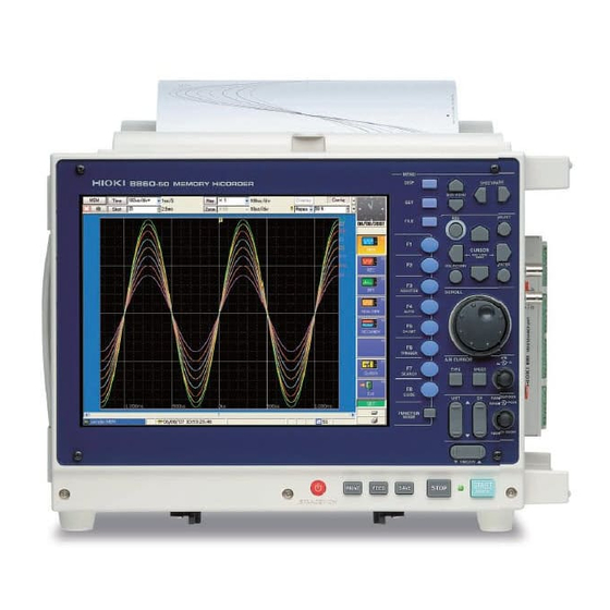
- Page 1 INPUT MODULE GUIDE 8860 8861 MEMORY HiCORDER This Guide describes the optional input mod- ules, related cable connection procedures, and their settings and specifications.
- Page 3 Notes for Installing the Input Units in Model 8861 IMPORTANT: When Model 8958 16ch SCANNER UNIT and 4 or more units of Model 8946 4ch ANALOG UNIT are installed in Model 8861 at the same time, only a maximum of 3 units of Model 8946 can be installed to the UNIT 1-4 slots of Model 8861.
- Page 4 Please refer to the following flow chart to when installing input units: Will model 8958 be installed? Will 4 or more units Model 8946 be installed? Up to 3 units of Model 8946 can be installed to the UNIT As much as possible, install As much as possible, install 1-4 slots.
-
Page 5: Table Of Contents
Contents Contents Introduction ..................1 Structure of this Document..............3 Chapter 1 Overview ___________________________________ 5 Product Overview ..............5 Input Module Usage List ............. 9 List of Input Modules, Cables, Probes and Clamp Combinations ..............11 Chapter 2 Connections _______________________________ 13 Installing Input Modules (Adding or Replacing) .... - Page 6 Contents 3.5.1 Measuring Frequency, 50/60 Hz and Rotation Rate ..... 50 3.5.2 Pulse Count Measurement ........... 52 3.5.3 Pulse Duty Measurement ............53 3.5.4 Voltage Measurement ............54 3.5.5 Current Measurement ............55 Model 8947 Charge Unit Settings ........56 3.6.1 Voltage Measurement ............
- Page 7 Contents Analog Input Section ............86 5.2.1 Model 8936 Analog Unit ............86 5.2.2 Model 8937 Voltage/Temp Unit ..........88 5.2.3 Model 8938 FFT Analog Unit ..........90 5.2.4 Model 8939 Strain Unit ............91 5.2.5 Model 8940 F/V Unit ..............92 5.2.6 Model 8946 4-Ch Analog Unit ..........94 5.2.7 Model 8947 Charge Unit ............95 5.2.8...
- Page 8 Contents...
-
Page 9: Introduction
Which input module and cables to use with the instrument depend on your mea- surement application. Refer to this as appropriate for your application. (⇒ p. 3) • In this document, the “instrument” means the Model 8860 or 8861 Memory HiCorder. - Page 10 Introduction Safety Symbols In the manual, the symbol indicates particularly important informa- tion that the user should read before using the instrument. symbol printed on the instrument indicates that the user should refer to a corresponding topic in the manual (marked with the symbol) before using the relevant function.
-
Page 11: Structure Of This Document
Structure of this Document Structure of this Document Preparation Reference Location About the overview of input mod- ⇒ "1.1 Product Overview" ( p. 5) ules and logic groups Overview of usage, connections ⇒ "1.2 Input Module Usage List" ( p. 9) Overview of Input and settings Modules and Logic... - Page 12 Structure of this Document Maximum Input Voltage* of input module and Maximum Rated Voltage to Ground* Model 8936 Analog Unit This Instrument Input Module Model 8938 FFT Analog Unit 400 VDC max 370 VAC/DC Model 8959 DC/RMS Unit 370 VAC/DC Model 8956 Analog Unit Input Module This Instrument...
-
Page 13: Overview
1.1 Product Overview Chapter 1 Overview 1.1 Product Overview This chapter provides an overview of the optional input modules and input cables that can be used with this instrument. Refer to "Appendix 6 Disposing of the Instrument" in the Instruction Manual for a full list of options for this instrument. - Page 14 1.1 Product Overview Input cables for voltage measurement with input modules (except the Model 8958 16-Ch Scanner Unit) 9197 Connection Cord 9198 Connection Cord 9217 Connection Cord For high voltage, maximum input volt- For low voltage, maximum input volt- Maximum input voltage: 300 V (for age: 500 V (large alligator clips) age: 300 V (small alligator clips) BNC output)
- Page 15 1.1 Product Overview Current Measurement Input Module Input modules for voltage measurement (except the Model 8958 16-Ch Scanner Unit) 8940 F/V Unit ⇒ Current can be measured using a clamp. Refer to "Voltage Measurement" ( p. 5) for in- 2 channels, 1 MS/s, 12-bit, clamp input put modules.
- Page 16 1.1 Product Overview Frequency, Rotation Rate, Commercial Line Frequency (50/60 Hz), Pulse Count, Acceleration Measurement Pulse Duty Measurement Input Module 8940 F/V Unit 8947 Charge Unit 2 channels, 1 MS/s, 12-bit 2 channels, 1 MS/s, 12-bit • Frequency: can be measured from the input pulse corresponding to •...
-
Page 17: Input Module Usage List
1.2 Input Module Usage List 1.2 Input Module Usage List Voltage Measurement Recommended Input Connection Setting To Perform This Measurement Use to connect Module Procedure Procedure Up to 2 channels per ⇒ ⇒ Model 8936 Analog Unit p. 17) ( p. - Page 18 1.2 Input Module Usage List Current Measurement To Perform This Recommended Connection Setting Use to connect Remarks Measurement Input Module Procedure Procedure Models 3273/ 3273-50 Clamp-On Probe To read current values di- A conversion cable is ⇒ Model 8940 F/V Models 9270 to 9272 p.
-
Page 19: List Of Input Modules, Cables, Probes And Clamp Combinations
1.3 List of Input Modules, Cables, Probes and Clamp Combinations 1.3 List of Input Modules, Cables, Probes and Clamp Combinations Δ − O = Compatible, = Incompatible, = Compatible, but scaling required Input Module Measurement Use to connect Parameter 8936 8937 8938 8939 8940 8946 8947 8956 8957 8958 8959 8960 −... - Page 20 1.3 List of Input Modules, Cables, Probes and Clamp Combinations...
-
Page 21: Chapter 2 Connections
Chapter 2 Connections This chapter describes the installation and connection of input modules to the instrument. Refer to the Quick Start Manual for other connections. Input modules for measurement (analog inputs) Install the input module(s) in the instrument’s input module compartment. ⇒... -
Page 22: Installing Input Modules (Adding Or Replacing)
2.1 Installing Input Modules (Adding or Replacing) 2.1 Installing Input Modules (Adding or Replacing) Input modules specified at the time the instrument is ordered are supplied prein- stalled. Use the following procedures to add or replace input modules, or to remove them from the instrument. - Page 23 2.1 Installing Input Modules (Adding or Replacing) Installing an input module Required item: One Phillips-head screwdriver Right Side Turn the instrument’s POWER switch Off. With attention to the orientation of the input module, insert it firmly all the way in. Make certain that the labels on the input module’s panel face the same direction as the labels on the right side of the instru- ment.
-
Page 24: Connecting The Cables
• Do not use cables other than those specified by Hioki. The specified cables include insulated BNC plugs to avoid electric shock. An uninsu- lated BNC plug may cause electric shock or damage to the BNC jack. -
Page 25: Connecting To An Analog Unit (Models 8936, 8938, 8946, 8956 And 8957)
2.2 Connecting the Cables 2.2.2 Connecting to an Analog Unit (Models 8936, 8938, 8946, 8956 and 8957) ⇒ Be sure to read "2.2.1 Connection Preparations" ( p. 16) before connecting. Input modules Any of the following connects to a BNC jack on an input •... -
Page 26: Connecting To The Model 8937 Voltage/Temp Unit
2.2 Connecting the Cables 2.2.3 Connecting to the Model 8937 Voltage/Temp Unit ⇒ For voltage measurement, be sure to read "2.2.1 Connection Preparations" ( p. 16) before connecting. Input module Voltage Measurement: Model 8937 Voltage/Temp Unit Any of the following connects to a BNC jack on an input module. - Page 27 2.2 Connecting the Cables Connection Procedure: Voltage Measurement Required item: Connection cord BNC jack Connecting the cable Connect the BNC plug on the cable to a BNC jack on the input module. BNC plug slots Align the slots in the BNC plug with the guide pins on the jack on the input module, then push and twist the plug clockwise until it locks.
-
Page 28: Connecting To A Strain Unit (Models 8939 And 8960)
2.2 Connecting the Cables 2.2.4 Connecting to a Strain Unit (Models 8939 and 8960) Input module Connect the strain gauge converter* to the input module jack. Model 8939 Strain Unit (conversion cable supplied) (Depending on the sensor, the supplied conversion cable may be needed.) Maximum Input Voltage (⇒... -
Page 29: Connecting To The Model 8940 F/V Unit
2.2 Connecting the Cables 2.2.5 Connecting to the Model 8940 F/V Unit ⇒ For voltage measurement, be sure to read "2.2.1 Connection Preparations" ( p. 16) before connecting. ⇒ For current measurement, read also "2.3 Connecting Clamps" ( p. 29). Input module Frequency, Pulse Totalization and Duty, and Voltage Model 8940 F/V Unit... - Page 30 2.2 Connecting the Cables To maintain safety, always use the optional Model 9318 or 9319 Conversion Cables when using one of theses clamp models: 3273, 3273-50, 9270 – 9272 or 9277 – 9279. Connection Procedure: Frequency, Pulse Totalization and Duty, and Voltage Measurement Required item: Connection Cables BNC jack...
- Page 31 2.2 Connecting the Cables Connection Procedure: Current measurement (with Model 9319 Conversion Cable) (for Model 3273 or 3273-50Clamp-On Probe) Example: When using the Model 3273 Clamp-On Probe Sensor Receptacle Required item: Models 9319 Conversion Cable and 3273 Clamp-On BNC jack Probe Align the slots in the clamp-on probe plug Connecting the clamp and the...
-
Page 32: Connecting To The Model 8947 Charge Unit
2.2 Connecting the Cables 2.2.6 Connecting to the Model 8947 Charge Unit Before measuring voltage and connecting to the BNC jack, be sure to read "2.2.1 Connec- ⇒ tion Preparations" ( p. 16). Input module Measurement using a piezoelectric acceleration sensor: Model 8947 Charge Unit Connect to the BNC jack or miniature receptacle (according to the particular sensor). - Page 33 2.2 Connecting the Cables Connection Procedure: Using a preamplified acceleration sensor Required item: BNC jack Preamplified acceleration sensor Connecting a preamplified Connect the BNC plug from the sensor to acceleration sensor a BNC jack on the input module. Align the slots in the BNC plug with the guide BNC plug slots pins on the jack on the input module, then push and twist the plug clockwise until it locks.
-
Page 34: Connecting To The Model 8958 16-Ch Scanner Unit
2.2 Connecting the Cables 2.2.7 Connecting to the Model 8958 16-Ch Scanner Unit Input module Connect to the terminal block on the input module. Model 8958 16-Ch Scanner Unit Temperature Measurement: Thermocouple Voltage Measurement: Input Cable Maximum Input Voltage (⇒ p. 4) Recommended cables: Solid 0.14 to 1.5 mm Stranded 0.14 to 1 mm 16 to 26 AWG... - Page 35 2.2 Connecting the Cables Scanner Unit Zero Position Adjustment The zero position of the Model 8958 16-Ch Scanner Unit needs to be adjusted in the following cases. If the adjustment is not performed, the accuracy specification may not be satisfied. Allow one hour warm-up after turning power on before adjusting.
-
Page 36: Connecting To The Model 8959 Dc/Rms Unit
2.2 Connecting the Cables 2.2.8 Connecting to the Model 8959 DC/RMS Unit ⇒ Be sure to read "2.2.1 Connection Preparations" ( p. 16) before connecting. Input module Any of the following connects to a BNC jack on an input Model 8959 DC/RMS Unit module. -
Page 37: Connecting Clamps
Use a clamp that provides voltage output for current measurement. Refer to "1.3 List of Input Modules, Cables, Probes and Clamp Combinations" (⇒ p. 11) for compatible combinations of Hioki clamps and input modules. Refer also to the clamp’s Instruction Manual for clamp-specific details. Preparations for Using Clamps Connect the clamp-on sensors to the instrument first, and then to the active lines to be measured. - Page 38 2.3 Connecting Clamps Connection Procedure Example: Connecting the Model 9018-10 Clamp-On Probe to the 8936 Analog Unit Required item: BNC jack 9018-10 Clamp-On Probe Connecting Clamps Connect the probe to a BNC jack on the input module. BNC plug slots Clamp the sensor around the measure- ment object.
-
Page 39: Connecting A Differential Probe
2.4 Connecting a Differential Probe 2.4 Connecting a Differential Probe Input modules that are compatible with the Model 9322 Differential Probe: • Model 8940 F/V Unit* • Voltage measurement input modules other than the Model 8940 * *1. The Model 9325 Power Cord or Model 9418-15 AC Adapter is required for connection. *2. - Page 40 2.4 Connecting a Differential Probe Connection Procedure: When connecting to the Model 8940 F/V Unit (using the 9325 Power Cord) BNC jack BNC plug slots Required item: Model 9322 Differential Probe and 9325 Power Cord Lock Sensor connector Input module Connect the power cord to the power jack connector guide pins on the probe.
- Page 41 2.4 Connecting a Differential Probe Connection Procedure: Measuring voltage with the input module (using the Model 9418-15 AC Adapter) Example: Connecting to the Model 8936 Analog Unit BNC jack Required item: BNC plug slots 9322 Differential Probe and 9418-15 AC Adapter Lock Connect the BNC plug on the probe to a BNC jack on the input module.
- Page 42 2.4 Connecting a Differential Probe Connection Procedure: Supplying power from the Model 9687 Probe Power Unit (Using the Model 9248 Power Cord) Example: Connecting to the Model 8936 Analog Unit Required item: BNC plug slots Model 9322 Differential Probe and Model 9248 Power Cord Lock BNC jack Connect the BNC plug on the probe to a...
-
Page 43: Connecting Attenuating Probes
2.5 Connecting Attenuating Probes 2.5 Connecting Attenuating Probes The Model 9665 10:1 Probe and 9666 100:1 Probe can be connected to the following input modules: • Model 8936 Analog Unit • Model 8938 FFT Analog Unit • Model 8956 Analog Unit •... - Page 44 2.5 Connecting Attenuating Probes Calibration Required item: External I/O Flat-blade screwdriver (2.6-mm blade) Terminals Connect the probe between the TRIG.OUT/CAL and GND To Insert external I/O terminals using metal pins or two short leads Metal pin example: Mac8 • DH-4-20 pin for surface mounting •...
-
Page 45: Connecting Logic Probes
• Model 9320-01 Logic Probe Refer to the instruction manual supplied with the logic probe for specific details. Do not connect logic probes other than those supplied by Hioki to the logic inputs. For users of the following legacy models:... - Page 46 2.6 Connecting Logic Probes • Maximum logic probe input voltages are as follows. Do not measure if the maximum voltage would be exceeded, as damage the instrument or personal injury may result. Model 9327 Logic Probe: +50 VDC Model 9320-01 Logic Probe: +50 VDC Model 9321-01 Logic Probe: 250 Vrms (HIGH range), 150 Vrms (LOW range) •...
- Page 47 2.6 Connecting Logic Probes Logic Probe Usage Procedures Using Model 9327 and 9320-01 Logic Probe Alligator clip lead When measuring digital signals IC clip leads (Digital input) Input selector Connect the IC clip leads to the logic probe. Set the input selector to DIGITAL. Connect the alligator clip to the circuit ground.
- Page 48 2.6 Connecting Logic Probes Using the Model 9321-01 Logic Probe Connect to the measurement Clips object Set the input selector in accordance with the measured voltage. LOW range: On/off for 100 VAC and 24 VDC, etc. HIGH range: On/off for 200 VAC, etc. Connect the clips to the measurement object.
-
Page 49: Supplying Power From The Model 9687 Probe Power Unit
To avoid damage, do not use the power supply for any purpose other than supplying power. There are limits to how many probes can be used with a single Model 8860 or 8861 with a 9687 installed. - Page 50 2.7 Supplying power from the Model 9687 Probe Power Unit...
-
Page 51: Input Channel Settings
Input Channel Chapter 3 Settings After turning power on, set the measurement criteria before measuring. This chapter describes the input channel setting procedures for each input mod- ule. Refer to "3.10 About Setting Contents" (⇒ p. 64) for details of each setting. Refer to the Instruction Manual for other settings. -
Page 52: Analog Unit Settings (Models 8936, 8946 And 8956)
3.1 Analog Unit Settings (Models 8936, 8946 and 8956) 3.1 Analog Unit Settings (Models 8936, 8946 and 8956) Set the input channel for voltage measurement when using the following input modules: • Model 8936 Analog Unit • Model 8956 Analog Unit •... -
Page 53: Model 8937 Voltage And Temperature Unit Settings
3.2 Model 8937 Voltage and Temperature Unit Settings 3.2 Model 8937 Voltage and Temperature Unit Settings 3.2.1 Voltage Measurement ([One Ch] Page of Channel Setting Screen) Execute to adjust input ⇒ signal offset. p. 76) Displayed when the measurement range is 500 µV to 2 mV. Setting Procedure Use the CURSOR... -
Page 54: Temperature Measurement
3.2 Model 8937 Voltage and Temperature Unit Settings 3.2.2 Temperature Measurement ([One Ch] Page of Channel Setting Screen) [Voltage] measurement mode is selected upon system reset. Setting Procedure Use the CURSOR keys to move among items. Select a setting with the keys. - Page 55 3.2 Model 8937 Voltage and Temperature Unit Settings • The upper and lower limits of measurement input depend on the measure- ment range. Refer to "About Measurement Range, Upper and Lower Input Limits and the Waveform Display:" (⇒ p. 64). •...
-
Page 56: Model 8938 Fft Analog Unit Settings
3.3 Model 8938 FFT Analog Unit Settings 3.3 Model 8938 FFT Analog Unit Settings ([One Ch] Page of Channel Setting Screen) Execute to adjust input signal offset. ⇒ p. 76) Setting Procedure Use the CURSOR keys to move among items. Select a setting with the keys. -
Page 57: Strain Unit Settings (Models 8939 And 8960)
3.4 Strain Unit Settings (Models 8939 and 8960) 3.4 Strain Unit Settings (Models 8939 and 8960) ([One Ch] Page of Channel Setting Screen) 8960 8939 Setting Procedure Use the CURSOR keys to move among items. Select a setting with the keys. -
Page 58: Model 8940 F/V Unit Settings
3.5 Model 8940 F/V Unit Settings 3.5 Model 8940 F/V Unit Settings Settings are related to the following measurements. One measurement type can be set per channel. • Measure frequency from the input pulse corresponding to the measurement waveform (⇒ p. 50) •... - Page 59 3.5 Model 8940 F/V Unit Settings Select according to the cable or probe being used [Probe] Select the probe attenuation ⇒ 75). [ 1:1, 10:1, 100:1, 1000:1(9322+9325) or 1000:1(9322+9418) ] ⇒ [Threshold] Set the threshold value ( p. 72). Set the threshold level [Pull-Up] Enable (set On) the pull-up resistance when connecting to an Set pull-up...
-
Page 60: Pulse Count Measurement
3.5 Model 8940 F/V Unit Settings 3.5.2 Pulse Count Measurement ([One Ch] Page of Channel Setting Screen) [Frequency] measurement mode is selected upon system reset. Setting Procedure Use the CURSOR keys to move among items. Select a setting with the keys. -
Page 61: Pulse Duty Measurement
3.5 Model 8940 F/V Unit Settings 3.5.3 Pulse Duty Measurement ([One Ch] Page of Channel Setting Screen) [Frequency] measurement mode is selected upon system reset. Setting Procedure Use the CURSOR keys to move among items. Select a setting with the keys. -
Page 62: Voltage Measurement
3.5 Model 8940 F/V Unit Settings 3.5.4 Voltage Measurement ([One Ch] Page of Channel Setting Screen) [Frequency] measurement mode is selected upon system reset. Execute to adjust input ⇒ signal offset. p. 76) Setting Procedure Use the CURSOR keys to move among items. Select a setting with the keys. -
Page 63: Current Measurement
3.5 Model 8940 F/V Unit Settings 3.5.5 Current Measurement When using the Model 9018-10 and 9132-10 Clamp-On Probe, select [Voltage] mode. ⇒ "3.5.4 Voltage Measurement" ( p. 54) ([One Ch] Page of Channel Setting Screen) [Frequency] measurement mode is selected upon system reset. Execute to adjust input ⇒... -
Page 64: Model 8947 Charge Unit Settings
3.6 Model 8947 Charge Unit Settings 3.6 Model 8947 Charge Unit Settings Make settings regarding input channels for measuring voltage or acceleration (Charge and Preamp). One type can be measured per channel. 3.6.1 Voltage Measurement ([One Ch] Page of Channel Setting Screen) [Charge] measurement mode is selected upon system reset. -
Page 65: Acceleration Measurement (Charge, Preamp)
3.6 Model 8947 Charge Unit Settings 3.6.2 Acceleration Measurement (Charge, Preamp) ([One Ch] Page of Channel Setting Screen) [Charge] measurement mode is selected upon system reset. Setting Procedure Use the CURSOR keys to move among items. Select a setting with the keys. - Page 66 3.6 Model 8947 Charge Unit Settings Supplement ___________________________________________________ Before connecting sensors and probes To avoid electric shock or damage to the measurement object, turn the instrument off before connecting a sensor or probe to the BNC jack. When the [Preamp] measurement mode is selected, internal power (15 V @ 2 mA) is applied to the BNC jack when measurement starts.
-
Page 67: Model 8957 High Resolution Unit Settings
3.7 Model 8957 High Resolution Unit Settings 3.7 Model 8957 High Resolution Unit Settings ([One Ch] Page of Channel Setting Screen) Execute to adjust input ⇒ signal offset. ( p. 76) Setting Procedure Use the CURSOR keys to move among items. Select a setting with the keys. -
Page 68: Model 8958 16-Ch Scanner Unit Settings
3.8 Model 8958 16-Ch Scanner Unit Settings 3.8 Model 8958 16-Ch Scanner Unit Settings Before Setting The zero position of the Model 8958 16-Ch Scanner Unit needs to be adjusted in the following cases. ⇒ "Scanner Unit Zero Position Adjustment" ( p. -
Page 69: Temperature Measurement
3.8 Model 8958 16-Ch Scanner Unit Settings 3.8.2 Temperature Measurement ([One Ch] Page of Channel Setting Screen) [Voltage] measurement mode is selected upon system reset. Setting Procedure Use the CURSOR keys to move among items. Select a setting with the keys. - Page 70 3.8 Model 8958 16-Ch Scanner Unit Settings • The upper and lower limits of measurement input depend on the measure- ment range. Refer to "About Measurement Range, Upper and Lower Input Limits and the Waveform Display:" (⇒ p. 64). • When the input terminals of the Model 8958 16-Ch Scanner Unit are subject to strong drafts: Loss of thermal equilibrium of the input section may result in measurement errors.
-
Page 71: Model 8959 Dc/Rms Unit Settings
3.9 Model 8959 DC/RMS Unit Settings 3.9 Model 8959 DC/RMS Unit Settings ([One Ch] Page of Channel Setting Screen) [DC] measurement mode is se- Example: Measuring RMS values lected upon system reset. Execute to adjust input ⇒ signal offset. p. 76) Setting Procedure Use the CURSOR... -
Page 72: About Setting Contents
3.10 About Setting Contents 3.10 About Setting Contents 3.10.1 Measurement Range Setting Select the appropriate measurement range. The setting value is the units per division on the vertical axis. Use the RANGE/POSN knob to make the setting independently from the cursor position. -
Page 73: Setting Input Coupling
3.10 About Setting Contents Example: Zero position = 50%, Magnification = ×1, Thermocouple = type T (using Model 8973) (Measurement input range of T = -200 to 400°C Upper limit of mea- Upper limit of T surement input range measurement input exceeded Thermocouple: T Measurement... -
Page 74: Low-Pass Filter (Lpf) Settings
3.10 About Setting Contents 3.10.3 Low-Pass Filter (LPF) Settings To suppress high-frequency components, select a low-pass filter within the input module Setting Item: [LPF] Selections Description The low-pass filter is disabled. (Default setting) Applies a filter with 5-Hz cutoff frequency. 500Hz Applies a filter with 500-Hz cutoff frequency. -
Page 75: Anti-Aliasing Filter (Aaf) Settings
3.10 About Setting Contents 3.10.4 Anti-Aliasing Filter (AAF) Settings Enable the anti-aliasing filter to remove aliasing distortion. The cutoff frequency is automatically set according to the time axis range setting. Setting Item: [AAF] Selections Description The anti-aliasing filter is disabled. (Default setting) The anti-aliasing filter is enabled. -
Page 76: Thermocouple (Sensor) Type Setting
3.10 About Setting Contents 3.10.6 Thermocouple (Sensor) Type Setting Set to match the type of thermocouple being used. Setting Item: [Sensor] 8937 Voltage/Temp Unit Measurement Measurement Selections Selections Range Range -200 to 1350°C 0 to 1700°C -200 to 1100°C 0 to 1700°C -200 to 800°C 300 to 1800°C -200 to 400°C... -
Page 77: Drift Correction Setting
3.10 About Setting Contents 3.10.8 Drift Correction Setting This function periodically corrects for drift of the reference potential (about once per second) to improve thermal characteristics in thermocouple mode. Setting Item: [Drift] Selections Description Drift correction is disabled. (Default setting) Drift correction is enabled. -
Page 78: Hold Setting
3.10 About Setting Contents 3.10.10 Hold Setting During measurement, the measured frequency value can be retained by the Hold function until the frequency of the next cycle has been determined. Also, if the value is not retained and the next value cannot be determined within a specified period, one half of the last measured value can be displayed. -
Page 79: Pull-Up Setting
3.10 About Setting Contents Example: Measuring frequency dropping to 0 Hz, and then increasing Actual Phenomena Frequency drops from a certain cycle to 0 Hz, and then increases from that point. Hold: On The previous value is retained until the 0-Hz event. [Hz] Hold: 10-ms Off At frequencies below 100 Hz, the displayed value is suc-... -
Page 80: Threshold Setting
3.10 About Setting Contents 3.10.12 Threshold Setting Sets threshold value. Measures when the waveform crosses a preset threshold. Setting Item: [Threshold] Selections Description ↑↑ Increases value by large steps. ↑ Increases value by small steps. ↓ Decreases value by small steps. ↓↓... -
Page 81: Sensor Sensitivity Setting
3.10 About Setting Contents 3.10.14 Sensor Sensitivity Setting Sets the value per m/s defined for the acceleration sensor to be used. Setting Item: [Sensitivity] Setting Range: 0.1 to 10 (pC/(m/s )) [Charge], 0.1 to 10 (mV/(m/s [Preamp] When using a sensor with specified value per G: ⇒... - Page 82 3.10 About Setting Contents To Use a Sensor Outside of the Setting Range The scaling function can be employed to use a sensor outside of the setting range. On the Channel Settings screen, select the channel on which to use the sensor outside of the setting range.
-
Page 83: Probe Attenuation Selection
3.10 About Setting Contents 3.10.15 Probe Attenuation Selection Probe attenuation can be selected when measuring using a connection cable, differential probe or attenuating probe. (Only for voltage measurement) By matching the input channel probe setting to the attenuation ratio of a probe connected to an analog input module, the voltage axis range is automatically converted for direct reading of numerical values. -
Page 84: Executing Zero Adjustment
3.10 About Setting Contents 3.10.17 Executing Zero Adjustment The input module can apply an internal offset to set the reference potential of the instrument to zero volts. Adjustment applies to the currently selected range. Before executing zero adjustment • Turn power on and wait 30 minutes to allow the internal temperature of the input module to stabilize. - Page 85 3.10 About Setting Contents Offset cancellation cannot be executed in the following cases: • When measuring other than voltage or current • When the input voltage is more than ±10 divisions from zero About input voltage during offset cancellation The maximum input voltage and maximum rated voltage to ground are unaffected by offset cancellation of an input voltage to zero volts.
-
Page 86: Executing Auto-Balance
3.10 About Setting Contents 3.10.19 Executing Auto-Balance Auto-balance sets the reference output level of a transducer to the specified zero position. It is applicable only to a strain module. Before executing auto-balance • Turn power on and wait 1 hour to allow the internal temperature of the input module to stabilize. -
Page 87: Logic Input Settings
4.1 Operation Overview Logic Input Chapter 4 Settings After turning power on, set the measurement criteria before measuring. This chapter describes the settings related to logic inputs. Refer to "7.3 Displaying Logic Waveforms" in the Instruction Manual for setting details. Measurement status and trigger settings are the same as for analog inputs. -
Page 88: Setting Procedure
4.2 Setting Procedure 4.2 Setting Procedure Display Settings Screen Press the key. The Settings screen appears. Function setting is not needed. Selecting channels to use (when displayed with the memory function) (Default setting: depends on the settings of the channels to be used) Status Settings Screen Press the SUB MENU... - Page 89 4.2 Setting Procedure Select the time axis range and recording length Status Setting Screen (with memory function) Press the SUB MENU keys to select the [Status] menu item. (When using the memory function) Press the SHEET/PAGE keys to select the [Basic] page.
- Page 90 4.2 Setting Procedure Set the trigger conditions (if applying a trigger) (Default setting: Logic trigger [Off]) Trigger Settings Screen Press the SUB MENU keys to select the [Trigger] menu item. Press the SHEET/PAGE keys to select the [Logic] page. [Logic] page of the Trigger Settings screen appears.
-
Page 91: Chapter 5 Specifications
5.1 Logic Input Section Chapter 5 Specifications Refer to "Safety Information" for the “Measurement Category (Overvoltage Category)” in the Quick Start Manual. 5.1 Logic Input Section 5.1.1 Model 9327 Logic Probe ° ° Temperature and humidity 23 ±5 C(73±9 F), 35 to 80% RH range for guaranteed accu- racy Period of guaranteed accu-... -
Page 92: Model 9321-01 Logic Probe
5.1 Logic Input Section 5.1.2 Model 9321-01 Logic Probe ° ° Temperature and humidity 23 ±5 C(73±9 F), 35 to 80% RH range for guaranteed accu- racy Period of guaranteed accu- 1 year racy The number of input chan- 4 channels (Isolated from chassis and between channels) nels Input voltage range HIGH... -
Page 93: Model 9320-01 Logic Probe
5.1 Logic Input Section 5.1.3 Model 9320-01 Logic Probe ° ° Temperature and humidity 23 ±5 C(73±9 F), 35 to 80% RH range for guaranteed accu- racy Period of guaranteed accu- 1 year racy The number of input chan- 4 channels (Common ground between chassis and between channels) nels Input type Digital input / Contact input... -
Page 94: Analog Input Section
5.2 Analog Input Section 5.2 Analog Input Section Input module specifications are described here. Measurement error caused by sig- Measurement Es 1 ----------------------- – nal source impedance Error • Errors occur when the signal source impedance is greater than the input impedance of the module. - Page 95 5.2 Analog Input Section Effect of conducted radio- ±40%f.s. at 3 V max. (100 mV/div with 1 V DC input) frequency electromagnetic field Dielectric strength 3.7 kVAC for 1 minute (between input module and chassis, and between input modules) Dimensions Approx.
-
Page 96: Model 8937 Voltage/Temp Unit
5.2 Analog Input Section 5.2.2 Model 8937 Voltage/Temp Unit General specifications ° ° Temperature and humidity 23 ±5 C(73±9 F), 35 to 80% RH (when zero adjustment is executed 1 hour after power range for guaranteed accu- racy Period of guaranteed accu- 1 year racy 80 dB min. - Page 97 5.2 Analog Input Section Temperature input ° Measurement ranges 10, 20, 50, 100 C/div ° ° Measurement input range K: -200 to 1350 E: -200 to 800 ° ° J: -200 to 1100 T: -200 to 400 ° N: -200 to 1300°C R: 0 to 1700 °...
-
Page 98: Model 8938 Fft Analog Unit
5.2 Analog Input Section 5.2.3 Model 8938 FFT Analog Unit ° ° Temperature and humidity 23 ±5 C(73±9 F), 35 to 80% RH (when zero adjustment is executed 30 minutes after range for guaranteed power on) accuracy Period of guaranteed 1 year accuracy The number of input chan-... -
Page 99: Model 8939 Strain Unit
5.2 Analog Input Section 5.2.4 Model 8939 Strain Unit Temperature and humidity 23 ±5°C (73±9°F), 35 to 80% RH (When executing auto-balancing one hour after power range for guaranteed accuracy Period of guaranteed 1 year accuracy The number of input 2 channels channels με... -
Page 100: Model 8940 F/V Unit
5.2 Analog Input Section 5.2.5 Model 8940 F/V Unit General Specifications Temperature and humidity 23 ±5°C(73±9°F), 35 to 80% RH (when zero adjustment is executed 30 minutes after range for guaranteed power on) accuracy Period of guaranteed 1 year accuracy A/D resolution 12 bits Vertical axis resolution... - Page 101 5.2 Analog Input Section Frequency, Count, Duty Measurement Specifications Frequency ranges 0.05, 0.1, 0.5, 1,5, 10, 50, 100, 500 Hz/div 1, 5 kHz/div 5, 10, 50, 100, 500 r/min/div Power source frequency ranges: 50 Hz(40 to 60 Hz), 60 Hz(50 to 70 Hz) Frequency accuracy ±0.2%f.s.
-
Page 102: Model 8946 4-Ch Analog Unit
5.2 Analog Input Section 5.2.6 Model 8946 4-Ch Analog Unit Temperature and humidity 23 ±5°C (73±9°F), 35 to 80% RH (when zero adjustment is executed 30 minutes after range for guaranteed power on) accuracy Period of guaranteed 1 year accuracy The number of input 4 channels channels... -
Page 103: Model 8947 Charge Unit
5.2 Analog Input Section 5.2.7 Model 8947 Charge Unit General Specifications ° ° Temperature and humidity 23 ±5 C(73±9 F), 35 to 80% RH (when zero adjustment is executed 1 hour after power range for guaranteed accuracy Period of guaranteed 1 year accuracy The number of input... - Page 104 5.2 Analog Input Section Charge Input ° Temperature characteristic ±0.2%f.s./ Frequency characteristic 1 Hz to 50 kHz −3 Low-pass filter OFF, 500±50%, 5k±50% (Hz) -3 dB Maximum input charge ±500 pC (with six high-sensitivity ranges selected) ±50,000 pC (with six low-sensitivity ranges selected) Input terminal Miniature connector (#10-32 UNF) Input for Sensor Preamp...
-
Page 105: Model 8956 Analog Unit
5.2 Analog Input Section 5.2.8 Model 8956 Analog Unit Temperature and humidity 23 ±5°C (73±9°F), 30 to 80% RH (when zero adjustment is executed 30 minutes after range for guaranteed power on) accuracy Period of guaranteed 1 year accuracy The number of input 2 channels channels Measurement ranges... -
Page 106: Model 8957 High Resolution Unit
5.2 Analog Input Section 5.2.9 Model 8957 High Resolution Unit Temperature and humidity 23 ±5°C (73±9°F), 30 to 80% RH (when zero adjustment is executed 30 minutes after range for guaranteed power on) accuracy Period of guaranteed 1 year accuracy The number of input 2 channels channels... -
Page 107: Model 8958 16-Ch Scanner Unit
5.2 Analog Input Section 5.2.10 Model 8958 16-Ch Scanner Unit Temperature and humidity 23 ±5°C (73±9°F), 30 to 80% RH (When executing zero-position adjustment one hour af- range for guaranteed ter power on) accuracy Period of guaranteed 1 year accuracy Guaranteed accuracy period 1 year The number of input 16 channels (Each channel can be set for voltage, or for a thermocouple) - Page 108 5.2 Analog Input Section Voltage input: 50 μVp-p max. (with digital filter OFF, in 5 mV/div range, with input shorted) Noise ° ° Temperature input: 0.5 Cp-p max. (with digital filter OFF, in 10 C/div range, measure- ment mode: K, with input shorted) Input resistance 1 MΩ±5% (With Disconnect (Burn-Out) Detection disabled during voltage and thermo- couple measurement)
-
Page 109: Model 8959 Dc/Rms Unit
5.2 Analog Input Section 5.2.11 Model 8959 DC/RMS Unit ° ° Temperature and humidity 23 ±5 C(73±9 F), 30 to 80% RH (when zero adjustment is executed 30 minutes after range for guaranteed power on) accuracy Period of guaranteed 1 year accuracy The number of input 2 channels... -
Page 110: Model 8960 Strain Unit
5.2 Analog Input Section 5.2.12 Model 8960 Strain Unit ° ° Temperature and humidity 23 ±5 C(73±9 F), 35 to 80% RH (When executing auto-balancing 30 minutes after power range for guaranteed accuracy Period of guaranteed 1 year accuracy Number of input channels 2 channels Input terminals R05-R5F by TAJIMI... -
Page 111: Index
Index Index Index Numerics Specifications ..........99 8959 DC/RMS Unit Connection ............. 28 8936 Analog Unit Settings ............63 Connection ............17 Specifications ..........101 Settings ............44 Specifications ..........86 8960 Strain Unit Connection ............. 20 8937 Voltage/Temp Unit Conversion cable ........... 20 Connection ............18 Settings... - Page 112 Index Index Sensor sensitivity ..........73 Outside of the setting range ......74 Scaling ............73 Digital Filter (Digital F) ........67 Digital input ............39 Disconnect (Burn-Out) detection ......69 Drift correction ............ 69 Thermocouple ............ 68 Threshold ............72 Trigger conditions ..........
- Page 113 HIOKI 8860/8861 MEMORY HiCORDER Input Module Guide Publication date: January 2007 Revised edition 5 Edited and published by HIOKI E.E. CORPORATION Technical Support Section All inquiries to International Sales and Marketing Department 81 Koizumi, Ueda, Nagano, 386-1192, Japan TEL: +81-268-28-0562 / FAX: +81-268-28-0568 E-mail: os-com@hioki.co.jp...
- Page 114 HEAD OFFICE 81 Koizumi, Ueda, Nagano 386-1192, Japan TEL +81-268-28-0562 / FAX +81-268-28-0568 E-mail: os-com@hioki.co.jp / URL http://www.hioki.co.jp/ HIOKI USA CORPORATION 6 Corporate Drive, Cranbury, NJ 08512, USA TEL +1-609-409-9109 / FAX +1-609-409-9108 8860A985-05 07-01H Printed on recycled paper...
Need help?
Do you have a question about the 8860 and is the answer not in the manual?
Questions and answers