Table of Contents
Advertisement
Quick Links
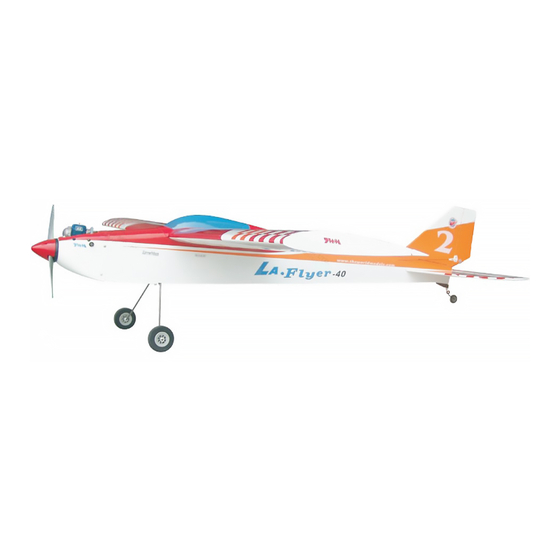
Requires : 4- channel
Wing Span
Wing Area
Flying Weight
Fuselage Length
Warning ! This model is not a toy.
It is designed for maximum performance. Please seek advice if one is not familiar with this kind
of engine powered precision model. Operating this model without prior preparation may cause
injuries. Remember, safety is the most important thing. Always keep this instruction manual
at hand for quick reference.
O. S . M A X - 46 L A Engine
Specifications
* Specifications are subject to change without notice.*
radio w/ standard
4
64 in / 1630 mm
657 sq in / 42.4 sq dm
5.1 lb / 2300 g
50 in / 1270 mm
ALMOST-READY-TO-FLY (ARF) SERIES
INSTRUCTION MANUAL
servos
FACTORY PRE-FABRICATED
MADE IN CHINA
Advertisement
Table of Contents

Related Manuals for The World Models Manufacturing LA FLYER-40


Summary of Contents for The World Models Manufacturing LA FLYER-40
- Page 1 INSTRUCTION MANUAL O. S . M A X - 46 L A Engine Requires : 4- channel radio w/ standard servos Specifications 64 in / 1630 mm Wing Span Wing Area 657 sq in / 42.4 sq dm Flying Weight 5.1 lb / 2300 g Fuselage Length 50 in / 1270 mm...
-
Page 2: Before You Begin
I N D E X BEFORE YOU BEGIN P. 1 PARTS LIST P. 2 ASSEMBLY P. 3 - 12 SAFETY PRECAUTIONS P. 12 BEFORE YOU BEGIN Read through the manual before you begin, so you will have an overall idea of what to do. Check all parts. -
Page 3: Parts List
Parts List 1. MAIN WING -- 1 pair 13. SCREW PM3x25mm -- 4 pcs WASHER d3xD7mm -- 8 pcs M3 NUT -- 8 pcs 2. WING JOINER 8x25x200mm -- 1 pc. 14. LINKAGE CONNECTOR Ø2.1mm -- 1 set 3. PLYWOOD 3x10x20mm -- 2 pcs RING Ø2.3mm -- 2 pcs 15. -
Page 4: Aileron Servo
Main Wing Pre-glued Please dry fit wing joiner into left and right wing to make sure they fit with the proper dihedral angle, mark the wing joiner if necessary. Apply epoxy glue to both sides of Main Wing all surfaces in contact. Use a stick to apply the glue to inner side of wing joiner sleeve, and apply the glue to wing joiner before putting them together. - Page 5 Aileron Servo Straper Fuel Tube Pushrod 1.8x100mm 6x5mm Fuel Tube 6 x 5mm Clevis Ring Bottom View Stabilizer & Elevator Screw Use thread locker when tightening PM3x16mm screw. Don't use excessive force as you are dealing with balsa. Washer d3xD7mm Washer PM3x16mm d3xD7mm...
-
Page 6: Fuel Tank
Vertical Fin / Rudder Completed P r e - g l u e d Engine Mount M3 x 20mm M3x20mm Socket Head Screw Washer d3xD7mm Engine Mount PL5111-030 Washer d3xD7mm Apply thread locker to screws. Blind nuts are off-centered to keep the spinner at the fuselage axis. -
Page 7: Main Landing Gear
Main Landing Gear Screw PA3 x 12mm Peel off shaded Portion covering film Collar 4.1mm Mounting Plate 4.1mm Collar 4.1mm Collar PA3 x12mm M3x3mm Set Screw Bottom View Tail Landing Gear Screw PA3x12mm Collar 2.1mm Screw PM2x12mm N u t M3 Set Screw 2.1mm Collar PA3x12mm... -
Page 8: Elevator Pushrod
Elevator Pushrod Screw PB2 x 12mm 1mm pilot holes for World Models tri-horn are pre-drilled. Ø Please look for pin-hole marks at under side of control surfaces. PB2x12mm Clevis Fuel Tube 6x5mm Ø Pushrod Ø1.8x720mm Pushrod Horn Ø1.8x720mm Bottom View Rudder Pushrod Screw PB2 x 12mm... - Page 9 Engine 100mm Screw PM3x25mm 3.93 in Washer d3xD7mm Installed Engine Position PM3x25mm Throttle Pushwire w/plastic tube 3mm Washer 3.2mm 3.2mm M3 Nut Washer Servo Set LINKAGE CONNECTOR Set Screw 3x3mm Linkage Connector Included with the radio Set. Washer M2 Nut Throttle Servo.
- Page 10 Servos Install and arrange the servo as shown in the diagram. Throttle Pushwire Switch Harness Elevator Servo Elevator Pushrod Ø1.2x400mm Front straper Fuel Tube Sponge Battery Rudder Pushrod Receiver Throttle Servo Rudder Servo Ø6x5mm Main Wing & Canopy Screw PM4x35mm Washer d4xD15mm PM4x35mm...
- Page 11 Wing Setting Adjust the wing and fuselage configuration as shown in the diagrams. A = A' B = B' C = C' P.10...
-
Page 12: Control Throws
Control Throws Adjust the control throws as shown in the diagram. These throws are good for general flying. You can adjust according Elevator to your personal preference. 15 mm 15 mm Rudder 20 mm 20 mm Aileron 6 mm 6 mm The ideal C.G. - Page 13 LINKAGE CONNECTOR HW7111050 & HW7111060 Drill 2mm hole at servo horn. Insert linkage connector into servo horn. Make sure shoulder of screw is cleared from servo horn. Add washer to reduce play if necessary. Shoulder Tighten up the round nut against the shoulder.
- Page 14 Usage of the transparent 3D template This transparent 3D template is used for position guidance of the actual cutting of the pre-painted cowling. Simply cut the transparent 3D template to fit your engine and exhaust pipe, then slide onto the actual cowling and use as template to mark the openings required for final cutting.
-
Page 15: Optional Parts
Optional Parts Fuel Filler 180mm Extension Code No. Size Package Code No. Size Package PL8110030 15 x 22 x 49mm 1 x 1 pc KW0011800 180mm 1 set 180mm Y-Cord Package Code No. Size KW0021800 180mm 1 pc Clevis Wrench Package Code No. - Page 16 The World Models Manufacturing Co., LTD. www .thew orldm odels .com A234PO18760810...
Need help?
Do you have a question about the LA FLYER-40 and is the answer not in the manual?
Questions and answers