Table of Contents
Advertisement
Quick Links
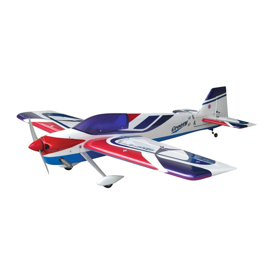
0.50-0.70 cu. in. displacement 4-stroke
Requires : 4 channels radio w/ 5 standard servos
Wing Span
Wing Area
Flying Weight
Fuselage Length
Warning ! This model is not a toy.
It is designed for maximum performance. Please seek advice if one is not familiar with this kind
of engine powered precision model. Operating this model without prior preparation may cause
injuries. Remember, safety is the most important thing. Always keep this instruction manual at
hand for quick reference.
-
Specifications
* Specifications are subject to change without notice.*
INSTRUCTION MANUAL
54.5 in / 1390 mm
648 sq in / 41.8 sq dm
5.7 lbs / 2600 g
53.5 in / 1360 mm
FACTORY PRE-FABRICATED
ALMOST-READY-TO-FLY (ARF) SERIES
MADE IN CHINA
Advertisement
Table of Contents

Subscribe to Our Youtube Channel
Related Manuals for The World Models Manufacturing GROOVY 3D 50


Summary of Contents for The World Models Manufacturing GROOVY 3D 50
- Page 1 INSTRUCTION MANUAL 0.50-0.70 cu. in. displacement 4-stroke Requires : 4 channels radio w/ 5 standard servos Specifications 54.5 in / 1390 mm Wing Span Wing Area 648 sq in / 41.8 sq dm Flying Weight 5.7 lbs / 2600 g Fuselage Length 53.5 in / 1360 mm * Specifications are subject to change without notice.*...
-
Page 2: Before You Begin
I N D E X BEFORE YOU BEGIN P. 1 PARTS LIST P. 2 ASSEMBLY P. 3 - 10 SAFETY PRECAUTIONS P. 10 BEFORE YOU BEGIN Read through the manual before you begin, so you will have an overall idea of what to do. Check all parts. -
Page 3: Parts List
Parts List 1. M N WING--1 pair WASHER d4xD9mm--4 pcs 2. CLEVIS--2 pcs 10. FUEL TANK 320cc--1 set STRAPER--2 pcs BALSA 8x8x91.5mm(For Fuel Tank Position Fixing)--1 pc. PLYWOOD 4x41x92.8mm(For Throttle Servo)--1 pc. FUEL TUBE Ø6x5mm--4 pcs TRI-HORN M3x14mm(s)--2 sets BALSA 6x6x41mm(For Throttle Servo Stand)--2 pcs SCREW PM2x25mm--6 pcs 11. -
Page 4: Aileron Servo
Main Wing Aileron Servo Lead A p p l y i n s t a n t t y p e C A g l u e t o b o t h s i d e s o f e a c h h i n g e . - Page 5 Main Wing Aileron Servo Lead A p p l y i n s t a n t t y p e C A g l u e t o b o t h s i d e s o f e a c h h i n g e .
-
Page 6: Tail Landing Gear
Vertical Fin & Rudder Apply instant type CA glue to both sides of each hinge. A = A' Tail Landing Gear Screw PA3 x 12mm PA3 x 12mm 1.5mm 2.1mm Collar Collar 2.1mm 3 x 3mm Set Screw 2.5mm Main Landing Gear Ø55mm Washer PM4x35mm Socket Head Screw... -
Page 7: Rudder Pullwire
Tri-horn Rudder Pullwire M3 x14mm Rigging Coupler Ø1.8x27mm Clevis Wire Ø1mm pilot holes for World Ø1.8x880mm Screw PM2x25mm Models tri-horn are pre-drilled. Please look for pin-hole marks at under side of control surfaces. Fuel Tube Ø6x5mm Copper Tube PM2x25mm M2 Nut Ø1mm pilot holes for World Models tri-horn are pre-drilled. - Page 8 Fuel Tank Fuel Tank Install Balsa 8 x 8 x 91.5mm (For Fuel Tank Position Fixing) Front Fuel Tank 320cc Fuel Tank 320cc Balsa 6x6x41mm Plywood 4x41x92. 8mm Bottom View Engine Installed Engine Position PM 3.5x30mm Screw M3.5 Nut d3.5xD8mm Washer M3.5 Nut d3.5 x D8mm Washer...
- Page 9 Step 1. Insert the aluminum wing tube with the pre-drilled hole end into the right wing. Align Main Wing the lines marked at the wing root and wing tube, then apply the PM3 x 18mm machine screw through the pre-drilled hole on top of the wing. ( please confirm the alignment of the hole by putting a 2.5mm diameter rod through the pre-drilled wing hole before applying the screw ) The hole on the wing tube is pre-threaded, do not over tighten the PM3 screw, the set up is for Screw...
- Page 10 Canopy Screw PWA2.3 x 8mm Apply double-sided tape d1.5 x D6.5 mm Silicon Grommet First insert the grommet to the canopy then apply screw. PWA2.3 x 8mm d1.5 x D6.5 mm Silicon Grommet Wing Setting Adjust the wing and fuselage configuration as shown in the diagrams. A = A ' B = B ' C = C '...
-
Page 11: Control Throws
Control Throws Adjust the control throws as shown in the diagram. These throws are good for general flying. You can adjust according to your personal preference. Elevator 35mm 35mm Rudder 50mm 50mm Ailerons 35mm 35mm The ideal C.G. position is 120mm (4.72 in.) behind C.G. - Page 12 LINKAGE CONNECTOR HW7111050 & HW7111060 Drill 2mm hole at servo horn. Insert linkage connector into servo horn. Make sure shoulder of screw is cleared from servo horn. Add washer to reduce play if necessary. Shoulder Tighten up the round nut against the shoulder.
-
Page 13: Optional Parts
Optional Parts Fuel Filler 180mm Extension Code No. Size Package Code No. Size Package PL8110030 15 x 22 x 49mm 1 x 1 pc KW0011800 180mm 1 set 180mm Y-Cord Package Code No. Size KW0021800 180mm 1 pc Clevis Wrench Package Code No. - Page 14 Usage of the transparent 3D template This transparent 3D template is used for position guidance of the actual cutting of the pre-painted cowling. Simply cut the transparent 3D template to fit your engine and exhaust pipe, then slide onto the actual cowling and use as template to mark the openings required for final cutting.
- Page 15 A2080805...
Need help?
Do you have a question about the GROOVY 3D 50 and is the answer not in the manual?
Questions and answers