Table of Contents
Advertisement
Quick Links
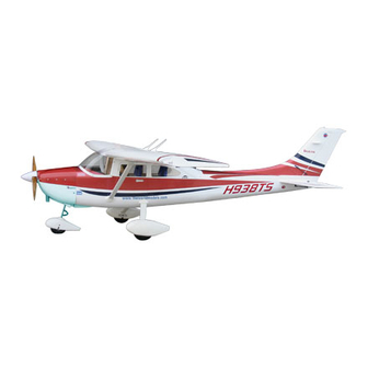
100 CC SK Y LINK
100 C C SKY LINK
100 C C SK Y LINK
100cc gasoline engine
Requires : 6-channel radio w/ 9 high torque servos
Wing Span
Wing Area
Flying Weight
Fuselage Length
Warning! This model is not a toy.
It is designed for maximum performance. Please seek advice if one is not familiar with this kind
of engine powered precision model. Operating this model without prior preparation may cause
injuries. Remember, safety is the most important thing. Always keep this instruction manual at
hand for quick reference.
A299PO24091006
*Specifications are subject to change without notice.*
The World Models
Manufacturing Co., Ltd.
www.theworldmodels.com
Specifications
144 in / 3650 mm
2731 sq in / 176.2 sq dm
36.5 Ib / 16.5 kg
112 in / 2850 mm
INSTRUCTION MANUAL
FACTORY PRE-FABRICATED
ALMOST-READY-TO-FLY(ARF)SERIES
MADE IN CHINA
Advertisement
Table of Contents

Related Manuals for The World Models Manufacturing 100 CC SKY LINK


Summary of Contents for The World Models Manufacturing 100 CC SKY LINK
- Page 1 INSTRUCTION MANUAL 100 CC SK Y LINK 100 C C SKY LINK 100 C C SK Y LINK 100cc gasoline engine Requires : 6-channel radio w/ 9 high torque servos Specifications Wing Span 144 in / 3650 mm Wing Area 2731 sq in / 176.2 sq dm Flying Weight 36.5 Ib / 16.5 kg...
-
Page 2: Before You Begin
100 C C S KY LINK 100 CC SKY LINK 100 C C SKY LINK INDEX BEFORE YOU BEGIN PARTS LIST ASSEMBLY P.3-P.13 SAFETY PRECAUTIONS P.13 BEFORE YOU BEGIN Read through the manual before you begin, so you will have an overall idea of what to do. -
Page 3: Parts List
Parts List 1. MAIN WING -- 1 pair SCREW HM3x12mm -- 4 pcs WASHER d5xD12mm -- 6 pcs 2. SOCKET HEAD SCREW M4x70mm -- 4 pcs COLLAR Ø5.1mm w/ set screw -- 4 sets SCREW PWA2.3x8mm -- 24 pcs M8 NYLON INSERT LOCK NUT -- 2 pcs M4 NYLON INSERT LOCK NUT -- 4 pcs WHEEL PANTS -- 1 pair PUSHROD M3x90mm w/ Threads(For Aileron) -- 2 pcs... - Page 4 Main Wing Aileron Servo Lead Pre-glued Bottom View Aileron & Flap Servos M4x70mm Socket Head Screw Lamp Cover M2x8mm Socket Head Screw PL4120300 Signal Lamp PWA2.3x8mm PWA2.3x8mm Screw Nylon Insert Lock Nut 1.5mm M2 Nut M2 Nylon Insert Lock Nut Heavy Duty Clevis Signal Lamp Wire Lead...
- Page 5 Elevator Servos M4x60mm Socket Head Screw PWA2.3x8mm Screw Nylon Insert Lock Nut Pre-glued Bottom view Heavy Duty Horn Bracket M2x8mm M4 Nylon M2 Nylon Insert Socket Head Screw PL4120300 Insert Lock Lock Nut M2 Nylon Insert Lock Nut Heavy Duty Heavy Duty Clevis Clevis Pushrod...
-
Page 6: Rudder Pushrod
Vertical Fin & Rudder Signal Lamp Signal Lamp Wire Lead Vertical Fin`s Wing 105x85x6mm Pre-glued Rudder Pushrod M2x8mm Socket Head Screw PL4120300 M4x50mm Socket Head Screw A’ PWA2.3x8 mm Screw Nylon Insert Lock Nut A=A’ 1.5mm M2 Nut M2 Nylon Insert Lock Nut PWA2.3 x 8mm Rudder Pushrod... - Page 7 Front Landing Gear Wheel Pant M4 x 6mm M5x70mm M4 x 6mm Socket Head Screw M4x6mm Socket Head Screw HM4x20mm Screw d5 x D12mm Washer HM3x12mm Screw d5 x D12mm M5 Nylon Washer Insert Lock M5 x 70mm HA3x18mm Screw M3 x 3mm Set Screw HA3x30mm...
-
Page 8: Main Landing Gear
Main Landing Gear Ø 5xM8x100mm Axle Shaft Set Screw Ø 5xM8x100mm M5x25mm Socket Head Screw Axle Shaft Nylon Insert Lock Nut HM3x12mm Screw Landing Gear Faring d5 x D12 mm Washer d5xD12mm Washer M5 x 25 mm Plate M8 Nylon Insert Lock Nut Collar 5.1mm Collar 5.1mm 5.1mm... -
Page 9: Fuel Tank
Fuel Tank Cable Tie Double-sided Tape Instrument Panel 1.5x8x500mm 40x160mm Fuel Tank 1500cc Completed Servo Set 3x3mm Set Screw 3x3mm Set Screw Throttle Pushwire Linkage Connector Washer M2 Nut Washer 1.5mm Throttle Servo. 2mm Washer M2 Nut Please refer to the attached sheet for linkage connector installation. Radio Equipment Install and arrange the servos as shown in the diagram. - Page 10 Canopy First insert the grommet to the canopy then apply screw. PWA2.3x12mm Screw PWA2.3x12mm PWA2.3x12mm PWA2.3x12mm d1.5xD6.5mm Silicon Grommet d1.5xD6.5mm Silicon Grommet Pilot Pilot Statues Completed Cowling First insert the grommet to the cowling then apply screw. Please refer to the attached sheet for usage of the transparent 3D template. Quick Release Nylon Rivet PA3x12mm Screw...
- Page 11 Main Wing Step 1. Insert the aluminum wing tube with the pre-drilled hole end into the right wing. Align the lines marked at the wing root and wing tube and apply the HM3 x 45mm & HM3x35mm machine screw through the pre-drilled hole on top of the wing. ( please confirm the alignment of the hole by putting a 2.5mm diameter rod through the pre-drilled wing hole before applying the screw ) HM3x45mm Screw...
- Page 12 Antenna & Ornament PA2x12mm Screw PA2x12mm 20mm Plywood inside 182mm Ornament Ornament Aileron Ornament Completed Elevator A299PO24091006 P.11...
-
Page 13: Control Throws
Decals Control Throws Adjust the control throws as shown in the diagram. These throws are good for general flying. You can adjust according to your personal preference. Rudder 45mm 45mm Elevator 40mm 40mm Flaps (near fuselage) 75mm Ailerons (away from fuselage) 30mm 30mm A299PO24091006... - Page 14 C.G. The ideal C.G. position is 153mm (6 in.) behind the leading edge measured at where the wing meets the fuselage. In order to obtain the C.G. specified, add weight to the fuselage or move the battery position. Check the C.G. before flying.
- Page 15 LINKAGE CONNECTOR HW7111050 & HW7111060 Drill 2mm hole at servo horn. Insert linkage connector into servo horn. Make sure shoulder of screw is cleared from servo horn. Add washer to reduce play if necessary. Shoulder Tighten up the round nut against the shoulder.
- Page 16 Product Registration Form (US Customers) We would like to share with you any relevant information regarding your model, including product news and free upgrade parts when applicable. Please fill in the following and send to AirBorne Models, 4749-K,Bennett Drive, Livermore, CA 94551 USA. 1.
- Page 17 Usage of the transparent 3D template This transparent 3D template is used for position guidance of the actual cutting of the pre-painted cowling. Simply cut the transparent 3D template to fit your engine and exhaust pipe, then slide onto the actual cowling and use as template to mark the openings required for final cutting.
-
Page 18: Optional Parts
Optional Parts ACCESSORIES) Clevis Wrench 180mm Extension Code No. Size Package Code No. Size Package PL8210010 KW0011800 1 set 180mm 1 set Small Clevis Large Clevis Special tool for clevis installation. Suitable for standard and small 180mm Y-Cord (EP) clevis. Code No. - Page 19 The World Models Manufacturing Co., Ltd. www.theworldmodels.com A299PO24091006...
Need help?
Do you have a question about the 100 CC SKY LINK and is the answer not in the manual?
Questions and answers