
Related Manuals for Hobby-Lobby Apache Princess


Summary of Contents for Hobby-Lobby Apache Princess
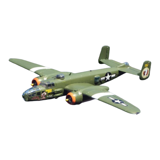
- Page 2 Hobby-Lobby is pleased to announce the eRC B-25 Mitchell “Apache Princess”, the first RC model airplane in its class to include scale action retractable landing gear with sequenced gear doors, counter rotating propellers, and working position lights. A great deal of the assembly is pre-done for you. This is a receiver ready airplane that only requires some simple assembly and the installation of your radio equipment and batteries to be ready to fly.
- Page 3 Before starting, use the contents list to take an inventory and make sure it is complete. If any parts are missing or are not of acceptable quality, contact Hobby-Lobby.com support at 1-866-WE-FLY-RC (1-866-933-5972) Contents List ¨ Fuselage ¨ Canopy Battery Hatch ¨...
- Page 4 1. This manual will help you assemble your B-25 Mitchell. Let’s start with the installation of the brushless motors. Plug the three motor wires into the three ESC wires. Do not worry about the plug-in order; we will check motor rotation in a later step.
- Page 5 5. Locate the various Y-connectors. See photo for identification. The triple connector is for the retracts (Ch. 5). The Y that does not have the signal wire is for the lights. 6. Photo shows the root end of a wing panel and identifies the various connectors.
- Page 6 9. Locate the fuselage and apply a bead of glue to the inside of the main wing opening. 10. Apply glue to the root end of one main wing panel. 11. Feed wires into the fuselage at front of the wing opening and insert the wing into the fuselage.
- Page 7 13. Again, make sure that the wing is fully seated in the opening as shown in the photo. 14. Locate the foam rectangle that creates the wire cover for the bottom of the wing. Apply a bead of glue around the edge. 15.
- Page 8 17. Insert the rudder pushrod Z-bend into the outermost hole on the inboard bell crank as shown in the photo. Repeat for the opposite side of the stabilizer. 18. Place the stabilizer in position on the fuselage and screw into position with the long screws as shown.
- Page 9 21. Install the two vertical fins on the horizontal stabilizer. A small amount of glue can be used if desired. 22. Screw fin into position as shown. 23. Install the short rudder pushrods to the outer bell cranks as shown in the photo. 24.
- Page 10 25. Temporarily install props on the motors. PLEASE NOTE: Both left and right hand props are provided in the kit. We recommend that the B-25 prop rotation be setup with the tips of the props rotating toward the wingtips at the top of their rotation. This means that from the pilots seat the right engine is rotating clockwise and the left engine counter clockwise.
- Page 11 30. Screw plastic prop hub to the shaft of the motor as shown. 31. Locate the injection molded detail parts. Glue the cockpit air intakes in place with a small amount of glue. 32. The fin aerial is installed on the top of the fuselage behind the ball turret.
- Page 12 34. Make pilot holes for the gun barrels with a thin Phillips screwdriver or length of music wire. Install gun barrels as shown. 35. Make pilot hole for side gun blister barrel and install as shown. 36. Install two gun barrels in tail position. 37.
- Page 13 38. Install barrels in turret. 39. Apply a thin bead of glue to the edge of the nose greenhouse and install on fuselage. Use the artwork as a guide to orientation. 40. With model on its back, mark a point that is 2-1/2”...
- Page 14 42. Install the power Y-conn to each ESC making sure that you plug the red-to-red and black-to-black. Feed the Deans plug into the cockpit area of the fuselage. 43. The flight battery is located under the cockpit. Lift from the rear to remove. A 3-cell Lipo battery of approx.
- Page 15 46. When the landing gear is retracted any wires should not obstruct the wheel. 47. When the gear is in the down position it should lock so that it does not collapse under load. 48. With the model upside down and your transmitter turned ON with the throttle in the OFF position;...
- Page 16 50. The landing gear retracts at a scale like speed. 51. Once the gear is completely retracted the gear doors are commanded to close. 52. Each gear door closes at a scale like speed 53. Once completely closed they are ready to reverse the operation for landing.
- Page 17 Recommended Control Throws Ailerons Low Rate 5/16" Up and Down High Rate 1/2" Up and Down Elevator Low Rate 5/16" Up and Down High Rate 1/2" Up and Down Rudder 1/4" Both Directions Center of Gravity 2-1/8"- 2-1/2" Back from the wing leading edge at the root Preflight If you are new to flying R/C aircraft, or a seasoned modeler, we recommend you have a fellow R/C modeler help you with the first flight.
-
Page 18: Radio Control
GENERAL 1. A model aircraft shall be defined as a non-human-carrying device capable of sustained flight in the atmosphere. It shall not exceed limitations established in this code and is intended to be used exclusively for recreational or competition activity. 2. - Page 19 Warranty Hobby-Lobby guarantees this kit to be free from defects in both material and workmanship at the date of purchase. This warranty does not cover any component parts damaged by use or modification. In no event shall Hobby-Lobby’s liability exceed the original cost of the purchased kit.
Need help?
Do you have a question about the Apache Princess and is the answer not in the manual?
Questions and answers