
Related Manuals for Hobby-Lobby Funster V2


Summary of Contents for Hobby-Lobby Funster V2
-
Page 1: Instruction Manual
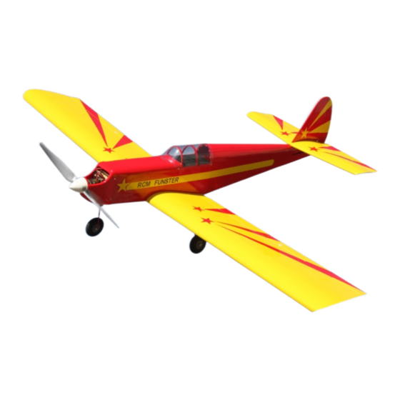
Instruction Manual Funster V2 ARF Wingspan: 72-1/2 in. Length: 53 in. Wing Area: 846 sq. in. Weight (with battery): 83 oz. - Page 2 Before starting, use the Contents List to take an inventory and make sure it is complete. If any parts are missing or are not of acceptable quality, contact Hobby-Lobby.com Support at 866-512-1444. This manual assumes the builder possess intermediate assembly skills. Seek help from...
- Page 3 1. After unpacking all parts, sort the hardware and place like parts into separate holders. This will speed the building process and give you a good visual of all the hardware provided. 2. Begin by hinging the ailerons to the main wing panels using the CA hinges.
- Page 4 7. Slide the servo wires through the wing and install the hatch using 4 of the smallest wood screws per hatch. 8. Install the nylon control horns to the ailerons. The nylon control horn positions are marked on the surfaces with pre- drilled pilot holes.
- Page 5 11. Find the two plastic arms and screw them onto the threaded flap control rod. You may have to drill out the plastic arm for an easier fit. Next, install the “Y” shaped pushrod linkage onto the servo and connect to the flap control arm as shown. You will connect the other side when joining the wings.
- Page 6 15. Install the wheels using a wheel collar on both sides of the wheels. 16. Locate the plastic nose gear mount, and the plastic pushrod with the wire in it. Install the pushrod through the slot shown making sure the side with the Z-Bend is facing forward.
- Page 7 19. Install the nose wheel as you did with the main wheels using a wheel collar on both sides of the wheel. 20. For the next steps we will first need to install the wing. Place the wing onto the fuselage and use the large nylon wing bolts to secure the wing to the fuselage.
- Page 8 23. Place the stabilizer onto the fuselage and make the area where it touches the fuselage. Your stabilizer should look like the photo now. 24. Find the 2 balsa triangle pieces and lay them down on the outside of the lines you just marked with the back edge of the pieces at the hinge line as shown.
- Page 9 27. Apply 30-minute epoxy to the fuselage area where the stabilizer will mount. Place the stabilizer onto the fuselage and make sure it is centered. Wipe up any access glue with a paper towel and rubbing alcohol. 28. Sight down the fuselage and make sure the horizontal stabilizer is parallel to the wing.
- Page 10 31. Install the rudder and elevator nylon control horns as shown. 32. Glue the balsa triangle pieces in place using epoxy or thin CA glue. 33. Find the two long carbon fiber pushrods. Inset them into the holes at the back of the fuselage, one on each side.
- Page 11 35. Install the rudder and elevator servos in the fuselage with the output arms facing the rear as shown. 36. The rudder servo will need a double- sided control arm as shown. Install the included EZ-Connector onto one side. 37. Center your servos and install the control arms and linkages as shown.
- Page 12 39. The receiver can be mounted using Velcro or double-sided tape. You can use 6” extensions for the aileron and flap channels to make it easier to install the wing. 40. The motor mount and fuselage firewall both have centering marks on them. Hold the mount up to the fuselage and align the marks to center the motor mount.
- Page 13 43. Connect your ESC to the motor and install on the side of the motor mount with Velcro. Use zip ties to secure the motor wires so they will not interfere with the motors operation. The power leads for the ESC should be placed inside the hole shown for access to the battery.
- Page 14 47. Use a 1/16” drill bit to make a pilot hole through the cowling and fuselage to create 4 mounting points, two on each side. 48. Use 4 of the smallest wood screws to secure the cowling. 49. Install your prop, washer and nut. 50.
- Page 15 51. Install the magnetic hatch by putting the back end in first and then laying the front down. Remove the hatch by first lifting the front and pulling up and away. 52. Congratulations, you’ve finished the assembly. Follow the information listed below for recommended control throws and center of gravity.
- Page 16 Warranty Hobby-Lobby guarantees this kit to be free from defects in both material and workmanship at the date of purchase. This warranty does not cover any component parts damaged by use or modification. In no event shall Hobby-Lobby’s liability exceed the original cost of the purchased kit.
- Page 17 Hobby Lobby International, Inc. 5614 Franklin Pike Circle Brentwood, TN 37027 (1-866-512-1444) www.hobby-lobby.com © 2010-2012 Hobby Lobby International, Inc. 5614 Franklin Pike Circle Brentwood, TN 37027 USA www.hobby-lobby.com...
Need help?
Do you have a question about the Funster V2 and is the answer not in the manual?
Questions and answers