Table of Contents
Advertisement
Quick Links
Advertisement
Chapters
Table of Contents
Troubleshooting

Related Manuals for Suzuki DR 125


Summary of Contents for Suzuki DR 125
- Page 1 DR-Z125/L 9 9 5 0 0 - 4 1 1 2 5 - 0 1 E...
-
Page 2: Table Of Contents
FOREWORD GROUP INDEX This manual contains an introductory description on the SUZUKI DR-Z125/L and procedures for its inspection/service and overhaul of its main compo- GENERAL INFORMATION nents. Other information considered as generally known is not included. PERIODIC MAINTENANCE Read the GENERAL INFORMATION section to familiarize yourself with the motorcycle and its main- tenance. -
Page 3: How To Use This Manual
HOW TO USE THIS MANUAL TO LOCATE WHAT YOU ARE LOOKING FOR: 1. The text of this manual is divided into sections. 2. The section titles are listed in the GROUP INDEX. 3. Holding the manual as shown at the right will allow you to find the first page of the section easily. - Page 4 Apply molybdenum oil solution. (mixture of engine oil and SUZUKl Measure in resistance range. MOLY PASTE in a ratio of 1 : 1) Apply SUZUKI SUPER GREASE “A”. Measure in current range. 99000-25030 (For USA) 99000-25010 (For the other counties) Apply SUZUKI SILICONE GREASE.
- Page 5 GENERAL INFORMATION GENERAL INFORMATION CONTENTS WARNING/CAUTION/NOTE .............. 1- 2 GENERAL PRECAUTIONS ..............1- 2 SUZUKI DR-Z125/LK3 (’03-MODEL) ..........1- 4 SERIAL NUMBER LOCATION ............1- 4 FUEL AND OIL RECOMMENDATION ..........1- 4 FUEL .................... 1- 4 ENGINE OIL ................. 1- 5 BRAKE FLUID ................1- 5...
-
Page 6: Warning/Caution/Note
GENERAL INFORMATION WARNING/CAUTION/NOTE Please read this manual and follow its instructions carefully. To emphasize special information, the symbol and the words WARNING, CAUTION and NOTE have special meanings. Pay special attention to the mes- sages highlighted by these signal words. Indicates a potential hazard that could result in death or injury. - Page 7 GENERAL INFORMATION " * If parts replacement is necessary, replace the parts with SUZUKI Genuine Parts or their equiv- alent. * When removing parts that are to be reused, keep them arranged in an orderly manner so that they may be reinstalled in the proper order and orientation.
-
Page 8: Suzuki Dr-Z125/Lk3 ('03-Model)
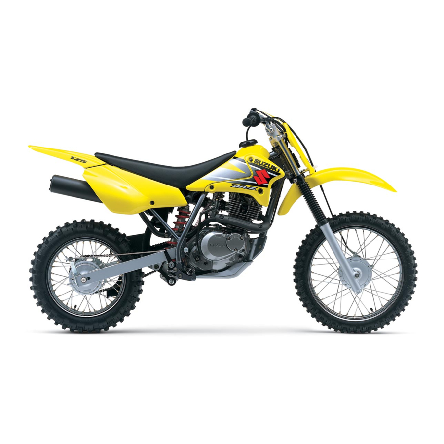
GENERAL INFORMATION SUZUKI DR-Z125/LK3 (’03-MODEL) LEFT SIDE RIGHT SIDE SERIAL NUMBER LOCATION The frame serial number or V.I.N. (Vehicle Identification Number) 1 is stamped on the right side of the steering head pipe. The engine serial number 2 is located on the left side of the crankcase. These numbers are required especially for registering the machine and ordering spare parts. -
Page 9: Engine Oil
Never re-use brake fluid left over from a previous servicing, which has been stored for a long period. FRONT FORK OIL SUZUKI fork oil SS-08 or an equivalent fork oil. BREAK-lN PROCEDURES During manufacture only the best possible materials are used and all machined parts are finished to a very high standard but it is still necessary to allow the moving parts to “BREAK-IN”... -
Page 10: Information Labels
GENERAL INFORMATION INFORMATION LABELS DR-Z125/L APPLIED SPECIFICATION LABEL or PLATE NAME E-28 E-03 ¡ Noise label — ¡ Information label — ¡ Fuel caution label — " ¡ Manual notice label — ¡ ¡ Warning safety label ¡ Certification plate —... -
Page 11: Specifications
GENERAL INFORMATION SPECIFICATIONS DIMENSIONS AND DRY MASS Overall length ............1 835 mm (72.2 in) 1 885 mm (74.2 in) ..DR-Z125L Overall width ............770 mm (30.3 in) Overall height ............1 060 mm (41.7 in) 1 095 mm (43.1 in)..DR-Z125L Wheelbase ............ -
Page 12: Chassis
GENERAL INFORMATION CHASSIS Front suspension ..........Telescopic, coil spring, oil damped, Rear suspension ..........Link type, coil spring, oil damped, Front suspension stroke........180 mm (7.1in) Rear wheel travel ..........160 mm (6.3in) 170 mm (6.7in) ....DR-Z125L Caster ..............28° 27° 30’ ......DR-Z125L Trail ..............88 mm (3.46 in) 99 mm (3.90 in) .....DR-Z125L Steering angle............45°... -
Page 13: Country And Area Codes
GENERAL INFORMATION COUNTRY AND AREA CODES The following codes stand for the applicable countries and areas. CODE COUNTRY OR AREA E-03 E-28 Canada... - Page 14 PERIODIC MAINTENANCE PERIODIC MAINTENANCE CONTENTS PERIODIC MAINTENANCE SCHEDULE ..........2- 2 PERIODIC MAINTENANCE CHART ...........2- 2 LUBRICATION POINTS ...............2- 3 MAINTENANCE AND TUNE-UP PROCEDURES .......2- 4 AIR CLEANER ................2- 4 VALVE CLEARANCE ..............2- 5 CAM CHAIN TENSION ADJUSTER ..........2- 6 SPARK PLUG ................2- 7 THROTTLE CABLE PLAY ............2- 8 ENGINE IDLE SPEED ..............2- 8 FUEL HOSE .................2- 9...
-
Page 15: Periodic Maintenance Schedule
PERIODIC MAINTENANCE PERIODIC MAINTENANCE SCHEDULE The chart below lists the recommended intervals for all the required periodic service work necessary to keep the motorcycle operating at peak performance and economy. NOTE: More frequent servicing may be performed on motorcycles that are use under severe conditions. PERIODIC MAINTENANCE CHART Interval Initially... -
Page 16: Lubrication Points
PERIODIC MAINTENANCE LUBRICATION POINTS Proper lubrication is important for smooth operation and long life of each working part of the motorcycle. Major lubrication points are indicated below. Clutch lever holder Side-stand pivot and spring hook Drive chain Throttle cable Front brake lever holder Brake pedal pivot NOTE:... -
Page 17: Maintenance And Tune-Up Procedures
PERIODIC MAINTENANCE MAINTENANCE AND TUNE-UP PROCEDURES This section describes the servicing procedures for each item in the Periodic Maintenance chart. AIR CLEANER Clean every 6 months. If the air cleaner is clogged with dust, intake resistance will be increase, resulting in a decrease in engine output and an increase in fuel consumption. -
Page 18: Valve Clearance
PERIODIC MAINTENANCE • Remove the drain plug 1 to allow any water to drain out. • Reinstall the cleaned air cleaner element in the reverse order of removal. Be sure to position the element snugly and correctly, so that no incoming air will by-pass it. Remember, the rapid wear of piston rings and the cylinder bore is often caused by a defective or poorly fitted element. -
Page 19: Cam Chain Tension Adjuster
PERIODIC MAINTENANCE NOTE: * The piston must be at (TDC) on the compression stroke in order to check the valve clearance or to adjust valve clear- ance. * The clearance specification is for COLD state. * To turn the crankshaft for clearance checking, rotate in the nor- mal running direction. -
Page 20: Spark Plug
PERIODIC MAINTENANCE NOTE: If the cam chain is noisy after having been adjusted, the push rod is probably sticking. Remove the cam chain tension adjuster, clean and lubricate the push rod to obtain smooth movement and proper tensioning action. SPARK PLUG Inspect every 6 months. -
Page 21: Throttle Cable Play
PERIODIC MAINTENANCE " Before using a spark plug wrench, carefully turn the spark plug by finger into the threads of the cylinder head to prevent damage. • Tighten the spark plug to the using the special tool. 0.6 – 0.8 mm # 09930-10121: Spark plug wrench set (0.024 –... -
Page 22: Fuel Hose
PERIODIC MAINTENANCE • Connect the electric tachometer or the multi circuit tester to the high-tension cord. • Start the engine and set the engine idle speed between 1 600 and 1 800 r/min by turning the throttle stop screw 1. $ Engine idle speed: 1 700 ±... -
Page 23: Engine Oil And Oil Filter
2-10 PERIODIC MAINTENANCE ENGINE OIL AND OIL FILTER ENGINE OIL REPLACEMENT Replace initially at 1 month and every 6 months there- after. • Place an oil pan below the engine. Drain oil by removing the engine oil drain plug 1 1 1 1 . •... -
Page 24: Spark Arrester
PERIODIC MAINTENANCE 2-11 OIL FILTER REPLACEMENT Replace initially at 1 month and every 12 months thereafter. • Drain the engine oil as described in the engine oil replace- ment procedure. • Remove the oil filter cap 1 and oil filter 2. •... -
Page 25: Drive Chain
* Rusted links * Kinked or binding links If any defects are found, the drive chain must be replaced. " The standard drive chain is DID428HG. SUZUKI rec- ommends to use this standard drive chain as a replacement. CHECKING AND ADJUSTING •... - Page 26 PERIODIC MAINTENANCE 2-13 • Place the motorcycle on the side-stand. • Loosen or tighten both chain adjusters 1 until the chain has 35 – 40 mm (1.4 – 1.6 in) of slack at the middle of the chain between the engine and rear sprockets as shown. The refer- ence marks 2 must be at the same position on the scale to ensure that the front and rear wheels are correctly aligned.
-
Page 27: Front Brake Lever Play (Dr-Z125)
2-14 PERIODIC MAINTENANCE FRONT BRAKE LEVER PLAY (DR-Z125) • Turn the adjusting nuts 1 so that the brake lever play A is within specification. $ Front brake lever play A A A A : 15 – 25 mm (0.6 – 1.0 in) FRONT DISC BRAKE (DR-Z125L) BRAKE PADS The extent of brake pad wear can be checked by observing the... - Page 28 PERIODIC MAINTENANCE 2-15 AIR BLEEDING THE BRAKE FLUID CIRCUIT Air trapped in the brake fluid circuit acts like a cushion to absorb a large proportion of the pressure developed by the master cyl- inder and thus interferes with the full braking performance of the brake caliper.
-
Page 29: Rear Brake Pedal Height
2-16 PERIODIC MAINTENANCE FRONT BRAKE LEVER PLAY Check the front brake lever play. If the play is out of specifica- tions, loosen the lock nut 1 and turn the adjuster 2 to obtain the specified play. $ Front brake lever play: 0.1 – 0.3 mm (0.004 – 0.012 in) REAR BRAKE PEDAL HEIGHT •... -
Page 30: Brake Hoses (Dr-Z125L)
PERIODIC MAINTENANCE 2-17 BRAKE SHOE WEAR (REAR BRAKE) This motorcycle is equipped with the brake lining wear limit indi- cator on the rear brake. To check wear of the brake lining, perform the following steps. • First, check if the brake system is properly adjusted. •... -
Page 31: Spoke Nipples
2-18 PERIODIC MAINTENANCE TIRE TREAD CONDITION Operating the motorcycle with excessively worn tires will decrease riding stability and consequently invite a dangerous situation. It is highly recommended to replace a tire when the remaining depth of the tire tread reaches the following specifica- tion. -
Page 32: Exhaust Pipe Bolts And Muffler Mounting Bolt
PERIODIC MAINTENANCE 2-19 EXHAUST PIPE BOLTS AND MUFFLER MOUNTING BOLT Tighten initially at 1 month and every 6 months there- after. Cylinder head nuts, when they are not tightened to the specified torque, may result in leakage of the compressed mixture and reduce output. -
Page 33: Chassis Bolts And Nuts
2-20 PERIODIC MAINTENANCE CHASSIS BOLTS AND NUTS Tighten initially at 1 month and every 6 months thereafter. Check that all chassis bolts and nuts are tightened to their specified torque. (Refer to page 2-21 for the loca- tions of the following bolts and nuts on the motorcycle.) Item N·m kgf-m... - Page 34 PERIODIC MAINTENANCE 2-21...
-
Page 35: Compression Pressure Check
2-22 PERIODIC MAINTENANCE COMPRESSION PRESSURE CHECK The compression pressure reading of a cylinder is a good indicator of its internal condition. The decision to overhaul the cylinder is often based on the results of a compression test. Periodic mainte- nance records kept at your dealership shoud include compression readings for each maintenance service. CONPRESSION PRESSURE SPECIFICATION Limit Standard... -
Page 36: Oil Pressure Check
PERIODIC MAINTENANCE 2-23 OIL PRESSURE CHECK Check the engine oil pressure periodically. This will give a good indication of the condition of the moving parts. ! Oil pressure: Above 15 kPa (0.15 kgf/cm², 2.1 psi) at 3 000 r/min., oil temp. at 60 °C (140 °F) Below 35 kPa (0.35 kgf/cm², 4.9 psi) Low or high oil pressure can indicate any of the following conditions: LOW OIL PRESSURE... - Page 37 ENGINE ENGINE CONTENTS ENGINE COMPONENTS REMOVABLE WITH ENGINE IN PLACE ...3- 2 ENGINE LEFT SIDE ..............3- 2 ENGINE RIGHT SIDE ..............3- 2 ENGINE CENTER ................3- 2 ENGINE REMOVAL AND REINSTALLATION ........3- 3 ENGINE REMOVAL ..............3- 3 ENGINE REINSTALLATION ............3- 6 ENGINE DISASSEMBLY .............3- 9 ENGINE COMPONENTS INSPECTION AND SERVICE .....3-18 CYLINDER HEAD COVER ............3-18...
-
Page 38: Engine Components Removable With Engine In Place
ENGINE ENGINE COMPONENTS REMOVABLE WITH ENGINE IN PLACE The parts listed below can be removed and reinstalled without removing the engine from the frame. Refer to the pages listed in each section for removal and reinstallation instructions. ENGINE LEFT SIDE PARTS REMOVAL INSTALLATION... -
Page 39: Engine Removal And Reinstallation
ENGINE ENGINE REMOVAL AND REINSTALLATION ENGINE REMOVAL • Remove the seat. (! 5-2) • Remove the fuel tank. (! 4-2) • Remove the carburetor. (! 4-5) • Drain engine oil. (! 2-10) • Disconnect the plug cap. • Remove the exhaust pipe bolts. •... - Page 40 ENGINE • Remove the gearshift cam lever. • Loosen the rear axle nut 1 and chain adjuster nuts 2 (left and right). Make sure that the drive chain has enough slack. • Remove the engine sprocket 3. NOTE: When loosening the engine sprocket bolt, depress the brake pedal.
- Page 41 ENGINE • Remove the rear engine mounting nut and bolt. • Remove the front engine mounting bolts and bracket. • Remove the upper engine mounting bolts and bracket. NOTE: When removing the upper mounting bolts and nuts, support the engine with a jack. •...
-
Page 42: Engine Reinstallation
ENGINE ENGINE REINSTALLATION Reinstall the engine in the reverse order of engine removal. • Install the engine mounting bolts and nuts as shown in the following illustration. • Tighten the engine mounting nuts to the specified torque. NOTE: The engine mounting nuts are self-locking. Once the nuts have been removed, they are no longer of any use. - Page 43 ENGINE • Install the clutch release arm as shown in the illustration. NOTE: Align the release arm slit surface A with the notch mark B on the release camshaft. • Install the engine sprocket with drive chain as shown. The drive chain joint clip should be attached in the Direction of travel way that the slit end will face opposite to the direction of travel.
- Page 44 ENGINE • Tighten the muffler mounting bolts 1, clamp bolt 2 and exhaust pipe bolts 3 to the specified torque. ! Muffler mounting bolt 1:23 N·m (2.3 kgf-m, 16.5 lb-ft) Muffler connecting bolt 2:23 N·m (2.3 kgf-m, 16.5 lb-ft) Exhaust pipe bolt 3:11 N·m (1.1 kgf-m, 8.0 lb-ft) •...
-
Page 45: Engine Disassembly
ENGINE ENGINE DISASSEMBLY The procedure for engine disassembly is sequentially explained in the following steps. • Remove the spark plug. & 09930-10121: Spark plug wrench set KICK STARTER LEVER • Remove the kick starter lever. • Remove the timing inspection plug 1 and generator cover plug 2. - Page 46 3-10 ENGINE CAM CHAIN TENSION ADJUSTER • Remove the cam chain tension adjuster 1. CAMSHAFT • Remove the camshaft end cap 2. • Flatten the lock washer and remove the camshaft sprocket bolts. • Remove the camshaft 3 and camshaft sprocket 4. Do not drop the cam chain 5 into the crankcase.
- Page 47 ENGINE 3-11 • Remove the cylinder head bolts diagonally. • Remove the cylinder head. NOTE: If the cylinder head does not come off, lightly tap on the finless portion of it with a plastic hammer. CYLINDER • Remove the gasket 1. •...
- Page 48 3-12 ENGINE CLUTCH COVER • Remove the clutch cover. CLUTCH • While holding the generator rotor nut, remove the clutch spring mounting bolts in a crisscross pattern, and remove the clutch springs and clutch pressure plate 1. • Remove the clutch drive and driven plates. •...
- Page 49 ENGINE 3-13 • Remove the washer and primary driven gear assembly 1. • Remove the spacer 2 and washer. GEARSHIFT • Remove the kick starter drive gear 3 and waher. • Remove the gearshift shaft 4. • Remove the pawl lifter 5 and cam guide 6. •...
- Page 50 3-14 ENGINE • Remove the pin 1. • Remove the oil pump 2. Do not attempt to disassemble the oil pump assembly. PRIMARY DRIVE GEAR • Flatten the lock washer of the primary drive gear nut. • Remove the primary drive gear/oil pump drive gear nut with the special tool.
- Page 51 ENGINE 3-15 GENERATOR ROTOR • Remove the generator rotor nut with the special tools. & 09930-40113: Rotor holder • Remove the generator rotor with the special tools. & 09930-30161: Rotor remover attachment 09930-30102: Sliding shaft GENERATOR STATOR • Remove the generator stator 1. CAM CHAIN •...
- Page 52 3-16 ENGINE • Remove the gearshift cam stopper. • Remove the crankcase bolts. • Separate the left and right crankcases with the special tool. & 09920-13120: Crankcase separator NOTE: * Fit the crankcase separator, so that the tool arms are in paral- lel with the side of crankcase.
- Page 53 ENGINE 3-17 • Remove the driveshaft and countershaft. • Remove the gearshift cam stopper 1. CRANKSHAFT • Remove the crankshaft with the special tool. & 09920-13120: Crankcase separator...
-
Page 54: Engine Components Inspection And Service
3-18 ENGINE ENGINE COMPONENTS INSPECTION AND SERVICE CYLINDER HEAD COVER Identify the position of each removed part. Organize the parts in their respective groups (i.e., intake or exhaust) so that they can be installed in their original locations. DISASSEMBLY • Remove the inspection caps 1. •... - Page 55 ENGINE 3-19 ROCKER ARM I.D. Measure the inside diameter of the rocker arm and check the wear of the camshaft contacting surface. $ Rocker arm I.D. Standard (IN. & EX.): 12.000 – 12.018 mm (0.4724 – 0.4731 in) & 09900-20605: Dial calipers REASSEMBLY Reassemble the cylinder head cover in the reverse order of dis- assembly.
-
Page 56: Cylinder Head
3-20 ENGINE CYLINDER HEAD Identify the position of each removed part. Organize the parts in their respective groups (i.e., intake or exhaust) so that they can be installed in their original locations. DISASSEMBLY • Remove the cam chain tensioner 1. •... - Page 57 ENGINE 3-21 • Remove the valve from the combustion chamber side. • Remove the valve stem seal 1. • Remove the valve spring seat 2. CYLINDER HEAD DISTORTION Decarbon the combustion chamber. Check the gasket surface of the cylinder head for distortion using a straightedge and thickness gauge.
- Page 58 3-22 ENGINE VALVE HEAD RADIAL RUNOUT Place the dial gauge at a right angle to the valve head face and measure the valve head radial runout. If it measures more than the service limit, replace the valve. $ Valve head radial runout Service Limit: 0.03 mm (0.001 in) &...
- Page 59 ENGINE 3-23 • Re-finish the valve guide holes in the cylinder head using the special tools. & 09916-34561: Valve guide reamer (11.3 mm) 09916-34542: Handle NOTE: Insert the reamer from the combustion chamber side and always turn the reamer handle clockwise. •...
- Page 60 3-24 ENGINE VALVE SEAT SERVICE 45˚ 15˚ The valve seats for both intake and exhaust valves are machined to two different angles. (The seat contact surface is cut at 45°.) INTAKE SIDE EXHAUST SIDE Valve seat 15° N-212 15° N-121 45°...
- Page 61 ENGINE 3-25 INITIAL SEAT CUT • Using the 45° cutter, descale and clean up the seat. Rotate the cutter one or two turns. • Measure the valve seat width W after every cut. 45˚ • If the valve seat is pitted or burned, use the 45° cutter to con- dition the seat some more.
- Page 62 3-26 ENGINE Do not use lapping compound after the final cut is made. The finished valve seat should have a velvety smooth finish but not a highly polished or shiny fin- ish. This will provide a soft surface for the final seat- ing of the valve which will occur during the first few seconds of engine operation.
- Page 63 ENGINE 3-27 $ Valve spring tension (IN. & EX.) Standard INNER : 76 – 90 N/32.5 mm (7.8 – 9.2 kgf/32.5 mm, 17.2 – 20.3 lbs/1.28 in) OUTER: 186 – 219 N/36.0 mm (18.9 – 22.3 kgf/36.0 mm, 41.7 – 49.2 lbs/1.42 in) REASSEMBLY Reassemble the cylinder head in the reverse order of disassem- bly.
- Page 64 Be sure to install all of the parts in their original posi- tions. INTAKE PIPE • When installing the intake pipe, apply grease to the O-ring. ) 99000-25030: SUZUKI SUPER GREASE “A” (USA) 99000-25010: SUZUKI SUPER GREASE “A” (Others) Use the new O-ring to prevent sucking air from the joint.
-
Page 65: Camshaft
ENGINE 3-29 CAMSHAFT CAMSHAFT INSPECTION If the engine produces abnormal noises, vibration or lacks power, a camshaft may be distorted or worn to the service limit. The camshaft runout should be checked. Also, check the cams and journals for wear or damage. CAM WEAR Worn-down cams are often the cause of mistimed valve opera- tion resulting in reduced power output. -
Page 66: Cylinder
3-30 ENGINE If the camshaft journal oil clearance exceeds the limit, measure the inside diameter of the camshaft journal holder and outside diameter of the camshaft journal. Replace the camshaft or the cylinder head depending upon which one exceeds the specifica- tion. -
Page 67: Piston And Piston Pin
ENGINE 3-31 CYLINDER BORE Measure the cylinder bore diameter at six places. If any one of the measurements exceed the limit, overhaul the cylinder and replace the piston with an oversize piston, or replace the cylinder. $ Cylinder bore Service Limit: 57.110 mm (2.2484 in) &... -
Page 68: Piston Ring Groove Width
3-32 ENGINE $ Piston ring groove width Standard 1st : 1.21 – 1.23 mm (0.047 – 0.048 in) 2nd : 1.21 – 1.23 mm (0.047 – 0.048 in) Oil : 2.51 – 2.53 mm (0.099 – 0.110 in) $ Piston ring thickness Standard 1st : 1.175 –... - Page 69 ENGINE 3-33 OVERSIZE RINGS Oversize piston ring The following oversize piston ring is used. It bears the following 0.5 mm O.S. identification number. Piston ring 1st and 2nd 0.5 mm: 50 Oil ring spacer Oversize oil ring The following oversize oil ring is used. It bears the following identification mark.
-
Page 70: Crankshaft And Conrod
3-34 ENGINE CRANKSHAFT AND CONROD Crankshaft, RH Conrod " Bearing Crank pin Crankshaft, LH CONROD SMALL END I.D. Measure the conrod small end inside diameter using the dial cal- ipers. If the conrod small end inside diameter exceeds the ser- vice limit, replace the conrod. -
Page 71: Crankshaft Runout
ENGINE 3-35 CONROD DEFLECTION AND CONROD BIG END SIDE CLEARANCE Wear on the big end of the conrod can be estimated by checking the movement of the small end of the rod. This method can also check the extent of wear on the parts of the conrod’s big end. $ Conrod deflection Service Limit: 3.0 mm (0.12 in) &... -
Page 72: Transmission
3-36 ENGINE TRANSMISSION DISASSEMBLY • Disassemble the transmission gears as shown in the illustration. NOTE: When removing the 2nd drive gear, use a gear puller and a proper attachment. 1st driven gear 5th driven gear " 3rd driven gear 4th driven gear 2nd driven gear Driveshaft &... - Page 73 ENGINE 3-37 • When installing a new snap ring, pay attention to the direction of the snap ring. Fit the snap ring to the side where the thrust Thrust is as shown in the illustration. The rounded side should be against the gear surface.
-
Page 74: Primary Driven Gear
3-38 ENGINE GEARSHIFT FORKS Measure the gearshift fork clearance in the groove of its respec- tive gear using the thickness gauge. The clearance for each of the two gearshift forks plays an impor- tant role in the smoothness and positiveness of the shifting action. -
Page 75: Clutch
ENGINE 3-39 CLUTCH CLUTCH DRIVE PLATES Measure the thickness and claw width of the clutch drive plates using vernier calipers. If a clutch drive plate is not within the ser- vice limit, replace the clutch plates as a set. $ Clutch drive plate thickness Service Limit: 2.6 mm (0.102 in) &... -
Page 76: Oil Filter
3-40 ENGINE OIL FILTER • Remove the oil filter cap 1. • Remove the oil filter 2 and install a new one. NOTE: Before installing the new oil filter and oil filter cap, make sure that the spring 3 and new O-rings ( 4, 5) are installed cor- rectly. -
Page 77: Kick Starter
ENGINE 3-41 KICK STARTER Kick starter lever Kick starter drive gear " Kick starter shaft Kick starter pawl guide Kick starter pawl stopper Kick starter pawl & Kick starter shaft return spring Spring guide REMOVAL • Remove the snap ring 1. •... - Page 78 3-42 ENGINE REASSEMBLY Reassemble the kick starter in the reverse order of removal. Pay attention to the following points. • Aligh the punch mark A on the kick starter 1 with the punch mark B on the kick starter shaft 2. •...
-
Page 79: Crankcase Bearings
ENGINE 3-43 CRANKCASE BEARINGS Play Play BEARING INSPECTION While the bearing is in the crankcase, rotate its inner race and check to see that it turns smoothly. If it does not turn quietly and smoothly, or if there are signs of any abnormalities, the bearing is defective and must be replaced as follows. - Page 80 • Install the driveshaft bearings using the special tool. & 09913-70210: Bearing installer set • Install the washer 1. • Apply a small quantity of SUZUKI SUPER GREASE “A” to the lip of the oil seal. ) 99000-25030: SUZUKI SUPER GREASE “A” (USA) 99000-25010: SUZUKI SUPER GREASE “A”...
-
Page 81: Clutch Release Camshaft
ENGINE 3-45 • Install the bearing retainer 1. NOTE: Apply a small quantity of THREAD LOCK “1342” to the bearing retainer screws. ! 99000-32050: THREAD LOCK “1342” CLUTCH RELEASE CAMSHAFT REMOVAL • Remove the oil seal retainer 1. • Remove the clutch release camshaft 2. REASSEMBLY •... -
Page 82: Engine Reassembly
3-46 ENGINE ENGINE REASSEMBLY Reassemble the engine in the reverse order of disassembly. The following steps require special attention or precautionary measures should be taken. NOTE: Apply engine oil to each running and sliding part before reassembling. CRANKSHAFT • When installing the crankshaft into the crankcase, it is neces- sary to pull its left end into the left crankcase with the special tools. - Page 83 Position the gearshift cam as shown so that the gearshift fork shafts can be installed easily. • Wipe both crankcase mating surfaces with a cleaning solvent. • Apply SUZUKI BOND “1207B” uniformly to the mating surface of the right crankcase and assemble the cases within a few minutes.
- Page 84 • Install the gearshift cam stopper. • Apply SUZUKI SUPER GREASE “A” to the O-ring of the engine sprocket spacer and the oil seal lip. When installing the engine sprocket spacer onto the driveshaft, face the grooves A toward inside.
- Page 85 ENGINE 3-49 • Install the generator stator. • GENERATOR ROTOR • Install the generator rotor securely. • Tighten the generator rotor nut to the specified torque with the special tool. ! 09930-40113: Rotor holder " Generator rotor nut: 55 N·m (5.5 kgf-m, 40.0 lb-ft) •...
- Page 86 3-50 ENGINE • Install the washer and primary drive gear/oil pump drive gear nut. NOTE: This nut 1 has left hand threads. • Tighten the primary drive gear/oil pump drive gear nut 1 to the specified torque with the special tool. &...
- Page 87 ENGINE 3-51 • Install each pawl into the gearshift cam driven gear. 1 Gearshift pawl 2 Pin 3 Spring 4 Gearshift cam driven gear NOTE: The large shoulder A must face to the outside. • Install the gearshift cam driven gear assembly. •...
-
Page 88: Clutch
3-52 ENGINE CLUTCH Primary driven gear assembly Clutch sleeve hub " Clutch push rod Clutch driven plate Clutch drive plate Push piece Clutch pressure plate ITEM N·m kgf-m lb-ft 36.0 • Install the washer 1 and spacer 2 onto the countershaft. NOTE: Apply engine oil to the inside and outside surfaces of the spacer. - Page 89 ENGINE 3-53 • Install the clutch sleeve hub nut, and tighten it to the specified torque with the special tool. ! Clutch sleeve hub nut: 50 N·m (5.0 kgf-m, 36.0 lb-ft) " 09920-53740: Clutch sleeve hub holder • Bend the lock washer 1 securely. •...
- Page 90 3-54 ENGINE CLUTCH COVER • Install the two dowel pins and new gasket 1. • Tighten the clutch cover bolts and oil filter cap nut securely. Install the new gasket washer to the bolt A. GENERATOR COVER • Install the new gasket 1. •...
- Page 91 ENGINE 3-55 PISTON/PISTON RING • First, install a spacer 1 into the oil ring groove and then install the two side rails 2. The spacer and side rails do not have a specific top or bottom when they are new. When reassem- bling used parts, install them in their original place and direc- tion.
- Page 92 3-56 ENGINE The followings are reminders for piston installation: • Before installing the piston pin, apply molybdenum oil solution onto its surface. • Apply engine oil to the big and small ends of the conrod. • Place a clean rag over the cylinder base to prevent the piston pin circlip from dropping into crankcase.
- Page 93 ENGINE 3-57 CYLINDER HEAD • Install the dowel pins into the cylinder and then install the cyl- inder head gasket 1 onto the cylinder. Use a new gasket to prevent gas leakage. • Place the cylinder head onto the cylinder. •...
- Page 94 3-58 ENGINE CAMSHAFT • Turn the crankshaft counterclockwise, and align the “|T” line on the generator rotor with the mark A on the generator cover while keeping the cam chain tight. If the crankshaft is turned without drawing the cam chain upward, the cam chain will catch between crank- case and cam chain drive sprocket.
- Page 95 • Clean the mating surfaces of the cylinder head and head cover. • Install the dowel pins. • Apply SUZUKI BOND “1216B” uniformly to the mating surface of the cylinder head cover and install it within a few minutes. %99000-31230: SUZUKI BOND “1216B”...
- Page 96 3-60 ENGINE • Tighten the cylinder head cover bolts to the specified torque with a torque wrench diagonally. $ Cylinder head cover bolt: 10 N·m (1.0 kgf-m, 7.0 lb-ft) Install the gasket washer to the bolt A. Be sure to check the valve clearance. (& 2-5) CAM CHAIN TENSION ADJUSTER Install the cam chain tension adjuster following the procedure below.
-
Page 97: Fuel And Lubrication
FUEL AND LUBRICATION SYSTEM 4-1 FUEL AND LUBRICATION SYSTEM CONTENTS FUEL TANK ..................4- 2 FUEL TANK REMOVAL ..............4- 2 FUEL VALVE ..................4- 3 FUEL VALVE/FUEL FILTER REMOVAL ........4- 3 FUEL FILTER INSPECTION AND CLEANING ......4- 3 FUEL HOSE INSPECTION ............4- 3 CARBURETOR ..................4- 4 CONSTRUCTION .................4- 4 SPECIFICATIONS ................4- 5... -
Page 98: Fuel Tank
FUEL AND LUBRICATION SYSTEM FUEL TANK FUEL TANK REMOVAL • Remove the frame covers and seat. (!5-2) • Turn the fuel valve to “OFF” position and disconnect the fuel hose 1 from the fuel valve. • Remove the fuel tank. "... -
Page 99: Fuel Valve
FUEL AND LUBRICATION SYSTEM FUEL VALVE FUEL VALVE/FUEL FILTER REMOVAL • Remove the seat. (!5-2) • Remove the fuel tank. (!4-2) • Remove the fuel valve by removing the mounting bolts. " Gasoline is very explosive. Extreme care must be taken. -
Page 100: Carburetor
FUEL AND LUBRICATION SYSTEM CARBURETOR CONSTRUCTION Plate Throttle valve return spring Jet needle Starter plunger Throttle valve Main air jet Pilot air jet Diaphragm Throttle stop screw O-ring Washer Spring Pilot screw Pilot jet Needle jet Main jet holder Plate Main jet Valve seat Needle valve... -
Page 101: Specifications
FUEL AND LUBRICATION SYSTEM SPECIFICATIONS SPECIFICATION ITEM E-03, 28 Carburetor type MIKUNI VM20SS Bore size 20.0 mm (0.79 in) I.D. No. 08G0 Idle r/min. 1 700 ± 100 r/min. 18.9 ± 1.0 mm Float height (0.74 ± 0.04 in) Main jet (M.J.) #102.5 Jet needle... -
Page 102: Disassembly
4-6 FUEL AND LUBRICATION SYSTEM DISASSEMBLY • Remove the throttle valve 1 and spring 2. • Remove the carburetor top cap 3. • Remove the float chamber body 4. • Remove the float assembly 5 by removing the float pin 6. NOTE: Remove the float assembly together with the needle valve. - Page 103 FUEL AND LUBRICATION SYSTEM • Remove the main jet holder 1, valve seat 2 and pilot jet 3. A Main jet 1 Main jet holder 2 Valve seat 3 Pilot jet • Slowly turn the pilot screw 4 in clockwise and count the num- ber of turns until the screw is lightly seated.
-
Page 104: Cleaning
4-8 FUEL AND LUBRICATION SYSTEM • Remove the starter plunger. Do not attempt to remove the four screws of the car- buretor body. CLEANING " Some carburetor cleaning chemicals, especially dip- type soaking solutions, are very corrosive and must be handled carefully. Always follow the chemical man- ufacturer’s instructions on proper use, handling and strage. -
Page 105: Inspection
FUEL AND LUBRICATION SYSTEM INSPECTION Check following items for any damage or clogging. * Pilot jet * Needle valve * Main jet * Main air jet * Gasket and O-ring * Pilot air jet * Throttle valve * Needle jet air bleeding hole * Pilot outlet and by-pass NEEDLE VALVE INSPECTION If foreign matter is caught between the valve seat and the nee- dle, the gasoline will continue flowing and cause it to overflow. -
Page 106: Engine Lubrication System
4-10 FUEL AND LUBRICATION SYSTEM ENGINE LUBRICATION SYSTEM ENGINE LUBRICATION SYSTEM CHART CAMSHAFT CAMSHAFT JOURNAL (L) CAMSHAFT JOURNAL (R) CONROD SMALL END CAM FACES CAM CHAIN CYLINDER WALL ROCKER ARM SHAFTS CONROD BIG END BEARING ORIFICE CRANKSHAFT ORIFICE CLUTCH RELEASE COUNTERSHAFT LEFT SIDE BEARING OIL FILTER... -
Page 107: Oil Pressure
FUEL AND LUBRICATION SYSTEM 4-11 OIL PRESSURE (!2-23) OIL FILTER (!2-10) OIL SUMP FILTER (!3-41) NOTE: When separating the crankcase, wash the oil sump filter with cleaning solvent, and then blow compressed air through it to dry off solvent. - Page 108 CHASSIS 5-1 CHASSIS CONTENTS EXTERIOR PARTS ................5- 2 REMOVAL ..................5- 2 REMOUNTING ................5- 2 FRONT WHEEL AND FRONT BRAKE (DR-Z125) ......5- 3 REMOVAL ..................5- 3 INSPECTION AND DISASSEMBLY ..........5- 5 REASSEMBLY ................5- 6 REMOUNTING ................5- 7 FRONT WHEEL (DR-Z125L) ..............
-
Page 109: Exterior Parts
CHASSIS EXTERIOR PARTS REMOVAL FRAME COVERS • Remove the frame covers 1 and 2. SEAT • Remove the frame covers. • Remove the bolts A (left and right). • Remove the seat 1. FUEL TANK COVERS • Remove the tank covers 1 and 2. FRONT NUMBER PLATE •... -
Page 110: Front Wheel And Front Brake (Dr-Z125)
CHASSIS FRONT WHEEL AND FRONT BRAKE (DR-Z125) Dust seal Bearing " Bearing Brake shoe Brake panel Brake camshaft & Front axle Brake cam lever Front axle nut Brake cam lever nut kgf . m ITEM N·m lb-ft 25.5 REMOVAL • Loosen the front brake adjusting nut 1. •... - Page 111 CHASSIS • Remove the front brake panel 1. • Remove the brake shoes 2 from the brake panel. • Remove the brake cam lever bolt and nut. • Remove the brake cam lever 3. • Remove the spring 4, washer 5, O-ring 6 and brake cam- shaft 7.
-
Page 112: Inspection And Disassembly
CHASSIS INSPECTION AND DISASSEMBLY TIRE ................. !2-17 SPOKE NIPPLES............. !2-18 WHEEL BEARINGS Inspect the play A of the wheel bearings by hand while they are in the wheel. Rotate the inner race by hand to inspect it for abnormal noise and smooth rotation. Replace the wheel bear- ings if there is anything unusual. -
Page 113: Reassembly
Replace the brake shoes as a set, otherwise braking performance will be adversely affected. REASSEMBLY WHEEL BEARINGS • Apply SUZUKI SUPER GREASE “A” to the bearings before installing. % 99000-25030: SUZUKI SUPER GREASE “A” (USA) 99000-25010: SUZUKI SUPER GREASE “A” (Others) •... -
Page 114: Remounting
• Tighten the brake cam lever nut to the specified torque. & Brake cam lever nut: 11 N·m (1.1 kgf-m, 8.0 lb-ft) • Apply SUZUKI SUPER GREASE “A” to the brake cam and pin, and install the brake shoes. % 99000-25030: SUZUKI SUPER GREASE “A” (USA) 99000-25010: SUZUKI SUPER GREASE “A”... -
Page 115: Front Wheel (Dr-Z125L)
CHASSIS FRONT WHEEL (DR-Z125L) Bearing Spacer " Bearing Brake disc Front axle Front axle nut Brake disc mounting nut kgf . m ITEM N·m lb-ft 32.0 0.85 REMOVAL • Remove the cotter pin 1. • Remove the front axle nut 2. •... -
Page 116: Inspection And Disassembly
CHASSIS INSPECTION AND DISASSEMBLY TIRE ................"2-17 SPOKE NIPPLES............"2-18 WHEEL BEARINGS ........... "5- 5 AXLE SHAFT ............. "5- 5 WHEEL .............."5- 5 BRAKE DISC Inspect the brake disc for wear or damage. If any abnormal wear is found, replace the brake disc with a new one. BRAKE DISC INSPECTION ........... -
Page 117: Front Brake (Dr-Z125L)
5-10 CHASSIS FRONT BRAKE (DR-Z125L) Caliper holder Caliper " Brake pad Shim Spring Dust seal & Piston seal Piston Diaphragm kgf . m ITEM N·m lb-ft Master cylinder 16.5 Brake hose 0.75 Brake caliper mounting bolt Air bleeder valve Master cylinder mounting bolt 13.0 Brake hose adapter 16.5... -
Page 118: Brake Pad Replacement
CHASSIS 5-11 BRAKE PAD REPLACEMENT REMOVAL • Remove the brake caliper 1. • Remove the brake pads 2 and shim by removing the brake pad mounting pin 3. * Do not operate the brake lever after brake pad removal. * Replace the brake pad as a set, otherwise braking performance will be adversely affected. -
Page 119: Brake Fluid Replacement
5-12 CHASSIS BRAKE FLUID REPLACEMENT • Place the motorcycle on a level surface and keep the handle- bars straight. • Remove the master cylinder reservoir cap and diaphragm. • Remove as much old brake fluid as possible. • Fill the reservoir with new brake fluid. ) Specification and classification: DOT4 •... -
Page 120: Brake Caliper Inspection
CHASSIS 5-13 • Remove the brake pads and shim. (! 5-11) • Remove the brake caliper holder. • Remove the spring 1. • Place a rag over the brake caliper piston to prevent it from popping out, and then force out the piston using compressed air. -
Page 121: Brake Caliper Reassembly And Remounting
PISTON SEALS • Install the piston seal 1 and dust seal 2 as shown. BRAKE CALIPER HOLDER • Apply SUZUKI SILICON GREASE to the brake caliper holder. * 99000-25100: SUZUKI SILICONE GREASE • Install the spring 3. -
Page 122: Brake Disc Inspection
CHASSIS 5-15 • Install the brake pads and shim. (!5-11) • Tighten the brake caliper mounting bolts 1, brake hose union bolt 2 to the specified torque. & Brake caliper mounting bolt: 23 N·m (2.3 kgf-m, 16.5 lb-ft) Brake hose union bolt: 23 N·m (2.3 kgf-m, 16.5 lb-ft) NOTE: Before remounting the brake caliper, push the brake caliper pis- ton all the way into the caliper. -
Page 123: Master Cylinder Removal And Disassembly
5-16 CHASSIS MASTER CYLINDER REMOVAL AND DISAS- SEMBLY • Remove the brake lever cover 1. • Place a rag underneath the brake hose union bolt 2 on the master cylinder to catch any spilt brake fluid. Loosen the brake hose union bolt and disconnect the brake hose. Immediately wipe off any brake fluid contacting any part of the motorcycle. -
Page 124: Master Cylinder Inspection
CHASSIS 5-17 • Pull out the dust seal boot 1 and remove the snap ring 2. " 09900-06108: Snap ring pliers • Remove the washer 3, piston 4 and spring 5. MASTER CYLINDER INSPECTION MASTER CYLINDER Inspect the master cylinder bore for any scratches or damage. If any damages are found, replace the master cylinder with a new one. - Page 125 5-18 CHASSIS * Wash the master cylinder components with new brake fluid before reassembly. * Do not wipe the brake fluid off after washing the components. * When washing the components, use the specified brake fluid. Never use different types of fluid or cleaning solvents such as gasoline, kerosine, etc.
-
Page 126: Front Fork
CHASSIS 5-19 FRONT FORK O-ring Front fork spring " Damper rod Inner tube Slide metal Oil seal stopper ring & Oil seal Oil seal retainer Outer tube slide metal Oil lock piece Outer tube Front fork cap bolt Damper rod bolt kgf . - Page 127 5-20 CHASSIS • Remove the boot. Replace the removed boot clamp with a new one. • Remove the cap bolt and spring. • Invert the fork and stroke it several times to drain out the fork oil. Under this condition (inverted condition), hold the fork for a few minutes.
- Page 128 CHASSIS 5-21 • Remove the oil seal stopper ring. • Slowly pull out the inner tube. • Remove the oil lock piece 1. • Remove the oil seal 2, oil seal retainer 3, outer tube antifric- tion metal 4 and inner tube antifriction metal 5. The outer and inner tube’s antifriction metals must be replaced along with the oil seal and dust seal when assembling the front fork.
-
Page 129: Inspection
• Apply front fork oil to the lip of oil seal lightly before installing + 99000-99001-SS8: SUZUKI FORK OIL SS-08 (#10) or an equivalent fork oil • Install the oil seal 1, oil seal retainer 2 and outer tube anti-... - Page 130 • Pour the specified fork oil into the inner tube. $Front fork oil capacity (each leg): 172 ml (4.3/4.5 US/lmp oz) +99000-99001-SS8: SUZUKI FORK OIL SS-08 (#10) or an equivalent fork oil • Hold the front fork leg in avertical position and adjust the fork oil level by using the special tool.
- Page 131 5-24 CHASSIS • Install the spring as shown. • Tighten the front fork cap bolt to the specified torque. & Front fork cap bolt: 23 N·m (2.3 kgf-m, 16.5 lb-ft) • Install the boot. bottom • Tighten the upper clamp bolt 1 to the specified torque. •...
-
Page 132: Steering
CHASSIS 5-25 STEERING Steering stem upper bracket Steering stem nut " Dust seal Steering stem upper bearing Steering stem lower bearing Steering stem Steering stem head nut Handlebar clamp bolt Front fork upper clamp bolt Front fork lower clamp bolt kgf . - Page 133 5-26 CHASSIS • Remove the clutch lever holder 1 and engine stop button 2. • Remove the throttle grip case 3 and grip. • Remove the handlebars 4. • Remove the steering stem upper bracket 5 by removing the steering stem head nut. •...
-
Page 134: Inspection
CHASSIS 5-27 INSPECTION Inspect the removed parts for the following abnormalities. If any damages are found, replace the respective part with a new one. * Steering race wear and brinelling * Bearing wear or damage * Abnormal bearing noise * Distortion of steering stem or handlebars •... - Page 135 5-28 CHASSIS • Apply SUZUKI SUPER GREASE ‘‘A’’ to the steering stem upper and lower bearings. ! 99000-25030: SUZUKI SUPER GREASE “A” (USA) 99000-25010: SUZUKI SUPER GREASE “A” (Others) STEERING STEM NUT • Tighten the steering stem nut to the specified torque by using the special tools.
- Page 136 5-29 • Set the throttle grip case to match its mating face to the punched mark 1 on the handlebars. • Apply SUZUKI SUPER GREASE “A” to the end of throttle cables. % 99000-25030: SUZUKI SUPER GREASE “A” (USA) 99000-25010: SUZUKI SUPER GREASE “A” (Others) •...
- Page 137 5-30 CHASSIS NOTE: Hold the front fork legs, move them back and forth and make sure that the steering is not loose. After performing the adjustment and installing the handlebars, “rock” the front wheel assembly forward and backward to ensure that there is no play and that the procedure was accomplished correctly.
-
Page 138: Rear Wheel And Rear Brake
CHASSIS 5-31 REAR WHEEL AND REAR BRAKE Rear axle Dust seal " Rear sprocket Bearing Spacer Bearing & Brake shoe Brake camshaft Brake panel Brake cam lever Rear sprocket mounting bolt Rear axle nut Rear brake cam lever nut kgf . m ITEM N·m lb-ft... - Page 139 5-32 CHASSIS • Remove the rear brake panel 1. • Remove the rear sprocket 2. • Remove the brake shoes 3 from the brake panel. • Remove the brake cam lever 4. • Remove the washer 5, O-ring 6 and brake camshaft 7.
-
Page 140: Inspection And Disassembly
CHASSIS 5-33 INSPECTION AND DISASSEMBLY TIRE ................. !2-17 SPOKE NIPPLES ............! 2-18 WHEEL BEARINGS............! 5- 5 AXLE SHAFT ............!5- 5 WHEEL ..............!5- 5 BRAKE DRUM .............. ! 5- 6 BRAKE SHOES ............! 5- 6 REAR SPROCKET Inspect the rear sprocket teeth for wear. - Page 141 5-34 CHASSIS REAR WHEEL • Tighten the rear axle nut to the specified torgue. & Rear axle nut: 45 N·m (4.5 kgf-m, 32.5 lb-ft) • Install the new cotter pin. • Adjust the drive chain slack after installing the rear wheel. (!2-12) •...
-
Page 142: Rear Swingarm And Suspension
CHASSIS 5-35 REAR SWINGARM AND SUSPENSION Rear shock absorber Rear cushion rod " Rear cushion lever Swingarm Drive chain case Chain buffer Chain guide Rear shock absorber mounting bolt Rear shock absorber mounting nut Swingarm pivot nut Cushion lever bolt (Front) Cushion lever nut (Center) Cushion rod nut kgf . -
Page 143: Removal
5-36 CHASSIS REMOVAL • Remove the rear wheel. (! 5-31) • Remove the chain guide 1. • Remove the right frame cover. (! 5-2) • Remove the rear shock absorber upper mounting bolt 2. • Remove the cushion lever nut 3 and bolt. •... -
Page 144: Inspection And Disassembly
CHASSIS 5-37 • Remove the cushion rod nut 1 and bolt. • Remove the cushion lever nut 2 and bolt. INSPECTION AND DISASSEMBLY SPACERS • Remove the dust seal covers, washers and spacers from the swingarm, cushion lever and cushion rod. Inspect the spacers for any flaws or other damage. - Page 145 5-38 CHASSIS • Remove the swingarm bushings by using the special tools. " 09923-74510: Bearing remover 09930-30102: Sliding shaft Replace the removed bushings with new ones. SWINGARM Inspect the swingarm for damage. If any damages are found, replace the swingarm with a new one. NEEDLE BEARINGS •...
- Page 146 CHASSIS 5-39 Insert the spacers into the needle bearings, move the spacer up and down check for any play. If there is excessive play, replace the bearing with new ones. • Remove the needle bearings by using the special tools. "...
-
Page 147: Reassembly And Remounting
Pay attention to the following points: SWINGARM BUSHING • Apply SUZUKI SUPER GREASE “A” to the spacers, dust seals and swingarm bushings before installing. % 99000-25030: SUZUKI SUPER GREASE “A” (USA) 99000-25010: SUZUKI SUPER GREASE “A” (Others) •... - Page 148 Press the bearing at 4.0 mm (0.16 in) depth from the cushion lever and rod edge. NEEDLE BEARINGS • Apply SUZUKI SUPER GREASE “A” to the spacers and nee- dle bearings before installing. % 99000-25030: SUZUKI SUPER GREASE “A” (USA) 99000-25010: SUZUKI SUPER GREASE “A”...
-
Page 149: Suspension Setting
5-42 CHASSIS • Tighten the swingarm pivot nut to the specified torque. & Swingarm pivot nut: 65 N·m (6.5 kgf-m, 47.0 lb-ft) After installing the rear wheel, adjust the following before riding. DRIVE CHAIN............!2-12 TIRE................. !2-17 SUSPENSION SETTING REAR SHOCK ABSORBER SPRING SETTING •... -
Page 150: Rear Shock Absorber Disposal
CHASSIS 5-43 REAR SHOCK ABSORBER DISPOSAL * The rear shock absorber unit contains high-pressure nitrogen gas. * Mishandling can cause explosion. * Keep away from fire and heat. High gas pressure caused by heat can cause an explosion. * Release gas pressure before disposing. GAS PRESSURE RELEASE •... -
Page 151: Electrical System
ELECTRICAL SYSTEM ELECTRICAL SYSTEM CONTENTS CAUTIONS IN SERVICING ..............6- 2 CONNECTORS ................6- 2 COUPLERS ..................6- 2 CLAMPS ..................6- 2 SEMI-CONDUCTOR EQUIPPED PARTS ........6- 2 WIRING PROCEDURE ..............6- 2 USING THE MULTI CIRCUIT TESTER ........6- 3 IGNITION SYSTEM ................6- 4 DESCRIPTION ................6- 4 TROUBLESHOOTING ..............6- 4 INSPECTION ................6- 5... -
Page 152: Cautions In Servicing
6-2 ELECTRICAL SYSTEM CAUTIONS IN SERVICING CONNECTORS • When disconnecting a connector, be sure to hold the termi- nals; do not pull the lead wires. • When connecting a connector, push it in so it is firmly attached. • Inspect the connector for corrosion, contamination and any breakage in the cover. -
Page 153: Using The Multi Circuit Tester
ELECTRICAL SYSTEM USING THE MULTI CIRCUIT TESTER • Properly use the multi circuit tester + and - probes. Improper use can cause damage to the vehicle and tester. • If the voltage and current values are not known, begin mea- suring in the highest range. -
Page 154: Ignition System
ELECTRICAL SYSTEM IGNITION SYSTEM DESCRIPTION The ignition system is shown in the diagram below. Generator CDI unit Engine stop switch Spark plug TROUBLESHOOTING... -
Page 155: Inspection
ELECTRICAL SYSTEM INSPECTION IGNITION COIL PRIMARY PEAK VOLTAGE • Remove the fuel tank. (!4-2) • Remove the spark plug cap and spark plug. • Connect a new spark plug to spark plug cap and ground it to the cylinder head. NOTE: Make sure that the spark plug cap and spark plug are connected properly. - Page 156 ELECTRICAL SYSTEM • Shift the transmission into neutral. W/Bl • Kick the kick starter lever and allow the engine to crank for a few times, and then measure the ignition coil primary peak New spark plug voltage. • Repeat the above procedure a few times and measure the unit highest ignition coil primary peak voltage.
- Page 157 ELECTRICAL SYSTEM PICK-UP COIL PEAK VOLTAGE NOTE: Make sure all of the couplers are connected properly. • Disconnect the wire harness coupler 1. Measure the pick-up coil peak voltage in the following proce- dure. • Connect the multi circuit tester with the peak volt adaptor as follows.
- Page 158 ELECTRICAL SYSTEM STATOR COIL RESISTANCE • Remove the fuel tank. • Disconnect the stator coil lead wire coupler 1. Measure the resistance between the two lead wires using the multi circuit tester. If the resistance is not within the specified value, replace the stator coil with a new one.
-
Page 159: Servicing Information
SERVICING INFORMATION SERVICING INFORMATION CONTENTS TROUBLESHOOTING ................ 7- 2 ENGINE ..................7- 2 CARBURETOR ................7- 5 CHASSIS ..................7- 6 BRAKES ..................7- 7 ELECTRICAL ................7- 8 WIRING DIAGRAM ................7- 9 WIRE, CABLE AND HOSE ROUTING ..........7-10 WIRE ROUTING ................ -
Page 160: Troubleshooting
SERVICING INFORMATION TROUBLESHOOTING ENGINE Complaint Symptom and possible causes Remedy Engine will not start Compression too low or is hard to start. 1. Worn cylinder. Replace. 2. Worn piston ring. Replace. 3. Worn valve guide or improper valve seating. Repair or replace. 4. - Page 161 SERVICING INFORMATION Complaint Symptom and possible causes Remedy Engine is noisy. Excessive valve chatter 1. Excessive valve clearance. Adjust. 2. Weak or broken valve spring. Replace. 3. Worn camshaft. Replace. 4. Worn or burnt camshaft journal. Replace. Noise seems to come from the piston 1.
- Page 162 SERVICING INFORMATION Complaint Symptom and possible causes Remedy Transmission jumps 1. Worn gear. Replace. out of gear. 2. Worn or distorted gearshift fork. Replace. 3. Weakened gearshift stopper spring. Replace. 4. Worn gearshift pawl. Replace. Engine idles poorly. 1. Valve clearance out of adjustment. Adjust.
-
Page 163: Carburetor
SERVICING INFORMATION Complaint Symptom and possible causes Remedy Engine overheats. 1. Carbon buildup on piston crown. Clean. 2. Insufficient amount of engine oil. Check level and add. Replace. 3. Defective oil pump. Clean. 4. Clogged oil circuit. Adjust float height. 5. -
Page 164: Chassis
SERVICING INFORMATION CHASSIS Complaint Symptom and possible causes Remedy Steering is heavy. 1. Overtightened steering stem nut. Adjust. 2. Broken bearing in steering stem. Replace. 3. Distorted steering stem. Replace. 4. Low tire pressure. Regulate. Handlebar wobbles. 1. Loss of balance between right and left front forks. Adjust or replace. -
Page 165: Brakes
SERVICING INFORMATION BRAKES Complaint Symptom and possible causes Remedy Brake power insuffi- 1. Worn brake shoe. Replace. cient. 2. Oil in brake shoe surfaces. Clean. 3. Excessively worn brake drum. Replace. 4. Excessive brake lever/pedal play. Adjust. Brake power insuffi- 1. -
Page 166: Electrical
SERVICING INFORMATION ELECTRICAL Complaint Symptom and possible causes Remedy No sparking or poor 1. Defective ignition coil. Replace. sparking. 2. Defective spark plug. Replace. 3. Defective generator. Replace. 4. Defective CDI unit. Replace. Spark plug is wet or 1. Excessively rich air/fuel mixture. Adjust carburetor. -
Page 167: Wiring Diagram
SERVICING INFORMATION WIRING DIAGRAM... -
Page 168: Wire, Cable And Hose Routing
7-10 SERVICING INFORMATION WIRE, CABLE AND HOSE ROUTING WIRE ROUTING Throttle cable Clutch cable Front brake cable Engine stop switch lead wire Clamp CDI unit Engine stop switch lead wire Throttle cable Face the clamp end down. Clamp Clamp Clamp Gnerator lead wire Clutch cable Clamp... - Page 169 SERVICING INFORMATION 7-11...
-
Page 170: Cable Routing
7-12 SERVICING INFORMATION CABLE ROUTING Front brake cable Front brake cable Wire harness Face the circlip end down. Clamp Clamp Clutch cable Throttle cable Clutch cable Steering stem upper bracket... -
Page 171: Front Brake Hose Routing
SERVICING INFORMATION 7-13 FRONT BRAKE HOSE ROUTING Brake hose Brake hose guide Brake hose 1 mm (0.04 in) Clamp Clamp After the brake hose union has contacted the stopper, tighten the union bolt. -
Page 172: Fuel Hose And Fuel Tank Mounting
7-14 SERVICING INFORMATION FUEL HOSE AND FUEL TANK MOUNTING Fuel valve Face the clamp end down. Face the clamp end Face the clamp end to the right. outside. 4.4 N . m (0.44 kgf-m, 3.0 lb-ft) Frame Cut the clamp end after tightening. -
Page 173: Side Stand Set-Up
SERVICING INFORMATION 7-15 SIDE STAND SET-UP 55 N . m (5.5 kgf-m, 40.0 lb-ft) 50 N . m (5.0 kgf-m, 36.0 lb-ft) -
Page 174: Carburetor Installation/Hose Routing
7-16 SERVICING INFORMATION CARBURETOR INSTALLATION/HOSE ROUTING... -
Page 175: Special Tools
SERVICING INFORMATION 7-17 SPECIAL TOOLS 09900-00401 09900-00410 09900-06107 09900-06108 09900-09004 Hexagon wrench set Hexagon wrench set Snap ring pliers Snap ring pliers Impact driver set 09900-20202 09900-20203 09900-20205 09900-20101 09900-20102 Micrometer Micrometer Micrometer Vernier calipers Vernier calipers (25 – 50 mm) (50 –... - Page 176 7-18 SERVICING INFORMATION 09915-64510 09910-34510 09913-50121 09913-70210 09915-63310 Compression gauge Piston pin puller Oil seal remover Bearing installer set Adaptor 09915-74510 09915-70610 Oil pressure gauge 09916-10911 09916-14510 09916-14910 Adaptor Valve lapper set Valve lifter Attachment 09916-21111 09916-24450 09916-24480 09916-24900 Valve seat Solid pilot Solid pilot Valve seat...
- Page 177 SERVICING INFORMATION 7-19 09925-18011 09930-10121 09924-84521 Steering bearing Spark plug wrench 09930-30102 09930-40113 Bearing installer set installer Sliding shaft Rotor holder 09940-14930 09940-52861 09941-54911 Steering stem nut Front fork oil seal 09941-34513 Bearing outer race 09941-74911 socket wrench installer Bearing installer remover Bearing installer 09943-74111...
-
Page 178: Tightening Torque
7-20 SERVICING INFORMATION TIGHTENING TORQUE ENGINE ITEM N·m kgf-m lb-ft Cylinder head cover bolt Spark plug Cylinder head bolt Initial Final 19.5 Cylinder nut Primary drive gear nut 36.0 Generator rotor nut 40.0 Clutch sleeve hub nut 36.0 Cam chain tension adjuster mounting bolt Engine oil drain plug 20.5 Crankcase bolt... -
Page 179: Chassis
SERVICING INFORMATION 7-21 CHASSIS ITEM N·m kgf-m lb-ft Front axle nut (DR-Z125) 25.5 (DR-Z125L) 32.0 Front fork cap bolt 16.5 Front fork damper rod bolt 14.5 Front fork lower clamp bolt 24.0 Front fork upper clamp bolt 21.0 Steering stem head nut 65.0 Handlebar clamp bolt 16.5... -
Page 180: Tightening Torque Chart
7-22 SERVICING INFORMATION TIGHTENING TORQUE CHART For other nuts and bolts not listed in the preceding page, refer to this chart: Bolt Diameter Conventional or “4” marked bolt “7” marked bolt A A A A (mm) N·m kgf-m lb-ft N·m kgf-m lb-ft 0.15... - Page 181 SERVICING INFORMATION 7-23 SERVICE DATA 4 STROKE VALVE + GUIDE Unit: mm (in) ITEM STANDARD LIMIT Valve diam. — (1.2) — (1.0) Valve clearance (when cold) 0.08 – 0.13 — (0.003 – 0.005) 0.13 – 0.18 — (0.005 – 0.007) Valve guide to valve stem 0.010 –...
- Page 182 7-24 SERVICING INFORMATION CAMSHAFT + CYLINDER HEAD Unit: mm (in) ITEM STANDARD LIMIT Cam height 33.13 – 33.17 32.83 IN. & EX. (1.304 – 1.306) (1.293) Camshaft journal oil clearance 0.032 – 0.066 0.150 IN. & EX. (0.0013 – 0.0026) (0.0059) Camshaft journal holder I.D.
- Page 183 SERVICING INFORMATION 7-25 CYLINDER + PISTON + PISTON RING Unit: mm (in) ITEM STANDARD LIMIT Compression pressure 1 000 kPa 1 200 – 1 600 kPa (10 kgf/cm (12 – 16 kgf/cm , 171 – 228 psi) 142 psi) Piston-to-cylinder clearance 0.020 –...
- Page 184 7-26 SERVICING INFORMATION CONROD + CRANKSHAFT Unit: mm (in) ITEM STANDARD LIMIT Conrod small end I.D. 14.004 – 14.012 14.040 (0.5513 – 0.5517) (0.5528) Conrod deflection — (0.12) Conrod big end side clearance 0.10 – 0.45 (0.004 – 0.018) (0.04) Conrod big end width 15.95 –...
- Page 185 SERVICING INFORMATION 7-27 DRIVE TRAIN + DRIVE CHAIN Unit: mm (in) Except ratio ITEM STANDARD LIMIT Primary reduction ratio 3.470 (59/17) — Final reduction ratio DR-Z125 3.642 (51/14) — DR-Z125L 4.071 (57/14) — Gear ratios 3.000 (33/11) — 1.857 (26/14) —...
- Page 186 7-28 SERVICING INFORMATION SPECIFICATION ITEM E-03, 28 Main jet (M.J.) #102.5 Jet needle (J.N.) 5HGM74-1 Needle jet (N.J.) N-6M Throttle valve (Th.V.) #2.5 Pilot jet (P.J.) #17.5 Pilot screw PRE-SET (P.S.) (2 ! turns back) Throttle cable play 2.0 – 4.0 mm (0.08 –...
- Page 187 SERVICING INFORMATION 7-29 BRAKE + WHEEL Unit: mm (in) ITEM STANDARD/SPECIFICATION LIMIT Brake lever play 15 – 25 DR-Z125 — (0.6 – 1.0) 0.1 – 0.3 DR-Z125L — (0.004 – 0.012) Rear brake pedal free travel 20 – 30 — (0.8 –...
- Page 188 — 587 (23.1) Front fork oil level 173.0 (6.81) — Front fork oil type SUZUKI FORK OIL SS-08 (#10) — or an equivalent fork oli Front fork oil capacity (each leg) 172 ml (4.3/4.5 US/lmp oz) — Rear shock absorber spring DR-Z125 240.5 (9.47)
-
Page 189: Dr-Z125/Lk4 ('04-Model)
DR-Z125/LK4 (’04-MODEL) AND DR-Z125/LK5 (’05-MODEL) 8-1 DR-Z125/LK4 (’04-MODEL) DR-Z125/LK5 (’05-MODEL) This chapter describes service specifications, service data and servicing procedures which dif- fer from those of the DR-Z125/LK3 (’03-MODEL). NOTE: * Any differences between the DR-Z125/LK3 (’03-model) and DR-Z125/LK4 (’04-model), DR- Z125/LK5 (’05-model) in specifications and service data are indicated with an asterisk mark (*). - Page 190 8-2 DR-Z125/LK4 (’04-MODEL) AND DR-Z125/LK5 (’05-MODEL) SPECIFICATIONS DIMENSIONS AND DRY MASS Overall length ..................1 835 mm (72.2 in) 1 885 mm (74.2 in)..Large wheel Overall width ..................770 mm (30.3 in) Overall height ..................1 060 mm (41.7 in) 1 095 mm (43.1 in)..Large wheel Wheelbase ..................
-
Page 191: Service Data
DR-Z125/LK4 (’04-MODEL) AND DR-Z125/LK5 (’05-MODEL) 8-3 SERVICE DATA VALVE + GUIDE Unit: mm (in) ITEM STANDARD LIMIT Valve diam. — (1.2) — (1.0) Valve clearance (when cold) 0.08 – 0.13 — (0.003 – 0.005) 0.13 – 0.18 — (0.005 – 0.007) Valve guide to valve stem 0.010 –... - Page 192 8-4 DR-Z125/LK4 (’04-MODEL) AND DR-Z125/LK5 (’05-MODEL) CAMSHAFT + CYLINDER HEAD Unit: mm (in) ITEM STANDARD LIMIT Cam height 33.13 – 33.17 32.83 IN. & EX. (1.304 – 1.306) (1.29) Camshaft journal oil clearance 0.032 – 0.066 0.150 IN. & EX. (0.0013 –...
- Page 193 DR-Z125/LK4 (’04-MODEL) AND DR-Z125/LK5 (’05-MODEL) 8-5 CYLINDER + PISTON + PISTON RING Unit: mm (in) ITEM STANDARD LIMIT Compression pressure 1 200 – 1 600 kPa 1 000 kPa (12 – 16 kgf/cm , 171 – 228 psi) (10 kgf/cm , 142 psi) Piston to cylinder clearance 0.020 –...
- Page 194 8-6 DR-Z125/LK4 (’04-MODEL) AND DR-Z125/LK5 (’05-MODEL) CONROD + CRANKSHAFT Unit: mm (in) ITEM STANDARD LIMIT Conrod small end I.D. 14.004 – 14.012 14.040 (0.5513 – 0.5517) (0.5528) Conrod deflection — (0.12) Conrod big end side clearance 0.10 – 0.45 (0.004 – 0.018) (0.04) Conrod big end width 15.95 –...
- Page 195 DR-Z125/LK4 (’04-MODEL) AND DR-Z125/LK5 (’05-MODEL) 8-7 DRIVE TRAIN + DRIVE CHAIN Unit: mm (in) Except ratio ITEM STANDARD LIMIT Primary reduction ratio 3.470 (59/17) — Final reduction ratio DR-Z125 3.642 (51/14) — DR-Z125L 4.071 (57/14) — Gear ratios 3.000 (33/11) —...
- Page 196 8-8 DR-Z125/LK4 (’04-MODEL) AND DR-Z125/LK5 (’05-MODEL) SPECIFICATION ITEM E-03, 28 Main jet (M.J.) #102.5 Jet needle (J.N.) 5HGM74-1 Needle jet (N.J.) N-6M Throttle valve (Th.V.) #2.5 Pilot jet (P.J.) #17.5 Pilot screw PRE-SET (P.S.) (2 and 1/4 turns back) Throttle cable play 2.0 –...
- Page 197 DR-Z125/LK4 (’04-MODEL) AND DR-Z125/LK5 (’05-MODEL) 8-9 BRAKE + WHEEL Unit: mm (in) ITEM STANDARD/SPECIFICATION LIMIT Brake lever play 15 – 25 DR-Z125 — (0.6 – 1.0) 0.1 – 0.3 DR-Z125 — (0.004 – 0.012) Rear brake pedal free travel 20 – 30 —...
- Page 198 — 587 (23.1) Front fork oil level 173.0 (6.81) — Front fork oil type SUZUKI FORK OIL SS-08 (#10) or an equivalent fork oli Front fork oil capacity (each leg) 172 ml (4.3/4.5 US/lmp oz) — Rear shock absorber spring DR-Z125 240.5 (9.47)
- Page 199 DR-Z125/LK4 (’04-MODEL) AND DR-Z125/LK5 (’05-MODEL) 8-11 TIGHTENING TORQUE CHASSIS ITEM N·m kgf-m lb-ft Front axle nut (DR-Z125) 25.5 (DR-Z125L) 32.0 Front fork cap bolt 16.5 Front fork damper rod bolt 14.5 Front fork lower clamp bolt 24.0 Front fork upper clamp bolt 21.0 Steering stem head nut * 65...
-
Page 200: Dr-Z125/Lk6 ('06-Model)
DR-Z125/LK6 (’06-MODEL) AND DR-Z125/LK7 (’07-MODEL) 9-1 DR-Z125/LK6 (’06-MODEL) DR-Z125/LK7 (’07-MODEL) This chapter describes service specifications, service data and servicing procedures which differ from those of the DR-Z125/LK4 (’04-model), DR-Z125/LK5 (’05-model). NOTE: * Any differences between the DR-Z125/LK4 (’04-model), DR-Z125/LK5 (’05-model) and DR-Z125/LK6 (’06-model), DR-Z125/LK7 (’07-model) in specifications and service data are indicated with an asterisk mark (*). - Page 201 9-2 DR-Z125/LK6 (’06-MODEL) AND DR-Z125/LK7 (’07-MODEL) SPECIFICATIONS DIMENSIONS AND DRY MASS Overall length ..................1 835 mm (72.2 in) 1 885 mm (74.2 in)..Large wheel Overall width ..................770 mm (30.3 in) Overall height ..................1 060 mm (41.7 in) 1 095 mm (43.1 in)..
- Page 202 DR-Z125/LK6 (’06-MODEL) AND DR-Z125/LK7 (’07-MODEL) 9-3 SERVICE DATA VALVE + GUIDE Unit: mm (in) ITEM STANDARD LIMIT Valve diam. — (1.2) — (1.0) Valve clearance (when cold) 0.08 – 0.13 — (0.003 – 0.005) 0.13 – 0.18 — (0.005 – 0.007) Valve guide to valve stem 0.010 –...
- Page 203 9-4 DR-Z125/LK6 (’06-MODEL) AND DR-Z125/LK7 (’07-MODEL) CAMSHAFT + CYLINDER HEAD Unit: mm (in) ITEM STANDARD LIMIT Cam height 33.13 – 33.17 32.83 IN. & EX. (1.304 – 1.306) (1.29) Camshaft journal oil clearance 0.032 – 0.066 0.150 IN. & EX. (0.0013 –...
- Page 204 DR-Z125/LK6 (’06-MODEL) AND DR-Z125/LK7 (’07-MODEL) 9-5 ITEM STANDARD LIMIT Piston ring thickness 1.175 – 1.190 — (0.0463 – 0.0469) 1.170 – 1.190 — (0.0461 – 0.0469) Piston pin bore 14.002 – 14.008 14.030 (0.5513 – 0.5515) (0.5524) Piston pin O.D. 13.994 –...
- Page 205 9-6 DR-Z125/LK6 (’06-MODEL) AND DR-Z125/LK7 (’07-MODEL) DRIVE TRAIN + DRIVE CHAIN Unit: mm (in) Except ratio ITEM STANDARD LIMIT Primary reduction ratio 3.470 (59/17) — Final reduction ratio DR-Z125 3.642 (51/14) — DR-Z125L 4.071 (57/14) — Gear ratios 3.000 (33/11) —...
- Page 206 DR-Z125/LK6 (’06-MODEL) AND DR-Z125/LK7 (’07-MODEL) 9-7 ELECTRICAL ITEM SPECIFICATION NOTE Spark plug DENSO: X24ESR-U Type NGK: DR8EA 0.6 – 0.8 mm (0.024 – 0.031 in) Spark performance Over 8 mm (0.3 in) at 1 atm. 0.1 – 0.8 Ω Ignition coil resistance Primary W/Bl –...
- Page 207 (23.59) (23.1) Front fork oil level — (6.8) Front fork oil type SUZUKI FORK OIL SS-08 (#10) or — an equivalent fork oli Front fork oil capacity (each leg) 172 ml (4.3/4.5 US/lmp oz) — Front fork inner tube O.D.
- Page 208 DR-Z125/LK6 (’06-MODEL) AND DR-Z125/LK7 (’07-MODEL) 9-9 FUEL + OIL ITEM SPECIFICATION NOTE Fuel type Use only unleaded gasoline of at least 87 pump octane (R/2 + M/2) or 91 octane or higher rated by the research method. Gasoline containing MTBE (Methyl Tertiary Butyl Ether), less than 10% ethanol, or less than 5% methanol with appropriate cosolvents and corro- sion inhibitor is permissible.
-
Page 209: Dr-Z125/Lk8 ('08-Model)
DR-Z125/LK8 (’08-MODEL) 10-1 DR-Z125/LK8 (’08-MODEL) This chapter describes service specifications, service data and servicing procedures which differ from those of the DR-Z125/LK6 (’06-model), DR-Z125/LK7 (’07-model). NOTE: * Any differences between the DR-Z125/LK6 (’06-model), DR-Z125/LK7 (’07-model) and DR- Z125/LK8 (’08-model) in specifications and service data are indicated with an asterisk mark (*). - Page 210 10-2 DR-Z125/LK8 (’08-MODEL) SPECIFICATIONS DIMENSIONS AND DRY MASS Overall length ..................1 835 mm (72.2 in) 1 885 mm (74.2 in) ..... Large wheel Overall width ..................770 mm (30.3 in) Overall height ..................* 1 085 mm (42.7 in) * 1 110 mm (43.7 in) ..... Large wheel Wheelbase ..................
- Page 211 DR-Z125/LK8 (’08-MODEL) 10-3 SERVICE DATA VALVE + GUIDE Unit: mm (in) ITEM STANDARD LIMIT Valve diam. — (1.2) — (1.0) Valve clearance (when cold) 0.08 – 0.13 — (0.003 – 0.005) 0.13 – 0.18 — (0.005 – 0.007) Valve guide to valve stem 0.010 –...
- Page 212 10-4 DR-Z125/LK8 (’08-MODEL) CAMSHAFT + CYLINDER HEAD Unit: mm (in) ITEM STANDARD LIMIT Cam height 33.13 – 33.17 32.83 IN. & EX. (1.304 – 1.306) (1.29) Camshaft journal oil clearance 0.032 – 0.066 0.150 IN. & EX. (0.0013 – 0.0026) (0.0059) Camshaft journal holder I.D.
- Page 213 DR-Z125/LK8 (’08-MODEL) 10-5 ITEM STANDARD LIMIT Piston ring thickness 1.175 – 1.190 — (0.0463 – 0.0469) 1.170 – 1.190 — (0.0461 – 0.0469) Piston pin bore 14.002 – 14.008 14.030 (0.5513 – 0.5515) (0.5524) Piston pin O.D. 13.994 – 14.002 13.980 (0.5509 –...
- Page 214 10-6 DR-Z125/LK8 (’08-MODEL) DRIVE TRAIN + DRIVE CHAIN Unit: mm (in) Except ratio ITEM STANDARD LIMIT Primary reduction ratio 3.470 (59/17) — Final reduction ratio DR-Z125 3.642 (51/14) — DR-Z125L 4.071 (57/14) — Gear ratios 3.000 (33/11) — 1.857 (26/14) —...
- Page 215 DR-Z125/LK8 (’08-MODEL) 10-7 ELECTRICAL ITEM SPECIFICATION NOTE Spark plug DENSO: X24ESR-U Type NGK: DR8EA 0.6 – 0.8 mm (0.024 – 0.031 in) Spark performance Over 8 mm (0.3 in) at 1 atm. 0.1 – 0.8 Ω Ignition coil resistance Primary W/Bl –...
- Page 216 (23.59) (23.1) Front fork oil level — (6.8) Front fork oil type SUZUKI FORK OIL SS-08 (#10) or — an equivalent fork oli Front fork oil capacity (each leg) 172 ml (4.3/4.5 US/lmp oz) — Front fork inner tube O.D.
- Page 217 DR-Z125/LK8 (’08-MODEL) 10-9 FUEL + OIL ITEM SPECIFICATION NOTE Fuel type Use only unleaded gasoline of at least 87 pump octane (R/2 + M/2) or 91 octane or higher rated by the research method. Gasoline containing MTBE (Methyl Tertiary Butyl Ether), less than 10% ethanol, or less than 5% methanol with appropriate cosolvents and corro- sion inhibitor is permissible.
- Page 218 10-10 DR-Z125/LK8 (’08-MODEL) TIGHTENING TORQUE CHASSIS ITEM N·m kgf-m lb-ft Front axle nut (DR-Z125) * 42 * 4.2 * 30.5 (DR-Z125L) * 49 * 4.9 * 35.5 Front fork cap bolt 16.5 Front fork damper rod bolt 14.5 Front fork lower clamp bolt 24.0 Front fork upper clamp bolt 21.0...
- Page 219 DR-Z125/LK8 (’08-MODEL) 10-11 CABLE ROUTING Front brake cable Front brake cable Wire harness Face the circlip end down. Clamp Clamp Clutch cable Throttle cable Clutch cable Steering stem upper bracket...
- Page 220 10-12 DR-Z125/LK8 (’08-MODEL) FUEL HOSE AND FUEL TANK INSTALLATION Fuel tank Fuel hose Fuel valve Frame Face the tip of clamp to lower. Clamp To the carburetor Face the tip of Face the tip of Fuel tank cushion clamp to outside. clamp to outside.
- Page 221 Prepared by 6th Ed. May, 2008 May, 2008 1st Ed. March, 2002 Part No. 99500-41125-01E Printed in Japan...
- Page 222 Printed in Japan K3 K4 K5 K6 K7 K8...
Need help?
Do you have a question about the DR 125 and is the answer not in the manual?
Questions and answers
This manual for which engine should be for the Suzuki DR 125 or the Suzuki DR-Z 125 because both models have them written on them or are they identical. I am specifically interested in the valve clearance for the Suzuki DR 125 s from 1990 and I would be grateful if you could help me.