Vista PowerDome PRO Series Installation Manual
Hide thumbs
Also See for PowerDome PRO Series:
- Installation manual (66 pages) ,
- Installation and programming manual (68 pages)

Subscribe to Our Youtube Channel
Related Manuals for Vista PowerDome PRO Series


Summary of Contents for Vista PowerDome PRO Series
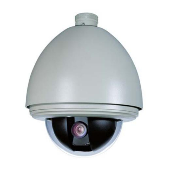
- Page 1 PowerDome PRO Installation manual This manual covers the installation and programming of the Vista PowerDome PRO series of High Speed PTZ domes Manual version – V3.6...
- Page 2 PowerDome PRO manual V3-6...
- Page 3 This document is intended to provide accurate information. However, the information contained herein is subject to change without notice. Vista, in keeping pace with technological advances, is a company committed to product innovation. Therefore, it is difficult to ensure that all information provided is entirely accurate and up-to-date. Vista...
- Page 4 PowerDome PRO manual V3-6...
-
Page 5: Table Of Contents
Contents Description Features Operation Requirements Product Contents Product Contents Installation Preparations Cable Requirements Cable Requirements Power Requirements Power Cable Size and Length Housing and Cabling Installation options Mounting and Housing Styles In-Ceiling Housing Installation Surface-Mount Housing Installation Wall-Mount Housing Installation (VPP-WM) Pendant / Wall Mount Adaptor Collar Pendant / Wall Mount Adaptor Collar Corner-Mounting (VDM-CMAg) - Page 6 3.3 White Balance 3.4 Backlight Mode 3.5 Field Noise Reduce 3.6 FNR Level 3.7 Day/Night Mode 4. Pan/Tilt Setup 4.1 Speed Magnifier 4.2 Proportional PT 4.3 Max Vertical Angle 4.4 Set North 5. Function Setup 5.1 Preset Setup 5.2 Tour Setup 5.3 Learn Tour Setup 5.4 Autopan Setup 5.5 Area Setup...
- Page 7 (Monday through Friday, excluding bank holidays, between 8a.m. and 7p.m.). +44 (0) 118 912 5000. 210 Wharfedale Road Winnersh Triangle, WOKINGHAM. Berks. RG41 5TP www.vista-cctv.com for our on line library. tsg@norbain.com for technical support Note: You should be at the equipment and ready with details before calling technical support.
-
Page 8: Description
Description The PowerDome PRO series is a variable speed PTZ (pan/tilt/zoom) dome camera used in CCTV systems for discreet surveillance of a remote area. Its operational set-up configurations are customised and stored within its own on-board programmable non- volatile memory both in the housing and camera. The PowerDome PRO is programmed... - Page 9 Figure 3 PowerDome PRO manual V3-6...
-
Page 10: Product Contents
Product Contents The PowerDome PRO domes consist of the following: • Housing • PTZ camera assembly • Dome • Installation and user manuals Inspect the packages and contents for visible damage. If any components are damaged or missing, do not use the unit;... - Page 11 Board Type Name of Board Telemetry type VPP-RS485 Vista, Pelco D and Pelco P RS485 VPP-Vista -C Vista Coax VPP-BBV-C BBV coax Protocol Board VPP-PELCO-C Pelco coax VPP-PHILIPS Philips RS422 Telemetry VPP-AD AD Manchester code NOTE: The protocol board should be inserted into JP2 and JP3; these can be found on the hinged power board within the dome housing.
-
Page 12: Cable Requirements
The video cable carries the video signal to the remote viewing site. If sending video via coaxial cable, a 75Ω pure copper c oaxial cable is recommended for distances up to 250m. The PowerDome PRO series is powered by 24V AC. To determine the cable size, please refer to the Power Cable Size and Length on the page 12. -
Page 13: Housing And Cabling Installation Options
Housing and Cabling Installation options Mounting and Housing Styles ..................13. In-Ceiling Housing Installation..................14. Surface-Mount Housing Installation................17. Wall-Mount Housing Installation (VPP-WM)..............20. Pendant/Wall Mount Adapter Collar................23. Corner-Mounting (VDM-CMAg)..................24. Side Pole-Mounting (VDM-EPMAg)................25. Parapet-Mounting (VPP-ESM)…................... 26. PowerDome PRO manual V3-6... -
Page 14: Mounting And Housing Styles
Mounting and Housing Styles There are three basic mounting types: Wall/Pendant, In-ceiling and Surface mount; the Wall/Pendant mounts come as either: Internal, External or Vandal Resistant styles. NOTE: All installation mounting structures must be able to withstand at least 4-times the weight of the dome. Figure 4 Basic mounting styles Surface-mount Wall/Pendant mount... -
Page 15: In-Ceiling Housing Installation
In-Ceiling Housing Installation Follow the instructions given here for In-ceiling housings. CAUTION: The In-Ceiling housing is for indoor applications only. Do not expose it to moisture, or the unit may become damaged. CAUTION: For all installations, heed the following cautions. Complete all installation steps before supplying power to the dome. -
Page 16: Installing The Housing
Installing the housing Once the surface has been prepared, the housing can be installed. To install the housing, see [Figure 8 to 12] and do the following: Unfasten the power board holder. [Figure 8] Loosen the bolt and the power board holder swings away from the housing bracket. Prepare the cables. - Page 17 Figure 8. Figure 9. Figure 10. Figure 11. Figure 12. Figure 14. Figure 13. Figure 15. PowerDome PRO manual V3-6...
-
Page 18: Surface-Mount Housing Installation
Surface-Mount Housing Installation Follow the instructions given here for the surface-mount housing. Preparing the mounting surface CAUTION: For all installations, heed the following cautions. Complete all installation steps before supplying power to the dome. To ensure proper operation of a PTZ unit, ensure the mount is level. For safety, the mounting surface, hardware and procedure used for securing the dome must support the weight of the dome, cables and any structural or environmental vibration according to local regulations. - Page 19 [Figure 16] [Figure 17] [Figure 18] [Figure 19] [Figure 20] [Figure 21] PowerDome PRO manual V3-6...
- Page 20 [Figure 22] [Figure 23] [Figure 24] [Figure 25] PowerDome PRO manual V3-6...
-
Page 21: Wall-Mount Housing Installation (Vpp-Wm)
Wall-Mount Housing Installation (VPP-WM) Cables are run down through the cable entry hole and the dust seal. Take care to avoid damaging the dust seal during installation. Preparing the mounting surface CAUTION: For all installations, heed the following cautions. Complete all installation steps before supplying power to the dome. To ensure proper operation of a PTZ unit, ensure the mount is level. - Page 22 [Figure 26] [Figure 27] [Figure 28] [Figure 29] [Figure 30] [Figure 31] IMPORTANT Please use PTFE tape to ensure sealing. Bolt PTFE Video RS485 Alarm Heater Power Supply Power PowerDome PRO manual V3-6...
- Page 23 [Figure 32] [Figure 33] PCB Board Heater Assembly [Figure 34] [Figure 35] Security Chain Holder Security Chain [Figure 36] PowerDome PRO manual V3-6...
-
Page 24: Pendant / Wall Mount Adaptor Collar
Pendant / Wall Mount Adaptor Collar This collar is supplied in order to allow installation of the PowerDome Pro series onto the Swan Neck (VDM- TM) and pendant drop brackets such as the (VDM-P250). It also ensures backward compatibility with existing PowerDome installations. -
Page 25: Corner-Mounting (Vdm-Cmag)
Corner-Mounting (VDM-CMAg) Preparing the mounting surface CAUTION: For all installations, heed the following cautions. Complete all installation steps before supplying power to the dome. To ensure proper operation of a PTZ unit, ensure the mount is level. For safety, the mounting surface, hardware and procedure used for securing the dome must support the weight of the dome, cables and any structural or environmental vibration according to local regulations. -
Page 26: Side Pole-Mounting (Vdm-Epmag)
Side Pole-Mounting (VDM-EPMAg) Preparing the mounting surface CAUTION: For all installations, heed the following cautions. Complete all installation steps before supplying power to the dome. To ensure proper operation of a PTZ unit, ensure the mount is level. For safety, the mounting surface, hardware and procedure used for securing the dome must support the weight of the dome, cables and any structural or environmental vibration according to local regulations. -
Page 27: Parapet-Mounting (Vpp-Esm)
Parapet-Mounting (VPP-ESM) Preparing the mounting surface CAUTION: For all installations, heed the following cautions. Complete all installation steps before supplying power to the dome. To ensure proper operation of a PTZ unit, ensure the mount is level. For safety, the mounting surface, hardware and procedure used for securing the dome must support the weight of the dome, cables and any structural or environmental vibration according to local regulations. -
Page 28: Menu Operation
Menu Operation Operation Instruction The following instructions are written with the assumption that the unit is being controlled via a Vista VKBD4 keyboard controller. The commands may vary if another manufacturer’s control system is being used. Accessing the Unit Menu... -
Page 29: Menu Tree
System setup and Lens Setup Menu Tree See following pages for rest of menu structure PowerDome PRO manual V3-6... - Page 30 Camera Setup and Pan/Tilts Setup menus Menu Tree – Page 2 See following pages for rest of menu structure PowerDome PRO manual V3-6...
- Page 31 Function Setup menus Menu Tree – Page 3 See following pages for rest of menu structure PowerDome PRO manual V3-6...
- Page 32 Privacy setup and Alarm Setup Menus Menu Tree – Page 4 PowerDome PRO manual V3-6...
-
Page 33: Menu Settings
Menu Settings To enter the menus of the VPP, press and hold the Camera Key, while holding the camera key down, press and release the Mode key. A Screen requesting a password will appear. The default password is 6 zeros (000000) The main menu screen will appear. -
Page 34: Device Setup
1.1 Device Setup Main menu → System Setup → Device Setup 1. DEVICE ID: This identifies the current unit’s ID number. Each unit has its unique ID ranging from 001 to 255 (255 is default broadcast ID). This can be set via the menus only if the DIP switches are set to programmable mode, all switches set to ON. -
Page 35: Display Setup
f) If the OSD menu shows as below then reset the unit ID. This is because the unit ID is not identical with the setting. Thus the unit can not be controlled. g) After correcting the unit ID, call preset No.1 to confirm the resetting. h) If the OSD menu appears as below, it means that the current ID is hard address and cannot be programmed. - Page 36 Title Display This allows you to program how titles are displayed on the monitor. The following titles can be set: 1. Device Title (ON, OFF, 2s-60s): Displays the unit title. 2. Preset Title (ON, OFF, 2s-60s): Displays preset title when calling up the preset. 3.
-
Page 37: Change Password
Other Display 1. Zoom Position (ON, OFF, 2s-60s): Display time of the zoom times. 2. Direction Disp. (ON, OFF, 2s-60s): Display time of direction indicator. 3. Alarm Display (ON/OFF): Display the active alarm inputs. 4. System Time (ON/OFF): Display the current system time. 5. -
Page 38: Language Select
Note: The default password is 000000. If it is changed, the password protection is activated. It will be necessary to enter the password whenever you want to access the OSD menu. 1.4 Language Select Main menu → System Setup → Language Setup The language for the on-screen menus is selectable. -
Page 39: System Restart
1.6 System Restart Main menu → System Setup → System Restart Once the factory Default selection is made, a message about requesting the calling of Preset 1 to accept or Preset 2 to cancel the request will appear. NOTE: Restarting the system will not change any settings. 1.7 About Main menu →... -
Page 40: Clear All
1.8 Clear All Main menu → System Setup → Clear All Call preset 1 will clear all presets, all tours, all learns, all areas, all auto -pans, all privacy and all alarm setup. Call preset 2 will cancel this setup. PowerDome PRO manual V3-6... -
Page 41: Lens Setup
2. Lens Setup Main menu → Lens Setup 2.1 Zoom Speed This function allows the user to define how fast the VPP will zoom. Available settings include the following: High: Fast zooming speed Low: Slower zooming speed 2.2 Max Digital Zoom Max Digital zoom magnifies the picture by duplicating pixels. -
Page 42: Auto Recovery
2.6 Auto Recovery This is used to configure the auto focus and auto iris resuming settings. Four settings are available: All: Moving the Joystick restores both the Auto Focus and Auto Iris functions None: Moving the joystick doe not restore the Auto focus or Auto Iris function Iris: Moving the Joystick only restores the Auto Iris function Focus: Moving the Joystick only restores the Auto Focus function... -
Page 43: Camera Setup
3. Camera Setup Main menu → Camera Setup 3.1 Picture Freeze This feature is to reduce unnecessary data traffic in web application and save storage space on DVRs. Available selections include the following: ON: The current image is frozen when a preset is called, so picture freezes till the dome reaches the next preset position. -
Page 44: White Balance
The camera will hold the Iris level selected and vary other parameters to achieve the best picture. Iris settings available are: F1.6, F2.2, F3.2, F4.4, F6.4, F8.8, F12, F17, F24, and F34 AGC: The camera will hold the AGC level selected and vary other parameters to achieve the best picture. AGC values available are: 0dB, 6dB, 12dB, 18dB, 24dB, 30dB. -
Page 45: Backlight Mode
3.4 Backlight Mode This sets backlight compensation. If the backlight is bright, the objects in the centre of the picture may be dark. The unit can automatically adjust the brightness of the whole image according to the brightness of centre point. OFF: This function is disabled. -
Page 46: Day/Night Mode
3.7 Day/Night Mode 1. Day/Night mode This automatically switches between colour and monochrome mode in accordance with the environment illumination. Four settings are available: Auto: The Dome will automatically change from Colour to Mono at user defined level Day: The dome will remain in Colour mode Night: The dome will remain in Monochrome mode Time: The dome will change modes at user defined times. -
Page 47: Pan/Tilt Setup
4. Pan/Tilt Setup Main menu→ Pan/Tilt Setup 4.1 Speed Magnifier Some protocols speed control vary; the Speed Magnifier allows the speed to be made faster or slower. The selections are as follows: X1: Original speed (default setting) 32: Times faster than original speed. 32: Times slower than original speed. -
Page 48: Set North
4.4 Set North The camera can display the direction it is facing in degrees relative to a user defined position. When Set North is selected within the menus the above box will appear, move the VPP to a direction that is to be defined as North (Zero degrees) and call preset 1. -
Page 49: Function Setup
5. Function Setup Main menu → Function Setup 5.1 Preset Setup Main menu → Function Setup →Preset setup This allows you to program a preset with auto pan, tilt, and focus and iris settings. Once programmed, entering the number and press PRESET button on your controller will automatically call up the preset. As many as 220 preset positions can be programmed. - Page 50 This allows you to set a new preset position. Select this option and follow the on screen instructions. Move to the desired position and zoom to a suitable level, call preset 1 to save the current preset, call preset 2 to cancel. 4.
-
Page 51: Tour Setup
5.2 Tour Setup Main menu → Function Setup →Tour setup A ―tour‖ is defined as a sequence of movements from one preset to the next at a fixed speed, with pause for a specific time at each preset. Up to 4 tours can be stored. Each can store 32 presets at maximum. - Page 52 5. Speed Between This option allows the setting of the Pan speed that the VPP travels between preset positions during the tour. The options are: Low (approx 15 /Sec), Medium (approx 30 /Sec) or High (approx 50 /Sec). 6. Wide Angle Between This option allows the camera to be set to zoom out to its widest angle before moving to the next preset position.
-
Page 53: Learn Tour Setup
5.3 Learn Tour Setup Main Menu → Function Setup → Learn setup A learn tour records and repeats a series of pan, tilt, zoom functions. This allows the operator to program a smooth path for the VPP to follow. Up to four learn tour modes can be set. Each of them can have a duration of up to 180s. 1. -
Page 54: Autopan Setup
4. Run Mode: When the Learn Tour command is sent, the dome can be set to either run the Le arn Tour Once or Continuously. 5. Test Learn Tour: This allows the operator to test the Learn tour from within the menus. 6. - Page 55 4. Set Right Limit: This sets the right edge of the area to be scanned. . Follow the on screen instructions. 5. Default Speed: This sets the scanning speed ranging from 001 to 255. 6. Autopan CMD: The user can define the command that will start the Autopan tour. Default is AUX6. 7.
-
Page 56: Area Setup
5.5 Area Setup Main menu Function Setup Area Setup An Area is a segment of the view between 2 defined pan positions. The title can be edited and will appear on screen when the unit enters this area. Up to four Areas can be set. 1. -
Page 57: Schedule Setup
5. Delete Current Area: The current Area is deleted. 5.6 Schedule Setup Main menu → Function Setup → Schedule Setup This function allows the unit to run specified functions according to a user definable scheduled. 1. Schedule No: There are 8 definable timed events available. 2. - Page 58 Preset (1~220): Enable Preset function. Tour (1~4): Enable Tour function. Learn tour (1~4): Enable Learn tour function. Autopan (1~4): Enable Autopan function. NOTE: 1. Specified times can not be overlapped between running channels. This will prevent any action from being executed 2.
-
Page 59: Home Setup
5.7 Home Setup Main menu → Function Setup → Home Setup This function makes the unit automatically run an assigned function after a predetermin ed period when no command is received. Home Time: This is the time period, in seconds; the VPP will wait, after the last operator command, till it performs the Home operation specified below. -
Page 60: Privacy Setup
6. Privacy Setup Main menu → Privacy Setup This function uses grey masks to shield where monitoring may intrude on privacy, such as a resident’s window, a toilet, etc. 1. Privacy Mask Number: It sets the privacy mask number, ranging from 001 to 008. 2. - Page 61 3. Active: This sets whether each mask is displayed on the screen or not. 4. Show Next Mask: It automatically shows the next mask. If the next mask is not set, an alert message will be displayed. 5. Delete Current Mask: The current mask is deleted.
-
Page 62: Alarm Setup
7. Alarm Setup Main menu → Alarm Setup The VPP has 4 built in Alarm Inputs and 2 relay outputs which can be configured in the following manner: 1. Alarm Input No.: This set the alarm input to be configured. 2. - Page 63 7. Set Arm/Disarm Time Arm Time This set the time that the alarm input will be armed from Disarm Time This sets the time at which the Alarm input will be come inactive. 8. Alarm Behaviour 1). Return After Clear This allows the operator to configure how the VPP behaves after the alarm has cleared.
- Page 64 The manual priority mode allows the dome to be set to ignore, for a preset time period, subsequent alarm inputs once the first has been received. This gives the opportunity for an operator to manually take control and follow an intruder, without further alarms overriding the manual control, and sending the VPP to a preset position.
-
Page 65: Appendix I: Dip Switch & Jumper Settings
The last two (7 – 8) bits on SW2 are for the baud rate. Default is 9600bps. NOTE: If you are using Vista Coax, BBV Coax, AD or PHILIPS protocol please set the baud rate to 19200 bps = ON... -
Page 66: Protocol Telemetry Boards
Protocol Telemetry Boards The PowerDome PRO series of domes comes supplied as standard with 2 Telemetry protocol boards. These two boards will allow the following common protocols to operate the domes: 1. RS485 Board – Vista PD, Pelco D and Pelco P 2. - Page 67 3 and 4 Pin Telemetry boards Dependant on the telemetry type the board will have rather 3 or 4 pairs of pins protruding from it as well as an 8 pin socket. Ensure that the pins are correctly loc ated and that the board is ―square‖ to the lower Power board, see images below for clarification.
-
Page 68: Dome Address Setting
Dome Address Setting The control commands contain the target dome’s ID. The dome will only react to the commands sent to its own address or broadcast address. Each dome must be assigned an individual address. There are three kinds of IDs applicable for the domes: Switch Number (SW1) Hard ID: Hard ID is set via DIP SW1, it can not be changed from the OSD menu. - Page 69 = ON Dome ID dip switch settings Dome ID dip switch settings Switch Number Switch Number ...
- Page 70 = ON Dome ID dip switch settings Dome ID dip switch settings Switch Number Switch Number ...
- Page 71 = ON Dome ID dip switch settings Switch Number ...
-
Page 72: Coax Or Twisted Pair Settings
COAX or Twisted Pair Settings The Vista Speed dome supports two common types of cables to transmit video signal, coaxial cable and twisted pair cable. The type of video output is controlled by jumpers 16 and 17 (JP16 and JP17) on the drop down board within the housing. -
Page 73: Alarm Input Connections
Alarm Input Connections There are 7 Alarm inputs available on the main board within the dome housing the details are shown below: Alarm Input 1 Video Output Alarm Input 2 Video Ground Alarm Input 3 RS485 + Alarm Input 4 RS485 - Alarm Input 5 Reserved... -
Page 74: Appendix Ii: Rs-485 Bus Basic Knowledge
Appendix II: RS-485 Bus Basic Knowledge Characteristics of RS485 Bus As specified by RS485 standards, RS485 Bus is of half-duplex data transmission cables with characteristic impedance as 120Ω. The maximum load capacity is 32 unit loads (including main controller and controlled equipment). - Page 75 Connections via a Star Configuration It is necessary when installing a Star Configuration to use a Dome Star Driver, such as the Vista VSD/16 a 16-channel Star Driver for RS-485 control. This will give reliable RS- 485 data transmission. PowerDome PRO manual V3-6...
-
Page 76: Appendix Iii: Lightning & Surge Protection
Appendix III: Lightning & Surge Protection The Vista Dome range incorporates TVS lightning protection to prevent it from being damaged by strike of up to 4,000V and impulse signals such as a surge; but it is also necessary to abide by the following precautions to ensure electrical safety. -
Page 77: Appendix Iv: Trouble Shooting & Cleaning
Appendix IV: Trouble Shooting & Cleaning This chapter provides information to help you troubleshoot problems, perform simple preventive maintenance procedures and contact technical support in case you need assistance with your Vista equipment. In this chapter: Troubles Shooting ............76. -
Page 78: Cleaning The Dome Bubble
Cleaning the Dome Bubble Use the following procedures for cleaning the dome. Be aware that the interio r of the dome requires extra care in cleaning. Use only the procedures provided below. CAUTION: To prevent damage, do not touch the bubble with your bare hands, do not place the bubble face down on any surface, and protect the bubble from dust. -
Page 79: Appendix V Installing The External Psu
Appendix V Installing the External PSU VPSU243EXT OUTDOOR POWER SUPPLY The VPSU243EXT is a 24 VAC outdoor power supply designed for use with a pendant-mount weatherproof Top Cat. It provides enough power (100 VA) to operate the dome’s pan/tilt drive, camera and heater/fan. The VPSU243EXT can be attached directly to a wall, or it can be mounted on to either the VDM-CMAg Corner-Mount Bracket or the VPD-EPMAg Pole- Mount Bracket. -
Page 80: Appendix Vi - Back Box Memory
Appendix VI - Back Box Memory The Power Board located in the dome housing retains the settings of the dome – Presets, Tours etc. In the event of the camera Yoke have to be replaced, these original settings will automatically be loaded into th e new camera Yoke ( assuming the Yoke model is the same) on initial power up and initialisation. - Page 81 Installer Notes: PowerDome PRO manual V3-6...
- Page 83 Vista Wharfedale Winnersh Triangle WOKINGHAM Berkshire RG41 5PT Tel: +44 (0) 118 912 5000 Fax: +44 (0) 118 912 5001 www.vista-cctv.com PowerDome PRO manual V3-6...
Need help?
Do you have a question about the PowerDome PRO Series and is the answer not in the manual?
Questions and answers