AVer SF2012H series Quick User Manual
Hide thumbs
Also See for SF2012H series:
- User manual (63 pages) ,
- Quick installation manual (2 pages) ,
- User manual (65 pages)

Subscribe to Our Youtube Channel
Related Manuals for AVer SF2012H series


Summary of Contents for AVer SF2012H series
- Page 1 SF2012H IP Camera Series SF2012H/SF2012H-B/SF2012H-C SF2012H-D/SF2012H-DV Quick User Guide...
-
Page 2: Table Of Contents
Table of Contents Camera Introduction ....................1 Box Type IP Camera(SF2012H) ..............1 Package Contents ..................1 Hardware Installation .................. 2 Factory Default .................... 2 Bullet Type IP Camera (SF2012H-B) ............. 3 Package Contents ..................3 Hardware Installation .................. 5 Factory Default .................... - Page 3 Using DHCP Server/Router Network ................ 22 Using NON-DHCP Server/Router Network ............... 23 Connecting the IP Camera ..................26 FCC NOTICE (Class B) ..................... 27 COPYRIGHT ........................27 NOTICE ..........................27 WARNING .......................... 27 Limited Warranty ......................28 Governing Law and Your Rights ..................29...
-
Page 5: Camera Introduction
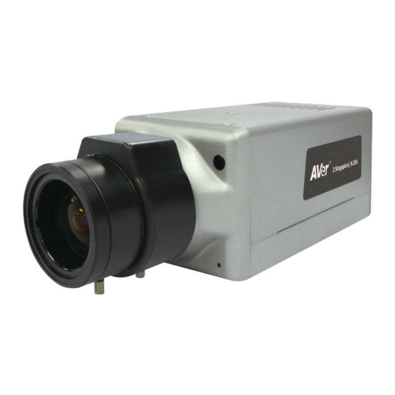
Before Installation Before installation, please be sure to read this quick installation guide and user’s manual carefully to complete the installation. Camera Introduction The following section introduces package contents, hardware installation, factory default reset, and SD card Compatibility List of each type camera. 1. -
Page 6: Hardware Installation
1.2 Hardware Installation Connect the power adapter and connect the IP camera to local network with the Ethernet cable. 1.3 Factory Default 1. Please follow the below instructions if the user name, password, and IP address are lost. 2. First, unplug the power adapter. Then, press the button in the back of IP camera as shown in figure. -
Page 7: Bullet Type Ip Camera (Sf2012H-B)
2. Bullet Type IP Camera (SF2012H-B) Package Contents Item Descriptions 1. SF2012H-B 2. Stand 3. Accessory pack 4.. RJ45 socket 5. Ethernet cable 6. Power Adaptor(DC 12V/1A) (Optiona) - Page 8 Item Descriptions 7. CD (User’s Manual and Quick Guide included) **If any of the above items are missing, please contact your dealer immediately.
-
Page 9: Hardware Installation
Hardware Installation Connect a power adapter and IP camera to PC or local network. Pink default setting wire 3.5mm Phone Jack (Audio Input, Red) 3.5mm Phone Jack (Audio Output, Green) I/O Control Instruction I/O terminal connector – used in application, for e.g., motion detection, event triggering, alarm notifications. - Page 10 [Example] RELAY INSTALLATION EXAMPLE 1 Trigger a “Normal OFF” (Normal Open) alarm siren on when event/motion occur: RELAY INSTALLATION EXAMPLE 2 Trigger the “Normal ON” (Normal Close) indoor illumination off when event / motion occur:...
-
Page 11: Factory Default
Factory Default 1. Removing an Ethernet cable. 2. Plugging “a pink default cable” into “GND”. 3. Plug power cable. 4. When camera starts again, please remove the pink default cable and plug Ethernet cable for new setting. 5. Release the button when camera finishes proceed. 6. -
Page 12: Cube Ip Cameras (Sf2012H-C)
3. Cube IP Cameras (SF2012H-C) Package Contents Item Descriptions 1. SF2012H-C 2. Stand box 3. Ethernet cable 4. Power Adaptor(DC 12V/1A) (Optional) 5. CD (User’s Manual and Quick Guide included) **If any of the above items are missing, please contact your dealer immediately. -
Page 13: Hardware Installation
Hardware Installation 1. Connect power adapter. 2. Connect IP camera to PC or network with Ethernet cable. LED indicator Connect Ethernet cable Connect Power adapter 3. Set up the network configurations according to the network environment. Factory Default 1. To recover the default IP address and password, please follow the following steps. 2. -
Page 14: Dome Type Ip Camera
4. Dome Type IP Camera Package Contents 4.1.1 SF2012H-D Item Descriptions 1. SF2012H-D 2. Accessory pack 3. Ethernet cable 4.. RJ45 socket 5. Power Adaptor(DC 12V/1A) (Optional) 6. CD (User’s Manual and Quick Guide included) **If any of the above items are missing, please contact your dealer immediately. -
Page 15: Sf2012H-Dv
4.1.2 SF2012H-DV Item Descriptions 1. SF2012H-DV 2. Accessory pack 3. Ethernet cable 4. RJ45 socket 5. Power Adaptor(DC 12V/1A) (Optional) 6. CD (User’s Manual and Quick Guide included) **If any of the above items are missing, please contact your dealer immediately... -
Page 16: Hardware Installation
Hardware Installation 4.2.1 SF2012H-D Connect a power adapter and IP camera to PC or local network. 3.5mm Phone Jack (Audio Input, Red) 3.5mm Phone Jack (Audio Output, Green) 3. I/O Control Instruction I/O terminal connector – used in application, for e.g., motion detection, event triggering, alarm notifications. - Page 17 [Example] RELAY INSTALLATION EXAMPLE 1 Trigger a “Normal OFF” (Normal Open) alarm siren on when event/motion occur: RELAY INSTALLATION EXAMPLE 2 Trigger the “Normal ON” (Normal Close) indoor illumination off when event / motion occur:...
-
Page 18: Sf2012H-Dv
SF2012H-DV 4.2.2 1. Connect a power adapter and IP camera to PC or local network. 2. 3-Axis Gimbals Adjustments Once the users open the case, the gimbals adjustment offers the convenience method to install on the wall. The pan, tilt, and rotation are provided in this model. The users can adjust the gimbals with Pan 175 degrees, tilt 75 degrees, and rotation 180 degrees respectively. - Page 19 4. I/O Control Instruction I/O terminal connector – used in application, for e.g., motion detection, event triggering, alarm notifications. It provides the interface to: Digital Input (GND+Alarm) : An alarm input for connecting devices that can toggle between an open and closed circuit, for 1.
- Page 20 RELAY INSTALLATION EXAMPLE 2 Trigger the “Normal ON” (Normal Close) indoor illumination off when event / motion occur:...
-
Page 21: Factory Default
Factory Default SF2012H-D 4.3.1 1. If the user name, password, and IP address are lost, please follow the following instructions. 2. Unplug the power adapter first. Then, press the following button in the back of IP camera. Reset button 3. Plug in the power adapter and do not release the button during the IP camera booting. 4. -
Page 22: Sf2012H-Dv
SF2012H-DV 4.3.2 1. To recover the default IP address and password, please follow the following steps. 2. Remove power, press and hold the button. Please refer to the picture below. Reset button 3. Power on the camera. Don’t release the button during the system booting. 4. -
Page 23: Sd Card Compatibility List
SD card Compatibility List The SF2012H series IP cameras are compliant with SD/SDHC card and to ensure recording quality, and please use memory cards over 2G and Class 4 above (Max. 32G) Micro SD/SDHC card SD/SDHC Transcend SDHC class4 16GB... -
Page 24: Monitor Setting
Monitor Setting 1. Right-click on the desktop. Select “ Properties” 2. Change “Color quality” to “Highest (32-bit)”. -
Page 25: Ip Assignment
III. IP Assignment 1. Use the software, “IP Installer” to assign the IP address of the IP camera. The software is in the attached software CD. 2. IP installer supports two languages IPInstallerCht.exe: Traditional Chinese version IPInstallerEng.exe: English version 3. There are 3 kinds of IP configuration. Fixed IP (Public IP or Virtual IP) DHCP (Dynamic IP) DHCP server/router network automatically assigns IP addresses to devices. -
Page 26: Using Dhcp Server/Router Network
IP Installer configuration: 6. IP Installer will search all IP cameras connected on the LAN. The user can click “Search Device” to search again. 7. Click one of the IP cameras listed on the left side. The network configuration for this IP camera will show on the right side. -
Page 27: Using Non-Dhcp Server/Router Network
Using NON-DHCP Server/Router Network In Non-DHCP server/router network, the static IP address must be assigned to the device each time when adding another IP camera to the network; the default IP address of the current one must be changed to avoid conflict. Please make sure the Subnet of the PC’s IP address and the IP camera’s IP address are the same. - Page 28 IP camera IP addresses: 8. A quick way to access remote monitoring is to left-click the mouse twice on a selected IP camera in “Device lists” in IP Installer. Upon doing so, the Internet Explorer browser should open.
- Page 29 9. Then, please key in the default “User name” and “Password”, both of which are “admin”.
-
Page 30: Connecting The Ip Camera
IV. Connecting the IP Camera Launch the Internet Explorer browser, type the IP address of the IP camera in the address field. It will show the following dialogue box. Key-in the”ID” and “Password”. The default”ID” and “Password” are both “admin”. Once connected to the IP camera, the following program interface will appear. -
Page 31: Fcc Notice (Class B)
© 2012 AVer Information Inc. All rights reserved. All rights of this object belong to AVer Information Inc. Reproduced or transmitted in any form, or by any means without the prior written permission of AVer Information Inc. is prohibited. AVer Information Inc. -
Page 32: Limited Warranty
You as the original purchaser. Except for the foregoing, the Product is provided “AS IS.” In no event does AVer warrant that You will be able to operate the Product without problems or interruptions, or that the Product is suitable for your purposes. Your exclusive remedy and the entire liability of AVer under this paragraph shall be, at AVer’s option, the repair or replacement... -
Page 33: Governing Law And Your Rights
Governing Law and Your Rights This warranty gives you specific legal rights; You may also have other rights granted under state law. These rights vary from state to state.
Need help?
Do you have a question about the SF2012H series and is the answer not in the manual?
Questions and answers