Motorola U9 Service Manual
Digital wireless telephone gsm 850/900/1800/1900 gprs/edge
Hide thumbs
Also See for U9:
- User manual (92 pages) ,
- Quick start manual (40 pages) ,
- User manual (80 pages)
Table of Contents
Advertisement
Quick Links
Download this manual
See also:
User Manual
Advertisement
Table of Contents

Related Manuals for Motorola U9


Summary of Contents for Motorola U9
- Page 1 Level 1 & 2 Service Manual 6809513A81-A Digital Wireless Telephone GSM 850/900/1800/1900 GPRS/EDGE...
- Page 2 MOTOROLA and the Stylized M Logo are registered in the US Patent & Trademark Office. All other product or service names are the property of their respective owners. © Motorola, Inc. 2007, 2008. All rights reserved. Mobile Devices Business, 800 West Sunrise Boulevard...
-
Page 3: Table Of Contents
Level Service Manual Contents Contents Introduction ................5 Product Identification . - Page 4 Contents April 01, 2008...
-
Page 5: Introduction
Available on a contract basis, Motorola Inc. offers comprehensive maintenance and installation programs which enable customers to meet requirements for reliable, continuous communications. To learn more about the wide range of Motorola service programs, contact your local Motorola products representative or the nearest Customer Service Manager. Product Identification Motorola products are identified by the model number on a label usually located under the battery. -
Page 6: Computer Program Copyrights
The Motorola products described in this manual may include Motorola computer programs stored in semiconductor memories or other media that are copyrighted with all rights reserved worldwide to Motorola. Laws in the United States and other countries preserve for Motorola, Inc. certain exclusive rights to the copyrighted... -
Page 7: Warranty Service Policy
Customer’s original phones will be repaired but not refurbished as standard. Appointed Motorola Service Hubs will perform warranty and non-warranty field service for level 2 (assemblies) and level 3 (limited PCB component). Motorola High Tech Centers will perform level 4 (full component) repairs. -
Page 8: Parts Replacement
When ordering replacement parts or equipment, include the Motorola part number and description used in the service manual. When the Motorola part number of a component is not known, use the product model number or other related major assembly along with a description of the related major assembly and of the component in question. -
Page 9: Specifications
Level 1 and 2 Service Manual Specifications General Function Specification Frequency Range GSM 850 824-848 MHz Tx 869-893 MHz Rx Frequency Range GSM 900 880-915 MHz Tx (with EGSM) 925-960 MHz Rx Frequency Range DCS 1800 1710-1785 MHz Tx 1805-1880 MHz Rx Frequency Range PCS 1900 1850-1910 MHz Tx 1930-1990 MHz Rx... - Page 10 U9 GSM Speech Coding Functions Specification Speech Coding Type Regular pulse excitation/linear predictive coding with long term prediction (RPE LPC with LTP) Bit Rate 13.0 kbps Frame Duration 20 ms Block Length 260 bits Classes Class 1 bits = 182 bits; Class 2 bits = 78 bits Bit Rate with FEC Encoding 22.8 kbps...
-
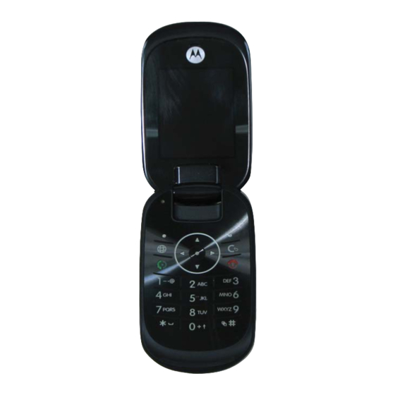
Page 11: Product Overview
GSM 850 MHz, GSM 900 MHz, 1800 MHz Digital Cellular System (DCS), and PCS 1900 MHz bands. U9 telephones have a clam form factor. They feature an externally viewable 1.45" 128 x 160 262K OLED CLI display for caller identification with date/time, and an internal 2.0"... - Page 12 U9 GSM • WMV v10 • WMV v9 • RV v9 • H.264 • H.263 • MPEG4 Display • Main display 2.0" QVGA 262K TFT • CLI display 1.45" 128 x 160 262K OLED Memory • 20 MB internal memory Imaging •...
- Page 13 Level 1 and 2 Service Manual Personal Information Management The U9 telephone contains a built in calendar with date book reminders and phonebook that can be synchronized easily to a computer. 6809513A81-A April 01, 2008...
-
Page 14: General Operation
U9 GSM General Operation Controls, Indicators, and Input/Output (I/O) Connectors The U9 controls are located on the front and sides of the device, and on the keyboard, as shown in Figures 1 and 2. Internal Earpiece Menu Key Main Display... - Page 15 Level 1 and 2 Service Manual Volume Keys Voice Command Key Smart Key EMU/Headset Connector Figure 3. Telephone Controls and Indicators Locations (Sides) Indicators, in the form of icons, are displayed on the LCD (see Figure 4). Figure 4. Main Screen Icon Display Signal Strength Indicator —...
-
Page 16: Menu Navigation
LowBattery. Menu Navigation U9 telephones are equipped with an icon and graphical-based user interface. All of the phone’s features can be accessed with a 5-way navigation key that allows you to move easily through menus and select menu items. -
Page 17: Battery Information
Level 1 and 2 Service Manual Liquid Crystal Display (LCD) The LCD provides an large color display with user-adjustable brightness settings for optimum readability in all light conditions. The large 128 x 160 65K TFT pixel display provides room for entering text, viewing graphics, tapping icons, and system prompts. -
Page 18: Tools And Test Equipment
Generic press tool CLI lens. 1. To order in North America, contact Motorola Aftermarket and Accessories Division (AAD) at (800) 422-4210 or FAX (800) 622-6210; Internationally, AAD can be reached by calling (847) 538-8023 or faxing (847) 576-3023. 2. Not available from Motorola. To order, contact: AMS Software & Elektronik GmbH, c/o Holger Grube, Lise-Meitner- Straße9 D-24941 Flensburg Tel.: +49-461-90398-0 Fax: +49-461-90398-50. -
Page 19: Disassembly
Disassembly Disassembly The procedures in this section provide instructions for the disassembly of a U9 telephone. Tools and equipment used for the phone are listed in Table 1, preceding. Many of the integrated devices used in this equipment are vulnerable to damage from electrostatic discharge (ESD). -
Page 20: Removing And Replacing The Subscriber Identity Module (Sim)
Disassembly 1 and 2 There is a danger of explosion if the Lithium Ion battery is replaced incorrectly. Replace only with the same type of battery or equivalent as recommended by the battery manufacturer. Dispose of used batteries according to the manufacturer’s instructions. -
Page 21: Removing And Replacing The Housing Screws
Level Service Manual Disassembly Removing and Replacing the Housing Screws This product contains static-sensitive devices. Use anti-static handling procedures to prevent electrostatic discharge (ESD) and component damage. Remove the battery cover, battery, and SIM as described in the previous procedures. In addition to 6 screws, the rear housing assembly is fastened with plastic latches. -
Page 22: Removing The Main Pcb Assembly
Disassembly 1 and 2 Removing the Main PCB Assembly Using the flat tip of the disassembly tool, gently & carefully insert in between the keypad cover and flip knuckle joint as shown below. Slide the disassembly tool around the outline of the keypad cover to release the keypad cover from the Xcvr housing . - Page 23 Level Service Manual Disassembly After revealing the main flex connector, as shown below, carefully pry off the connector using the black disassembly tool. Figure 6. Locating and Separating the Main Flex Connector Lift the PCB assembly away from the housing. To replace, attach the main flex cable onto the PCB assembly.
- Page 24 Disassembly 1 and 2 Clip Spring Removal and Replacement 11. Remove the clip spring screw with a T3 torque driver. Clip Spring Screw v534250 Figure 7. Clip Spring Removal 12. Remove the clip spring from the rear housing. 13. To replace, insert a new clip spring into the rear housing.. Clip Spring v534252 Figure 8.
-
Page 25: Removing The Hinge Assembly
Level Service Manual Disassembly Removing the Hinge Assembly This product contains static-sensitive devices. Use anti-static handling procedures to prevent electrostatic discharge (ESD) and component damage. Remove the battery cover, battery, SIM and PCB from the housing as described in the procedures. -
Page 26: Removing And Replacing The Main Lens
Disassembly 1 and 2 Removing and Replacing the Main Lens Remove the battery cover, battery, SIM, rear housing, transceiver board, front housing as described in the procedures. Using the disassembly tool, insert the tool under the display lens at the top of the flip. Slide the tool around the edges of the display lens to remove the lens. - Page 27 Level Service Manual Disassembly Insert the disassembly tool between the front and rear flip housing to unlatch the flip catches in the sequence shown below. Separate the flip rear & front housing after all catches are being unlatched. Figure 12. Separating the Flip Front Housing from the Flip Rear Housing To replace, align the flip rear housing to the flip assembly and carefully press downwards to engage the 7 latches.
- Page 28 Disassembly 1 and 2 Remove the adhesive liner from the new display lens and use the main lens press fixture (see Figure 13). Press and hold for 15 +/- 1 seconds. Main lens press fixture v527346 Figure 13. Main Lens Press Fixture Replace the front housing, transceiver board, rear housing, SIM, battery &...
-
Page 29: Removal & Replacing The Flip Board Assembly & Display
Level Service Manual Disassembly Removal & Replacing the Flip Board Assembly & Display Remove the battery cover, battery, SIM, rear housing, transceiver board, front housing, flip housing as described in the procedures. Using a tweezer, gently pushing outwards to release the 4 display bracket catches shown below. -
Page 30: Removing The Camera Assembly
Disassembly 1 and 2 Carefully pry the display away from the flip assembly. To replace, carefully align and replace the display onto the flip assembly. Replace the display bracket onto the flip assembly.. Replace the flip housing, front housing, transceiver board, rear housing, SIM, battery and battery cover as described in the procedures. - Page 31 Level Service Manual Disassembly Using the disassembly tool, unseat the flip flex connector from its socket. Figure 17. Unseating the Camera and Flip Flex Connectors After disconnecting the flex connectors, notice that the camera becomes loose and should slide away from the display assembly as shown in figure 18. Figure 18.
- Page 32 Disassembly 1 and 2 To replace, carefully align & lower the flip board assembly onto the flip front housing. Insert the vibrator module into its slot and gently press downwards to ensure it sits properly on the housing. Press the camera module connector into its socket on the flip board assembly. Reconnect the flip flex connector to its socket on the flip board assembly.
-
Page 33: Disassemble Housing Components
Level Service Manual Disassembly Disassemble Housing Components Remove the battery cover, battery, SIM card, rear housing, and transceiver board assembly as described in the procedures. Hold the edge of the antenna as shown in figure 19, take the antenna out of the housing Figure 19. -
Page 34: Subscriber Identity Module (Sim) And Identification
The Mechanical Serial Number (MSN) is an individual unit identity number and remains with the unit throughout the life of the unit. The MSN can be used to log and track a unit on Motorola's Service Center Database. The MSN is divided into 4 sections, as shown in Figure 21. - Page 35 Level Service Manual Subscriber Identity Module (SIM) and Identification International Mobile Station Equipment Identity (IMEI) The International Mobile station Equipment Identity (IMEI) number is an individual number unique to the PCB and is stored within the unit's memory. The IMEI uniquely identifies an individual mobile station and thereby provides a means for controlling access to GSM networks based on mobile station types or individual units.
-
Page 36: Htcmd (Handset Test Command)
HTCMD (Handset Test Command) 1 and 2 HTCMD (Handset Test Command) Enter test command Insert Test SIM Card & Battery into handset. To enter Test Command Screen, Press <Menu> button followed by 048263* Enter Suspend Mode Enter “54”, then select <OK> When “Success”... - Page 37 Level Service Manual HTCMD (Handset Test Command) Display Segment/ Pixel Test Turn On All Pixels to inspect the display grid on LCD Enter 55*2*001 & select <OK>, press O after test. Turn On Checkboard pattern A Enter 55*2*002 & select <OK>, press O after test. Turn On Checkboard pattern B Enter 55*2*003 &...
-
Page 38: Troubleshooting
Troubleshooting 1 and 2 Troubleshooting Troubleshooting Chart Table 3. : Level 1 and 2 Troubleshooting Chart SYMPTOM PROBABLE CAUSE VERIFICATION AND REMEDY 1. Telephone will not turn on or stay on. a) Battery either discharged or Measure battery voltage across a 50 ohm (>1 defective. - Page 39 Level Service Manual Troubleshooting Table 3. : Level 1 and 2 Troubleshooting Chart (Continued) SYMPTOM PROBABLE CAUSE VERIFICATION AND REMEDY d) Transceiver board defective. Forward to an authorized level 3 service center. 6. Receive audio from earpiece speaker is a) Connections to or from transceiver Gain access to the transceiver board assembly weak or distorted.
-
Page 40: Programming: Software Upgrade And Flexing
Troubleshooting 1 and 2 Table 3. : Level 1 and 2 Troubleshooting Chart (Continued) SYMPTOM PROBABLE CAUSE VERIFICATION AND REMEDY 11. Real Time Clock resetting when Lithium button cell in the display board Refer service to a Level 3 service center for standard battery is removed. -
Page 41: Exploded View Diagram
Figure 22. Exploded View Diagram (Flip Assembly) Exploded View Parts List (Flip Assembly) The following part number table is provided only for reference. Please contact your local Motorola parts organization for current part number information. Table 4. Exploded View Parts List (Flip Assembly) Number... -
Page 42: Exploded View Parts List (Main Assembly)
Figure 23. Exploded View Diagram (Main Assembly) Exploded View Parts List (Main Assembly) The following part number table is provided only for reference. Please contact your local Motorola parts organization for current part number information. Figure 24. Exploded View Parts List (Main Assembly) Number... - Page 43 Data Cable Mini USB/USB/Serial SKN6371 Grey EMU data cable SKN6234 Digital Accessories Data Cable TTA AAKN4013 Motorola Phone Tools Phase 4 SVN5539 Music & Entertainment S255 EMU Mono HS SYN1471 Power Travel Charger EMU Rapid Switcher - MEX Portuguese SPN5361...
- Page 44 Troubleshooting 1 and 2 Table 5. Accessories(Continued) Part Description Part Number Travel Charger EMU Rapid Switcher - TWN SPN5270 Standard Car Charger EMU - P310 SYN1630 Vehicle Power Adapter EMU - VC700 SYN0847 P510 VPA EMU High Performance "Loop" SPN5401 Battery BC60 (SC5 Ltd) Li-Ion 900 mAh SNN5781 P320 desktop BOC (battery-only-charge), platform, EMU...
- Page 45 U9 GSM 6809513A81-A 1 and 2 Level 1 and 2 Service Manual INDEX IndexINDEX IM indicators 16 IMEI 35 active line indicator 16 in-call indicator 16 battery LCD 17 charge indicator 17 liquid crystal display (LCD) 17 function 17 Low Battery message 16...
- Page 46 INDEX Product Family U9 GSM serial number mechanical 34 service manual about 6 revisions 7 scope 6 service policy 7 customer support 7 out of box failure 7 product support 7 service procedure ordering replacement parts 8 shut down upon battery removal 17...
- Page 47 Level 1 and 2 Service Manual INDEX 6809513A81-A April 01, 2008 Index-3...
Need help?
Do you have a question about the U9 and is the answer not in the manual?
Questions and answers