Table of Contents

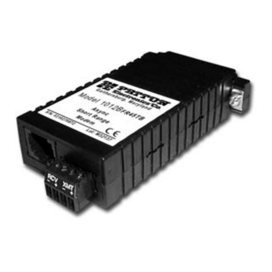
Summary of Contents for Patton electronics 1012B
- Page 1 Part# 07M1012B Doc# 040061U, Rev. B Revised 1/22/08 An ISO-9001 Certified Company USER MANUAL MODEL 1012B Asynchronous Carrier Controlled Short Range Modem SALES OFFICE (301) 975-1000 TECHNICAL SUPPORT (301) 975-1007 http://www.patton.com...
-
Page 2: Radio And Tv Interference
However, there is no guarantee that interference will not occur in a particular installation. If the Model 1012B does cause interference to radio or television reception, which can be determined by disconnecting the... -
Page 3: General Information
The transformers eliminate problems caused by ground loops. With all these features, the 1012B can be used in numerous types of applications. Some of them are simple point-to-point between buildings, multipoint applications, and point-to-point applications which require passing a control signal from end-to-end. - Page 4 By default, the Model 1012B is configured to be a DCE with the transmitter set for controlled carrier. If the 1012B is in controlled carrier mode for multi-point operation, the transmitter is controlled by RTS (pin 4) when it is a DCE, and controlled by CD (pin 8) when configured as a DTE.
- Page 5 1. Using a small screwdriver, insert the tip into one of the slots in the side of the Model 1012B (see Figure 2). Figure 2. Using a small screwdriver to open the Model 1012B case Rotate the screwdriver as shown in Figure 2 to open the case.
- Page 6 RS-232 control signal. When this jumper is removed from the pegs, the 1012B transmitter is constantly on. When the jumper is in place on the pegs, the transmitter is controlled by either RTS or CD. When the control signal is a positive voltage, the transmitter is turned on, if negative voltage, the transmitter is off.
-
Page 7: Installation
4.1.1 TERMINAL BLOCK TWISTED PAIR CONNECTION If your application requires you to connect one or two pair of bare wires to the Model 1012B, you will need to access the external terminal blocks. The following instructions will tell you how to connect the bare wires to the terminal blocks. - Page 8 The Model 1012B is now installed. 4.1.2 MODULAR TWISTED PAIR CONNECTION The Model 1012B offers two interface options for twisted pair connection: RJ-11 (6-wire) jack and RJ-45 (8-wire) jack. Pages 9 and 10 show signal/pin assignments for the jacks, as well as pin-outs for the appropriate twisted pair cable topologies.
- Page 9 Signal/Pin Assignments The 6-wire RJ-11 and 8-wire RJ-45 jack options for the Model 1012B are prewired for a standard TELCO wiring environment. Use the guide below when ordering or constructing twisted pair cables. RJ-11 SIGNAL 1 ..GND†...
-
Page 10: Star Topology
Contact Patton Technical Support (301) 975-1007; http://www.patton.com; or, support@patton.com for specific distance estimates. Table 3 shows how to wire the two-pair cables properly for a Model 1012B star topology. Note that the ground connection is not needed. HOST XMT+ XMT-... -
Page 11: Daisy Chain Topology
DB-25 port of the RS-232 device. After doing so, remember to insert and tighten the two captive connector screws. Note: If you must use a cable to connect the Model 1012B to the RS-232 device, make sure it is a straight through cable of the shortest possible length—we recommend 6 feet (1.8... -
Page 12: Appendix Aspecifications
Transmission Format: Transmission Line: Interfaces: Data Rates: Isolation: Surge Protection: Factory Switch Setting: DCE (transmits from RS-232 on pin 3) Control Signals: RTS/CTS Delay: Connectors: Power Supply: Temperature Range: Altitude: Humidity: Weight: Dimensions: Data Rate 1,200 to 38,400 APPENDIX A SPECIFICATIONS Asynchronous, full duplex, half duplex Two unconditioned twisted pair AWG 19–26... - Page 13 RS-232C PIN CONFIGURATIONS DIRECTION To Model 1012B Data Term. Ready (DTR) - 20 DIRECTION From Model 1012B Data Term. Ready (DTR) - 20 APPENDIX B "DCE" STANDARD SETTING 1- (FG) Frame Ground 2- (TD) Transmit Data 3- (RD) Receive Data...
- Page 14 APPENDIX C MODEL 1012B BLOCK DIAGRAM...
- Page 15 Notes ________________________________________________________ ________________________________________________________ ________________________________________________________ ________________________________________________________ ________________________________________________________ ________________________________________________________ ________________________________________________________ ________________________________________________________ ________________________________________________________ ________________________________________________________ ________________________________________________________ ________________________________________________________ ________________________________________________________ ________________________________________________________ ________________________________________________________ ________________________________________________________ ________________________________________________________ ________________________________________________________ ________________________________________________________ ________________________________________________________ ________________________________________________________ ________________________________________________________ ________________________________________________________...
- Page 16 Dear Valued Customer, Thank you for purchasing Patton Electronics products! We do appreciate your business. I trust that you find this user manual helpful. We manufacture one of the widest selections of data communications products in the world including CSU/DSU's, network termination units, powered and self-powered short range modems, fiber optic modems, interface converters, baluns, electronic data switches, data-line surge protectors, multiplexers, transceivers, hubs, print servers and much more.


Need help?
Do you have a question about the 1012B and is the answer not in the manual?
Questions and answers