Summary of Contents for Patton electronics RS-232
-
Page 1: User Manual
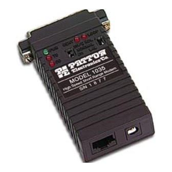
USER MANUAL MODEL 1035 Powered High Speed Short Range Modem RS-232 and V.35 versions SALES OFFICE Part# 07M1035-A (301) 975-1000 Doc# 054071UA Revised 7/6/95 TECHNICAL SUPPORT (301) 975-1007 http://www.patton.com... - Page 2 1035 supports distances to 6 miles over unconditioned twisted pair. The Model 1035 incorporates two V.54 test modes (local analog loop and remote digital loop), which can be activated via the RS-232 or V.35 interface or by a tiny, externally accessible switch. Additionally, a built-in V.52 BER test generator outputs 511 and 511E bit patterns...
-
Page 3: Opening The Case
3.0 CONFIGURATION The Model 1035 provides sixteen configuration switches, which allow selection of data rates, clocking methods, V.54 test modes, RTS/CTS delay and DTE control of test functions. This section describes switch locations and explains all possible switch configurations. 3.1 CONFIGURATION SWITCHES The Model 1035’s unique set of sixteen internal DIP switches allows configuration to an extremely wide range of applications. - Page 4 SWITCH SET SW1 The configuration switches on switch set SW1 set analog loopback, digital loopback and V.54 enable/disable. The default settings are summarized in Figure 3 (below). SW1 SUMMARY TABLE Position Function SW1-1 DTE Control of Analog Loopback SW1-2 DTE Control of Digital Loopback SW1-3 Not Used SW1-4...
-
Page 5: Installation
Once the Model 1035 is properly configured, it is ready to connect to your system. This section tells you how to properly connect the Model 1035 to the twisted pair, RS-232 and V.35 interfaces. 4.1 CONNECTION TO THE TWISTED PAIR INTERFACE The Model 1035 supports communication between two RS-232 devices or two V.35 devices at distances to 6 miles and data rates to 64... -
Page 6: Connection To A "Dte" Device
DTE such as a terminal, PC or host. A direct connection to the RS-232 or V.35 DTE port is most desirable. If you must use a cable to connect the Model 1035 to the DTE port, make sure it is a straight through cable of the shortest possible length—we recommend 6 feet or... -
Page 7: Operation
5.0 OPERATION Once the Model 1035 is properly configured and installed, it should operate transparently—as if it were a standard cable connection. Section 5.0 describes reading the LED status monitors, powering-up and using the built-in V.52 and V.54 test modes. The Model 1035 is powered by a 7.5V DC external wall mount transformer. - Page 8 Unconditioned twisted pair 19 - 26 Clocking: Internal, external or receive loopback Distance: To 6 miles Interfaces: EIA RS-232, CCITT V.24, CCITT V.35 Data Rates: 32, 56 and 64 Kbps (switch selectable) Isolation: Minimum 1500 V RMS via isolation transformers...
-
Page 9: Pin Configurations
APPENDIX B PIN CONFIGURATIONS DIRECTION RS-232 PIN-OUT REFERENCE (DB-25) 1 - (FG) Frame Ground 2 - (TD) Transmit Data From Model 1035 Transmit Clock - 15 3 - (RD) Receive Data 4 - (RTS) Request to Send From Model 1035...


Need help?
Do you have a question about the RS-232 and is the answer not in the manual?
Questions and answers