Advertisement
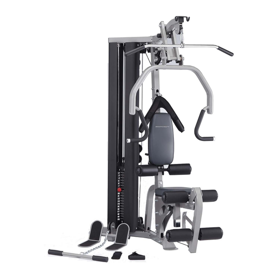
GL/GLX STRENGTH TRAINING SYSTEM
Serial Number Location
S E R I A L
1 2 3 4 5 6 7 8
Record your Serial number
and purchase date here:
S/N __________________
DATE:________________
DEALER:______________
______________________
Model No. BCG-GL
BODYCRAFT is a division
of Recreation Supply, Inc.
OWNERS MANUAL
Recreation Supply Inc.
7699 Green Meadows Drive
Lewis Center, OH 43035
Advertisement
Table of Contents

Related Manuals for BodyCraft GL


Summary of Contents for BodyCraft GL
-
Page 1: Owners Manual
GL/GLX STRENGTH TRAINING SYSTEM OWNERS MANUAL Serial Number Location S E R I A L 1 2 3 4 5 6 7 8 Record your Serial number and purchase date here: S/N __________________ DATE:________________ DEALER:______________ ______________________ Model No. BCG-GL Recreation Supply Inc. - Page 2 8. Make certain all cables are seated within the pulleys before every use. 9. Exercise with care to avoid injury. 10. If you are unsure about the proper use of the BODYCRAFT GL/GLX strength training system call your local BODYCRAFT dealer or our customer service department.
-
Page 3: Recommended Tools
Gym Placement Planner The dimensions below below are based on installing the gym into a corner of your workout room. GL/GLX w/Leg Press GL/GLX Dimensions Option Dimensions GL 45" HEIGHT GL 65" HEIGHT GLX 74" GLX 54" 83" 83" 77"... - Page 4 GL/GLX Assembly Parts List 1 NOTE: IF YOU SEEM TO BE MISSING A PART, DO NOT WORRY, IT LIKELY HAS BEEN PRE-INSTALLED FOR QUALITY CONTROL PURPOSES. (6) PRESS (2) TOP FRAME (1) BASE FRAME (9) LEG (8) SEAT (7) SEAT...
- Page 5 GL/GLX Assembly Parts List 2 NOTE: IF YOU SEEM TO BE MISSING A PART, DO NOT WORRY, IT LIKELY HAS BEEN PRE-INSTALLED FOR QUALITY CONTROL PURPOSES. (40) (37) (41) CLIP (38) CHAIN (36) AB SINGLE ANKLE (4 PCS) CRUNCH HANDLE...
- Page 6 GLX Hardware Parts List NOTE: IF YOU SEEM TO BE MISSING A PART, DO NOT WORRY, IT LIKELY HAS BEEN PRE-INSTALLED FOR QUALITY CONTROL PURPOSES. NO. DESCRIPTION QTY. 5/8" X 5-1/2" HEX HEAD BOLT 3/8" X 4-1/4" HEX HEAD BOLT 3/8"...
- Page 7 STEP 1 ASSEMBLE BASE FRAME To ease the assembly process, Do not tighten bolts until instructed. 1. Attach FRONT UPRIGHT (3) to BASE FRAME (1), using two 3/8" X 3" HEX HEAD BOLTS (82), four 3/8" WASHERS (100) and two 3/8" NYLA-NUTS (104). 2.
- Page 8 STEP 2 ASSEMBLE PRESS STATION 1. Attach PRESS ARM SUPPORT (12) to the TOP FRAME (2) by aligning the holes and inserting the 5/8" X 5-1/2" HEX HEAD BOLT (78) with two 5/8" WASHERS (99) and one 5/8" NTLA-NUT (103). Tighten. 2.
- Page 9 STEP 3 ASSEMBLE SEAT SUPPORT FRAME AND SEAT & BACK PAD 1. Attach SEAT SUPPORT FRAME (8) to FRONT UPRIGHT (3), using three 3/8" X 3" HEX HEAD BOLTS (82) six 3/8" WASHERS (100) and three 3/8" NYLA-NUTS (104). Tighten. 2.
- Page 10 STEP 3 ASSEMBLE SEAT SUPPORT FRAME AND SEAT & BACK PAD 1" 2" 3" 4" 5" 6" (inch)
-
Page 11: Assemble Weight Stack
STEP 4 ASSEMBLE WEIGHT STACK 1. Insert two 1" ID PLASTIC GUIDE ROD HOLDERS (62) into the holes on the BASE FRAME (1). Insert the GUIDE RODS (5) into the 1" ID PLASTIC GUIDE ROD HOLDERS (62). See Note below before proceeding! Slide the LONGER STACK SPACERS (19) onto the GUIDE RODS (5), followed by the RUBBER CUSHIONS (67). - Page 12 STEP 5 INSTALL TOP CABLE Pulleys T3 and T5 are mounted to either side of the steel tab. Do not mount both pulleys to one side. Assemble cables and pulleys simultaneously 1. See Fig. T1 Run the threaded end of the TOP CABLE (74) over pulley T1 at the front of the TOP FRAME (2) and secure using one 3/8"...
- Page 13 STEP 5 INSTALL TOP CABLE TOP CABLE (74) Threaded End Ball End Fig. T1 Fig. T2,T4 STEP1 STEP2 Fig. T6 Fig. T3,T5 Fig. T7 Fig. T8 Fig. T10 Fig. T12 Fig. T9,T11...
- Page 14 STEP 6 INSTALL AB CRUNCH CABLE NOTE: IF YOU HAVE PURCHASED THE GLX/CABLE ARM OPTION, SKIP STEP 6 AND REFER TO THE CABLE ARM ASSEMBLY MANUAL. WHEN FINISHED WITH THE CABLE ARM INSTALLATION, RESUME WITH STEP 7 ON THE NEXT PAGE. DISCARD CABLE 75, YOU WILL USE CABLE #420 IN PLACE OF CABLE #75 LOCATED IN THE CABLE ARM PACKAGE).
- Page 15 STEP 7 INSTALL LOWER CABLE 1. See Fig. L1 Route the steel ball end of the LOWER CABLE (76) under Pulley L1 mounted at the front of the Low Pull Station using one 3/8" X 1-3/4" HEX HEAD BOLT (84) and one 3/8" NYLA-NUT (104). 2.
-
Page 16: Step 8 Install Accessories
STEP 8 INSTALL ACCESSORIES 1. Attach Lat Bar (28), Curl Bar (29), AB Crunch Strap (36) to the GL Strength Training System. - Page 17 COMPLETE PARTS CHART NO. DESCRIPTION QTY. BASE FRAME TOP FRAME FRONT UPRIGHT REAR UPRIGHT GUIDE ROD PRESS ARM SEAT ADJ. FRAME SEAT SUPPORT FRAME LEG EXTENSION ARM UPRIGHT SUPPORT FRAME SEAT BACK ADJUSTER PRESS ARM SUPPORT ADJUSTABLE PULLEY BLOCK DOUBLE PULLEY BLOCK FLOATING PULLEY BLOCK LEG HOLDER STABILIZING PLATE...
- Page 18 COMPLETE PARTS CHART NO. DESCRIPTION QTY. SEAT PAD BACK PAD 90mm PULLEY (3-1/2") 1" T SHAPE END PLUG 2" X 3" END CAP 2" X 2" SQUARE END CAP 1" X 2" END CAP 40 X 80mm OVAL PLUG 1-1/4" ROUND END PLUG PLASTIC COVER PLASTIC ROLLER CAP 1"...
-
Page 19: Exploded View
EXPLODED VIEW 52 84 69 97 13 84 60 92 52 84 101 102 60 92... - Page 20 The Cable Adjustment of GL Strength Training System a. The Cables should be tightened to the point just before the Top Plate lifts off the stack. In other words, if the Top Plate is not resting on the stack, you will need to add length, or, if there is slack in the cables, you will need to shorten the cables.
-
Page 21: Maintenance
5. Clean and apply silicone to the Guide Rods every 6 months. Enjoy many years of a Fit Lifestyle. Thank you for purchasing the BodyCraft GL/GLX Strength Training System. If you have any questions, please call your local BodyCraft dealer, call our customer service department at 800-990-5556 or at www.bodycraft.com.
Need help?
Do you have a question about the GL and is the answer not in the manual?
Questions and answers