Table of Contents

Related Manuals for Super Circuits 940-GSM6


Summary of Contents for Super Circuits 940-GSM6
- Page 1 940-GSM6 940 nm IR GSM Field Surveillance Camera User Manual Please read this manual before using your camera, and always follow the instructions for safety and proper use. Save this manual for future reference. 940-GSM6_CM 6/22/15...
- Page 2 Operate this device only in environments where the temperature or humidity is within the recommended range. Operation in extreme temperatures or humidity levels may cause electric shock and shorten the life of the product. CAUTION LEGAL NOTICE Supercircuits products are designed to meet safety and performance standards with the use of specific Supercircuits authorized accessories.
-
Page 3: Table Of Contents
Table of Contents SECTION 1 Features . . . . . . . . . . . . . . . . . . . . . . . . . . . . . . . . . . . . . . . . . . . . . . . . . . . . . . . . . . . . . . . . . . . . . . . . . . . 1 1.1 Function of the PIR sensors and image capture . - Page 4 NOTES www.supercircuits.com...
-
Page 5: Features
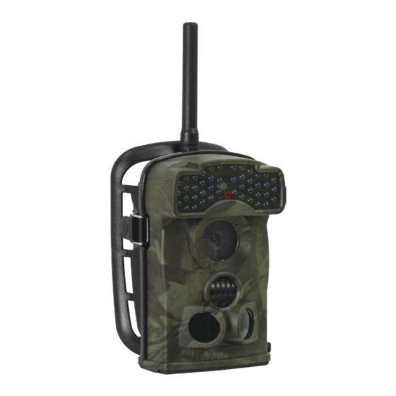
SECTION 1 Features The 940-GSM6 Field Surveillance Camera is a rugged, water-repellent outdoor camera for use in extreme temperature conditions. It includes the MMS (Multimedia Messaging Service) module for transmitting video and pictures to a phone or email address. With its highly sensitive passive infra-red (PIR) sensors, the camera detects the sudden change of ambient temperature caused by moving objects in a region of interest (ROI), triggers to take pictures/videos, and sends the images via a GSM network to the user’s cell... -
Page 6: Function Of The Pir Sensors And Image Capture
SECTION 1: FEATURES 1.1 Function of the PIR sensors and image capture The device includes both side prep infra-red (PIR) sensors, to detect a heat generating object nearing the cameras region of interest (ROI), and a main PIR sensor to detect motion in the ROI, where a photo or video can taken. This combination of the two side prep sensors and the main sensor provides a 100°... -
Page 7: Camera And Mms Module
1.4 Camera and MMS module The 940-GSM6 Field Surveillance Camera includes two modules: a camera module and an MMS module. These modules are usually latched together. To separate them, loosen the captive thumb screw on the back of the unit, undo the buckle on the side, then carefully remove the tab of the camera module from the slot on the side of the MMS module. -
Page 8: Camera Module Features
SECTION 1: FEATURES 1.5 Camera module features The camera module features a built-in infra-red (IR) array for taking photos up to 30’ away in dark environments, and built-in passive IR (PIR) sensors for detecting objects moving into the region of interest (ROI). IR Array Flash Light Sensor... - Page 9 SECTION 1: FEATURES The camera external interface connectors are located Inside the cover on the bottom of the camera module. To open the bottom cover, turn the latch on the lower corner so it points toward the body of the camera, then push it down to open the cover. Latch Latch Alignment...
-
Page 10: Camera Module Controls
SECTION 1: FEATURES 1.5.1 Camera module controls The camera module includes two control components: an ON - OFF - TEST power switch, and a keypad control panel. The switch is accessible when the bottom cover is open. These controls function as follows: Position Function Unit is powered off. -
Page 11: Setup
Setup Setup of the 940-GSM6 includes preparing the Camera module, inserting an SD card and installing batteries, and preparing the MMS module, installing a SIM card (if using MMS) and batteries. After these steps are complete, the Camera module must be configured for the application you are using it for. -
Page 12: Installing Batteries In The Camera Module
SECTION 2: SETUP The camera stores pictures and videos on the SD card in the folder \DCIM\100IMAGE, and all MMS pictures in the folder \DCIM\MMS\100IMAGE with the same filename. Photo filenames are similar to IMAG0001.JPG, and video filenames are similar to IMAG0001.AVI. -
Page 13: Prepare The Mms Module
SECTION 2: SETUP If you are not using the camera for an extended period of time, remove the batteries from the camera to avoid possible acid leak that may damage the camera and void the warranty. CAUTION When battery level gets low, the Motion Indicator in the LED array will flash blue. If using the MMS module with a SIM card, a Battery Low text alert will be sent automatically to the user’s cell phone or email account. -
Page 14: Installing Batteries In The Mms Module
SECTION 2: SETUP SIM Card Card Contacts SIM Card Holder SIM Card Inserted SIM Card Installed 2.2.2 Installing batteries in the MMS module When installing batteries in the battery compartment, follow the (sardine) orientation order shown below. Use four new Energizer® Lithium or better AA batteries for best performance. -
Page 15: Configuration Setup
SECTION 2: SETUP After installing batteries, close the battery compartment cover. When batteries are installed in the MMS module, do not touch the Camera Module Contact Pins with any electrically conductive object. CAUTION 2.3 Configuration setup Configuration setup can be performed by either using the keypad control buttons on the camera module, or using a computer (PC) with the device utility on the media provided. - Page 16 SECTION 2: SETUP Parameter Setting Description 1280 × 720, Select video resolution (pixels per frame). Higher resolution produces better quality videos, but Video Size 640 × 480, creates larger files that use more of the SD card capacity. (affects video clips only) 320 ×...
-
Page 17: Camera Setup With A Pc
SECTION 2: SETUP Parameter Setting Description Value represents the SMS receipt time, “0” indicates 10 minutes, “1 ~ 24” indicates the interval time SMS remote control 0, 1 ~ 24, Off 1 .. 24 hours to receive SMS, Off disables this feature. Press OK and then Enter to revert all camera settings to the manufacturer default values. - Page 18 SECTION 2: SETUP In the camera setup menu, do the following. Refer to the Menu system parameters table above for more information. Select the Mode, Image Size, Video Size, etc. options you prefer from the drop-down menus. Set the Timer, Serial No ., and Time Lapse menu setup as needed. Click the GetTime button to set the camera’s date and time to your computer’s date and time.
-
Page 19: Mms Setup With A Pc
SECTION 2: SETUP Set the camera ON - OFF - TEST power switch to the TEST position. Wait for a message to appear on the LCD display that the camera has been successfully setup. Set the ON - OFF - TEST power switch to OFF. Close the bottom cover and turn the latch to lock the cover closed. - Page 20 SECTION 2: SETUP Open the MMS Mode drop-down list and select either Auto or Manual. Auto: If you selected Auto, open the Country drop-down list and select your country and the Mobile Phone Network Operator (MPNO) for your SIM card. The section below will populate with parameters pertaining to the selected MPNO, including URL, APN, Gateway and Port.
-
Page 21: Smtp Setup With A Pc
SECTION 2: SETUP If you need to setup the SMTP features of the device, skip the following steps in this MMS setup procedure, and go to “2.3.4 Smtp Setup with a PC” on page 17. Eject the USB device (your SD card) from the Windows operating system, then disconnect your camera USB cable from the computer and camera. - Page 22 SECTION 2: SETUP Select the Smtp Mode: In Auto mode, select the Country and Operator. — In Manual mode, enter an APN, Account and Password. These parameters should be provided by your mobile — operator. In the Sender frame, enter your Email server, port, sender Email and Password. In the Recipients frame, enter, and the recipient’s email address.
-
Page 23: Mount And Activate The Camera
SECTION 2: SETUP Click Generate. A file will be written to the root directory of your SD card. Eject the USB device (your SD card) from the Windows operating system, then disconnect your camera USB cable from the computer and camera. Click Exit to close the setup utility. -
Page 24: Using Your Camera
SECTION 3: USING THE CAMERA SECTION 3 Using your camera 3.1 ON mode Set the power switch to the ON position to enter the normal operating mode. The Motion Indicator will flash red for about 10 seconds and the camera starts working as programmed without any manual handling. If the camera is setup to record on motion detection, it will wait in standby (low power) mode, and power up to shoot pictures or record videos when objects enter the PIR area of the main sensor as follows: When an object enters the PIR area of the side prep sensors, the prep sensors detect the movement and fully powers up the... -
Page 25: View Local Mnpo Name And Signal Strength
SECTION 3: USING THE CAMERA 3.2.1 View Local MNPO name and signal strength WIth the camera and MMS modules connected and an antenna attached: Using a TV monitor: Open the bottom cover, than attach a video cable between the TV OUT connector on the camera and a composite video input on a TV monitor. -
Page 26: Sms Remote Control
SECTION 3: USING THE CAMERA Set the power switch on the camera to OFF. Reattach the MMS module to the camera module. If a code, instead of MPNO information, appears on the screen, an exception condition occurred: - SIM: No SIM card or installed incorrectly. - CSQ: No signals. -
Page 27: Important Notes
SECTION 3: USING THE CAMERA Order code Function code Example Meaning Email Maximum 48 characters 14*info@ ltlacorn.com# Email: info@ltlacorn.com Maximum photo number setting. 0: no limit 15*0# No limit Time lapse - 0: Off, 1: Time indicated with 2 bytes. Example - 1 hour, 16*1013302# 1 hour, 33 minutes, 2 seconds 33 minutes, 2 seconds is indicated by 013302. -
Page 28: Auto Adjustment Of Video Length
SECTION 3: USING THE CAMERA 3.3.2 Auto adjustment of video length When battery power gets low, this camera automatically shortens the video length to take more video clips of surveillance targets, which can provide more useful information. To extend the battery life, we suggest that you install 8 AA alkaline batteries when using the camera in Video mode or Cam+Video mode. -
Page 29: Specifications
SECTION 4: SPECIFICATIONS SECTION 4 Specifications Item Specification Image sensor 5 Mega Pixels Color CMOS Maximum pixel size 2560 x 1920 Lens FOV = 52°; auto IR-cut IR Flash 30 ft (9.14 m) LCD screen 2.36” (48 x 35.69 mm); 480 (RGB)*234 dots; 16.7 M colors Keypad 6 keys Memory... - Page 30 SECTION 4: SPECIFICATIONS Item Specification Power supply 1 x 4 or 2 x 4 AA batteries External DC power adapter Plug Size: 4.0 x 1.7; Voltage: 6 ~ 12 Vdc (1 ~ 2 A) Standby current 0.4 mA Standby time 3 ~ 6 months (with 4 or 8 x AA batteries) Auto power off Auto power off after 2 minutes of no keypad input...
-
Page 31: Appendix Amms Troubleshooting
APPENDIX A: MMS TROUBLESHOOTING APPENDIX A MMS Troubleshooting Following are some common MMS problems and suggested solutions. I set up a new receiving phone number, but MMS pictures are still being sent to the old number. What should I do? Switch the camera OFF.
Need help?
Do you have a question about the 940-GSM6 and is the answer not in the manual?
Questions and answers