Table of Contents
Advertisement
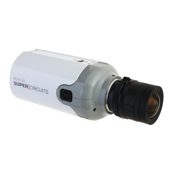
Color CCD Box Camera
User Manual
Products:
Please read this manual before installing and using this camera and always follow instructions for proper use.
PC33C5G, PC33C5G-RTI, PC33C5G-RTIA,
PC153C5G, PC153C5G-RTI, PC153C5G-RTIA
Camera With Optional Lens
Save this manual away for future reference.
PC33C5G_PC153C5G_CM
5/12/11
Advertisement
Table of Contents

Related Manuals for Super Circuits PC33C5G


Summary of Contents for Super Circuits PC33C5G
-
Page 1: User Manual
Color CCD Box Camera User Manual Products: PC33C5G, PC33C5G-RTI, PC33C5G-RTIA, PC153C5G, PC153C5G-RTI, PC153C5G-RTIA Camera With Optional Lens Please read this manual before installing and using this camera and always follow instructions for proper use. Save this manual away for future reference. - Page 2 LEGAL NOTICE Supercircuits products are designed to meet safety and performance standards with the use of specific Supercircuits authorized accessories. Supercircuits disclaims liability associated with the use of non-Supercircuits authorized accessories. The recording, transmission, or broadcast of any person’s voice without their consent or a court order is strictly prohibited by law.
- Page 3 PRECAUTIONS Precautions Do not install the camera in temperature condition or humidity that is • outside the specified operating range. Do not install the camera under unstable lighting. • Do not touch the CCD element. If it is necessary to clean the element, use •...
-
Page 4: Table Of Contents
TABLE OF CONTENTS Table of Contents SECTION 1 Features ..........1 1.1 Camera components . -
Page 5: Section 1 Features
SECTION 1: FEATURES Features SECTION 1 1/3” Sony® CCD image sensor • C/CS lens mount (lens not included) • Digital Noise Reduction (DNR) • Digital Wide Dynamic Range (D-WDR) • Motion detection (4 zones) • Auto white balance • True Day & Night function •... -
Page 6: Camera Components
SECTION 1: FEATURES 1.1 Camera components Front View Light sensor Microphone Indicator LED Back View Audio Function setup joystick UTP Gain Power (12 VDC or 24 VAC) Video RS485 and UTP terminations www.supercircuits.com... - Page 7 SECTION 1: FEATURES Side View Auto-Iris Jack Auto-Iris Jack Pin Assignments DC Driver - Control + Control - Drive + Drive Color Box Camera User Manual...
-
Page 8: System Options
SECTION 1: FEATURES 1.2 System options The camera can be connected to a CCTV monitor or to a DVR. Connect Multiple camera system with DVR and monitor Multiple camera system with DVR and monitor www.supercircuits.com... -
Page 9: Section 2 Installation
Hex wrench • 2.2 What you need To install the camera, you will need: C/CS type lens (PC33C5G and PC153C5G) • Mounting bracket, such as a Supercircuits SKU MB14 • Hardware and tools to attach the mounting bracket to the mounting surface •... - Page 10 SECTION 2: INSTALLATION mounting bracket, this procedure can serve as a general guideline for installing your equipment. 1. Using the bracket mounting plate as a template, mark the location of the mounting screw holes on the mounting surface. Camera attachment Mounting screw screw locations...
- Page 11 SECTION 2: INSTALLATION 6. Loosen the directional adjustment screw so that the camera adjustment screw moves freely. 7. Attach the camera to the mounting bracket by tightening the camera attachment screw into the mounting bracket connector. 8. Tighten the directional adjustment screw to hold the camera in position. 9.
-
Page 12: Aiming The Camera
SECTION 2: INSTALLATION 11. Attach the power extension cable to a 12 VDC adapter or power source and power on the camera. 12. Verify that video from the camera can be seen on the monitor. 2.4 Aiming the Camera 1. While observing video from the camera, hold the camera in place and loosen the directional adjustment screw until the camera can move freely. -
Page 13: Section 3 Setup Menu (Osd) Usage
SECTION 3: SETUP MENU USAGE SETUP Menu (OSD) Usage SECTION 3 The SETUP menu can be accessed and configured using the function setup joystick on the back of the camera, or through an RS-485 interface. It appears as an OSD over the video image from the camera. -
Page 14: Setup Menu Options
SECTION 3: SETUP MENU USAGE To access the SETUP menu: 1. Connect a video monitor to the video connector on the back of the camera. 2. While observing video from the camera, press the joystick in (toward the camera backplate) to open the SETUP menu. 3. - Page 15 SECTION 3: SETUP MENU USAGE Manual: Select for manual lenses. • EXPOSURE SHUTTER: Select either auto or manual shutter. • AUTO: Select for auto shutter. Default: 1/60 sec — FLK: Select for Flicker shutter. Select from 1/250 ~ 1/100000 sec shutter time. —...
- Page 16 SECTION 3: SETUP MENU USAGE AWC g SET: To find the optimal setting for the current luminance environment in • this mode, point the camera towards a sheet of white paper then press SET. NOTE When the environment changes, repeat this procedure. MANUAL: Select this mode to manually set the white balance.
- Page 17 SECTION 3: SETUP MENU USAGE BACKLIGHT OFF: Deactivate the BACKLIGHT Function. • BLC: Enable to select an area of a picture to view more clearly. • AREA SEL: AREA 1 / AREA 2 — AREA STATE: ON /OFF — GAIN: Adjust the value between. Range: 0 ~ 255 steps —...
- Page 18 SECTION 3: SETUP MENU USAGE DAY / NIGHT AUTO: This mode is set for color in a normal environment, but switches to B / W • mode when ambient illumination is low. To set up the switching time or speed for AUTO mode.
- Page 19 SECTION 3: SETUP MENU USAGE DPC (Dead pixel compensation). To set the DPC, cover the lens, then select DPC and • press SET. SPECIAL • CAM TITLE: If you enter a title, the title will appear on the image. — OFF: No title will be displayed on the monitor.
- Page 20 SECTION 3: SETUP MENU USAGE MOTION: If you connect an alarm device to the camera, you can monitor activities • more efficiently because a signal is generated by the camera whenever a motion is detected. The motion detection signal is output through the MD OUT port. OFF: Deactivate the MOTION function.
- Page 21 SECTION 3: SETUP MENU USAGE LT: 0 ~ 194 — RT: 0 ~ 194 — LB: 0 ~ 194 — RB: 0 ~ 194 — F: 0 ~ 80 — N: 0 ~ 80 — T: 2 ~ 15 — IMAGE ADJ: •...
- Page 22 COMM ADJ (communication adjustment): Use function to set up the communication • status between the camera and an external controller. NOTE: PC33C5G and PC153C5G cameras do not support PTZ. CAM ID: Set the camera ID number. Range: 0 ~ 255 —...
-
Page 23: Section 4 Cleaning
SECTION 4: CLEANING Cleaning SECTION 4 Clean the camera lens and IR lamp shield with an approved glass cleaning solution and a lint free cloth. Remove all foreign particles, such as plastic or rubber materials, attached to the • camera housing. These may cause damage to the surface over time. Dust can be removed from the unit by wiping it with a soft damp cloth. -
Page 24: Section 5 Specifications
SECTION 5: SPECIFICATIONS Specifications SECTION 5 Model PC33C5G PC153C5G Image Sensor 1/3” Sony CCD Total Pixels 811(H) x 504(V) 537(H) x 505(V) Effective Pixels 768(H) x 494(V) 510(H) x 492(V) Resolution Color: 600 TV Line B/W: 700 TV Line Color: 450 TV Line B/W: 500 TV Line... - Page 25 SECTION 5: SPECIFICATIONS Model PC33C5G PC153C5G Operating Temperature 14°F ~ 113°F (-10°C ~ 45°C) Storage Temperature 44°F ~ 140°F (-20°C ~ 60°C) Dimensions (L x W x H) 4.43” x 2.04” x 2.38” (112.5mm x 60.33mm x 51.93mm) Weight 7.05 oz ± 0.35 oz (200 g ± 10 g), camera body...
-
Page 26: Appendix A Troubleshooting
APPENDIX A: TROUBLESHOOTING Troubleshooting APPENDIX A Before sending the camera for repair, please follow the suggestions listed below and make sure that the camera is installed correctly. If it still does not perform adequately, please consult your supplier or contact Technical Support at 1.800.335.9777. 1. - Page 27 APPENDIX A: TROUBLESHOOTING c. The video cables are not connected properly. This camera is a precision instrument and when treated with care, will provide years of satisfactory performance. If a problem does occur, do not open the camera to make repairs. Servicing should always be referred to CAUTION your supplier.
-
Page 28: Appendix B Dimensions
APPENDIX B: DIMENSIONS Dimensions APPENDIX B For cameras: PC33C5G_CM and PC153C5G 4.43” 2.38” 2.04” www.supercircuits.com...
Need help?
Do you have a question about the PC33C5G and is the answer not in the manual?
Questions and answers