
Related Manuals for Kaco Powador 30.0 TL3 M/XL


Summary of Contents for Kaco Powador 30.0 TL3 M/XL
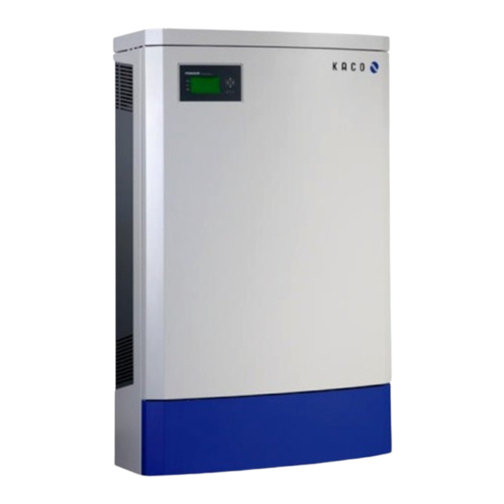
- Page 1 Powador 30.0 TL3 M/XL 33.0 TL3 M/XL 36.0 TL3 M/XL 39.0 TL3 M/XL Operating Instructions English translation of German original...
-
Page 3: Table Of Contents
Operating Instructions for Installers and Operators Powador 30.0 TL3 M/XL 33.0 TL3 M/XL 36.0 TL3 M/XL 39.0 TL3 M/XL Contents General Notes ..........4 Confi guration and Operation....31 About this documentation .........4 Controls ..............31 Layout of Instructions ...........4 Starting up for the fi rst time ......34 Safety ............ -
Page 4: General Notes
G ener al N o te s General Notes About this documentation WARNING Improper handling of the inverter can be hazardous › You must read and understand the operating instructions before you can install and use the inverter safely. 1.1.1 Other applicable documents During installation, observe all assembly and installation instructions for components and other parts of the system. - Page 5 G ener al N o te s 1.2.3 Additional information symbols NOTE Useful information and notes Country-specifi c function Functions restricted to one or more countries are labelled with country codes in accordance with ISO 3166-1. 1.2.4 Instructions symbols guide a) Single step instructions or instructions that can be carried out in any sequence: Instructions ↻...
-
Page 6: Safety
S af ety Safety DANGER Lethal voltages are still present in the terminals and cables of the inverter even after the inverter has been switched off and disconnected. Severe injuries or death will occur if the cables and terminals in the inverter are touched. Only authorised electricians who are approved by the supply grid operator may open, install or maintain the inverter. -
Page 7: Protection Features
NOTE The EU declaration of conformity can be found in the appendix. For information on grid coupling, grid protection and safety parameters along with more detailed instructions see our web site at http://www.kaco-newenergy.de/. Operating Instructions Powador 30.0-39.0 TL3_EN Page 7... -
Page 8: Description
D escri p ti o n Description Mode of Operation The inverter converts the DC voltage generated by the PV modules into AC voltage and feeds it into the grid. The feed-in process begins when there is suffi cient sunlight and a specifi c minimum voltage is present in the inverter. If, as it gets dark, the voltage drops below the minimum voltage value, feed-in operation ends and the inverter switches off . - Page 9 D escri p ti o n 3.2.1.2 Summary of the components PV generator The PV generator, i.e. the PV modules, converts the radiant energy of sunlight into electrical energy. DC terminal point Options for parallel connections of several generator strings: •...
- Page 10 100 kW. The power reduction is achieved using a ripple control receiver in KACO new energy GmbH inverters. If necessary, the power supply company can reduce the power of the system remotely using an additional device from the Powador proLOG family.
- Page 11 D escri p ti o n Country-specifi c function MSp. 3.2.3.4 Frequency-dependent power reduction Frequency-dependent power reduction in accordance with the BDEW Medium Voltage Directive (“Mittelspannungsrichtlinie”) is activated for units that are operated with Germany as the country setting and medium voltage as the grid type. Data relating to power reduction: Start of power reduction 50.2 Hz...
- Page 12 KACO recommends the Tera Term terminal program This program, off ered as freeware, is able to export the results of the shutdown test to a text fi le. This text fi le can then be used to create a PDF fi le with a date and time stamp.
- Page 13 To connect the RS485 interface, contact your authorised electrician. For monitoring your PV system using the RS485 interface, KACO new energy GmbH off ers the following units: Powador-proLOG S to XL (optional) Powador-proLOG allows you to monitor up to 31 inverters simultaneously.
-
Page 14: Technical Data
T echni ca l Dat a Technical Data Electrical Data Input levels 30.0 TL3 33.0 TL3 36.0 TL3 39.0 TL3 30 000 33 000 36 000 39 000 Max. PV generator power [W] DC MPP range from [V] to [V] 350 to 800 Operating range from [V] to [V] 200 to 800*... -
Page 15: Mechanical Data
T echni ca l Dat a Mechanical data 30.0 TL3 / 33.0 TL3 / 36.0 TL3 / 39.0 TL3 Display Graphical LCD, 3 LEDs Controls 4-way button, 2 buttons Interfaces Ethernet, USB, RS485, S0 Fault signal relay Potential-free NO contact, max. 30 V DC/1A or 230 V AC/1 A AC connection terminals Screw terminals inside the unit min. -
Page 16: Transportation And Delivery
T r a nspo rta ti o n an d De li ve ry Transportation and Delivery Delivery Every inverter leaves our factory in proper electrical and mechanical condition. Special packaging ensures that the units are transported safely. The shipping company is responsible for any transport damage that occurs. 5.1.1 Scope of delivery •... -
Page 17: Mounting The Inverter
Take care to ensure suffi cient ventilation of the inverter. › Immediately remove dirt, especially on vents. › Failure to observe these warnings may lead to inverter damage which is not covered by the KACO new energy GmbH manufacturer warranty. Operating Instructions Powador 30.0-39.0 TL3_EN Page 17... - Page 18 M o unti ng th e Inve rt e r Authorised electrician NOTE Power reduction due to heat accumulation. If the recommended minimum clearances are not observed, the inverter can go into power regulation mode or protective shutdown due to insuffi cient ventilation and the resulting heat buildup.
-
Page 19: Installing And Securing The Inverter
M o unti ng th e Inve rt e r Authorised electrician 1328 766.5 Figure 7: Drill hole clearances (in mm) Installing and securing the inverter Drilling the holes Mark drill holes (4x) on bottom. 2. For wall mounting: Draw position of drill holes on wall (2x). Drill the holes. -
Page 20: Installing The Inverter
I n sta l li ng the Inve rt e r Authorised electrician Installing the hood ↻ Remove the EMC sheet metal. Place the hood on the top side of the housing. 2. Secure the hood to the inverter housing from the inside using the enclosed fastening screws. »... -
Page 21: Making The Electrical Connection
I n sta l li ng the Inve rt e r Authorised electrician Making the electrical connection Make the connection to the PV generator as well as the grid connection via the PCB terminals in the connection area of the inverter. Note the following conductor cross-sections: AC connection DC connection DC connection (XL) - Page 22 For cable lengths up to 20 m, use the conductor cross-sections named in table 6. Longer cable lengths require larger conductor cross-sections. Model Conductor cross- Fuse protection: gL safety fuses section Powador 30.0 TL3 M/XL 16.0 mm² 63 A for 16.0 mm² conductor cross-section Powador 33.0 TL3 M/XL 16.0 mm² 63 A for 16.0 mm² conductor cross-section Powador 36.0 TL3 M/XL...
- Page 23 I n sta l li ng the Inve rt e r Authorised electrician 7.2.2 Connecting the PV generator Connect the PV generator on the right of the connection area (see Figure 8 on page 21). Use the provided cable fi ttings. DANGER Risk of fatal injury due to contact voltages.
- Page 24 I n sta l li ng the Inve rt e r Authorised electrician Insert string fuses Open fuse holder. 2. Remove and store short-circuit bridges. Insert suitable string fuses into the DC positive fuse holders. 4. Close the fuse holders. »...
- Page 25 I n sta l li ng the Inve rt e r Authorised electrician MPP-Tracker A MPP-Tracker B MPP-Tracker C Eingang Eingang Eingang 9 10 11 12 Figure 10: Recommended standard connection for Powador 39.0 TL3 XL 7.2.2.4 Connecting the PV generator DANGER Risk of fatal injury due to electric shock Severe injury or death will result if the live connections are touched.
-
Page 26: Connecting The Interfaces
I n sta l li ng the Inve rt e r Authorised electrician Connecting the interfaces All interfaces are located on the connection circuit board in the upper area of the inverter door. Use the provide cable fi ttings and connect the connection cables to the circuit board. DANGER Risk of fatal injury due to electric shock Severe injury or death from improper use of the interface connections and non-observance of... - Page 27 I n sta l li ng the Inve rt e r Authorised electrician 7.3.3 Connecting the Ethernet interface NOTE The connection plug of an RJ45 cable is larger than the opening of an M25 cable fi tting when it is installed.
- Page 28 I n sta l li ng the Inve rt e r Authorised electrician NOTE Diff erent manufacturers do not always interpret the standard on which the RS485 protocol is based in the same way. Note that the wire designations (DATA- and DATA+) for wires A and B may vary from one manufacturer to another.
- Page 29 Connecting "Inverter off " digital input (optional) NOTE The Powador-protect digital output can only be used with suitable KACO inverters. When using devices from other manufacturers or in combination with KACO inverters, bus coupler circuit- breakers as a minimum must be used for shutting down devices from other manufacturers.
-
Page 30: Sealing The Connection Area
I n sta l li ng the Inve rt e r Authorised electrician Sealing the connection area The requirements of protection rating IP54 are met by closing the unused cable fi ttings with blind caps. 2. Put on the lid for the connection area. Close and lock the housing door. -
Page 31: Confi Guration And Operation
You can hear the grid relay switch on. * The waiting period ensures that the generator voltage continuously remains above the power delivery limit of 200 V. For country-specifi c waiting periods see out web site at http://www.kaco-newenergy.de/. Operating Instructions Powador 30.0-39.0 TL3_EN Page 31... - Page 32 C onfig ura tion an d O pe rat i on Operating status LEDs Display Description Feed-in operation Power fed into the grid The green “Operating” LED is illuminated. or measured values The green “Feed-in” LED is illuminated. The “Feed-in” icon appears on the desktop.
-
Page 33: Control Buttons
C onfig ura tion an d O pe rat i on 8.1.3 Control buttons The inverter is operated using the 4-way button and the OK and ESC buttons. 8.1.3.1 Desktop Opening the menu ↻ The inverter is operating. ↻ The LCD is showing the desktop. ... -
Page 34: Starting Up For The Fi Rst Time
C onfig ura tion an d O pe rat i on Starting up for the fi rst time When started for the fi rst time, the inverter displays the confi guration assistant. It takes you through the settings necessary for the initial start-up. NOTE After confi guration is completed, the confi guration assistant does not appear again when the inverter is restarted. - Page 35 C onfig ura tion an d O pe rat i on 8.3.2 Menu structure Icons used: Menu level (0, 1, 2, 3) Submenu available Display menu Country-specifi c setting MSp. Option menu Country and grid type-specifi c setting Password-protected menu Country- Menu Display/...
- Page 36 C onfig ura tion an d O pe rat i on Country- Menu Display/ Action in this menu/meaning spec. setting level setting Displays the recorded operating data graphically. Select the measured value to be displayed. Supported measured values: • Grid power P(grid) •...
- Page 37 C onfig ura tion an d O pe rat i on Country- Menu Display/ Action in this menu/meaning spec. setting level setting Releases the use of the fault signal relay for internal consumption control of the Powador-priwatt. Enter the password. Activate priwatt 2.
- Page 38 2. Confi rm the entry with the OK button. Country Set the desired country setting. NOTE: This option infl uences the country-specifi c operating settings of the inverter. Please consult KACO service for further information. Select the grid type for the inverter’s installation Grid type/ guideline location.
- Page 39 C onfig ura tion an d O pe rat i on Country- Menu Display/ Action in this menu/meaning spec. setting level setting Confi gures the support for grid shutdown by a Powador protect connected to the digital input of the inverter. ↻...
- Page 40 C onfig ura tion an d O pe rat i on Country- Menu Display/ Action in this menu/meaning spec. setting level setting The voltage drop between the inverter and the feed-in meter is added to the limit value that was set for grid shutdown according to EN 50160.
- Page 41 C onfig ura tion an d O pe rat i on Country- Menu Display/ Action in this menu/meaning spec. setting level setting Specify the target voltage. MSp. Specify slope. Q(U) characteristic Specify change time. Enables manual execution of the self test. Activ.
-
Page 42: Monitor Inverter
C onfig ura tion an d O pe rat i on Monitor inverter The inverter has an integrated web server. This makes it possible to monitor and record the operating state and yield of your PV system. You can display the recorded data using: •... - Page 43 C onfig ura tion an d O pe rat i on NOTE You can also access the web server of the inverter via the Internet. To do this, additional settings of your network confi guration, particularly your Internet router, are required. Note that communication with the inverter is carried out over an unsecured connection, particularly in the case of a connection over the Internet.
-
Page 44: Performing A Software Update
Do not interrupt the DC and AC power supply during the update process. Preparing for the software update Download the software update fi le from the KACO web site and store it on your hard disk. 2. Extract the update fi le (.ZIP) completely onto the USB stick. -
Page 45: Maintenance/Troubleshooting
M a in tenance/Tro u b le s ho ot in g Maintenance/Troubleshooting Visual inspection Inspect the inverter and the cables for visible damage and pay attention to the operating status display of the inverter. In case of damage, notify your installer. Repairs may only be carried out by authorised electricians. NOTE Have your installer check for proper operation of the inverter at regular intervals. -
Page 46: Faults
B = Action of the operator E = The indicated work may only be carried out by an authorised electrician. K = The indicated work may only be carried out by a service employee of KACO new energy GmbH. Page 46... - Page 47 B = Action of the operator E = The indicated work may only be carried out by an authorised electrician. K = The indicated work may only be carried out by a service employee of KACO new energy GmbH. Operating Instructions Powador 30.0-39.0 TL3_EN...
- Page 48 B = Action of the operator E = The indicated work may only be carried out by an authorised electrician. K = The indicated work may only be carried out by a service employee of KACO new energy GmbH. Page 48...
-
Page 49: Messages On The Display And The "Fault" Led
B = Action of the operator E = The indicated work may only be carried out by an authorised electrician. K = The indicated work may only be carried out by a service employee of KACO new energy GmbH. Status... - Page 50 M a in tenance/Tro u b le s ho ot in g Status Display Explanation Action Notify your Resid. current Residual current was detected. The shutdown feed-in was interrupted. authorised electrician. Notify your Generator There is an insulation fault on the insulation PV generator.
- Page 51 M a in tenance/Tro u b le s ho ot in g Status Display Explanation Action Notify your Line failure: Grid frequency is too high. This fault can be grid-related. authorised Overfrequency electrician. Notify your Line failure: The grid voltage measurement according to EN 50160 has exceeded authorised average voltage...
- Page 52 Notify authorised Buff er 1, buff er 2 The control board is defective. self test error electrician / KACO Service Notify KACO Service Relay 1, relay 2 self The power section is defective. test error Notify authorised Protect. shutdown...
-
Page 53: Service
S er vi ce Service If you need help solving a technical problem with one of our KACO products, please contact our service hotline. Please have the following information ready so that we can help you quickly and effi ciently: •... -
Page 54: Lekapcsolás / Leszerelés
S hutdow n/ Dis ass e m b ly Authorised electrician Shutdown/Disassembly 11.1 Shutting down the inverter DANGER Lethal voltages are still present in the terminals and cables of the inverter even after the inverter has been switched off and disconnected. Severe injuries or death will occur if the cables and terminals in the inverter are touched. -
Page 55: Appendix
A p pend ix Appendix EU Declaration of Conformity Manufacturer’s name KACO new energy GmbH and address Carl-Zeiss-Straße 1 74172 Neckarsulm, Germany Product description Photovoltaic feed-in inverter Type designation 30.0 TL3 M / 33.0 TL3 M / 36.0 TL3 M / 39.0 TL3 M 30.0 TL3 XL / 33.0 TL3 XL / 36.0 TL3 XL / 39.0 TL3 XL... - Page 56 Carl-Zeiss-Straße 1 · 74172 Neckarsulm · Germany · Tel. +49 7132 3818-0 · Fax +49 7132 3818-703 · info@kaco-newenergy.de · www.kaco-newenergy.com...
Need help?
Do you have a question about the Powador 30.0 TL3 M/XL and is the answer not in the manual?
Questions and answers