Table of Contents
Advertisement
Quick Links
Advertisement
Table of Contents

Related Manuals for Paramount Fitness FS-55 Pec Fly/Rear Delt


Summary of Contents for Paramount Fitness FS-55 Pec Fly/Rear Delt
- Page 1 FS-55 SSEMBLY ANUAL AM-FS55...
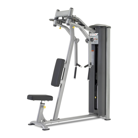
- Page 2 ESSAGE TO USTOMERS Thank you for purchasing the Paramount FS-55 Pec Fly/Rear Delt machine. Because of the many unique features included in this product, this manual was created to provide you with information on how to properly assemble and maintain your equipment. Proper maintenance will ensure that your new equipment will last for years.
-
Page 3: Table Of Contents
ABLE OF ONTENTS ..........................4 AFETY ..................5 ENERAL ARE AND AINTENANCE ....................6 IMENSIONS AND EIGHT ........................7 REPARATION ....................8 ARTON ONTENTS ....................9 ARTON ONTENTS & A NSTALLATION SSEMBLY 1: A ..............10 SSEMBLE THE RAME 2: A .................. -
Page 4: Safety
AFETY 1. Review and understand all of the warning labels affixed to this machine and on the facility safety sign. Replace any warning label at first sign of wear. Labels and the Facility Safety Sign may be obtained from Paramount free of charge. 2. -
Page 5: Eneral Are And
ENERAL ARE AND AINTENANCE 1. Cable Ends: Inspect end fittings daily for wear. Replace cables at the first sign of wear or on an annual basis. If the cable tension has been adjusted, be certain that the cable nut is tight. 2. -
Page 6: Imensions And Eight
IMENSIONS AND EIGHT “I ” M ACHINE IMENSIONS ACHINE EIGHT AND LOOR OADING EIGHT TACK ONFIGURATION ACHINE WEIGHT PPROXIMATE LOOR OADING 170 lbs. 426 LBS [194 KG] 45 LBS/FT [220 KG/M 250 lbs. 506 LBS [230 KG] 53 LBS/FT [261 KG/M Maximum user weight is 300 Lbs. -
Page 7: Reparation
REPARATION EQUIRED OOLS Ratchet Wrench and Socket: 9/16” Wrenches: 9/16”, 3/4” (or an adjustable crescent wrench). Rubber mallet. Allen wrenches: (included with the machine) Weight Plate Cartons Depending upon your order, this machine can be assembled with either a 170 lb. or 250 lb. -
Page 8: Box 1 Carton Contents
ARTON ONTENTS ITEM UMBER ESCRIPTION FS55-UPR-000X FRAME, UPRIGHT FS55-SHD-100X SHROUD, FRONT FS-SHD-250X SHROUD, REAR FS-GRD-200X GUIDE ROD ASSEMBLY FS-BKT-000 GUIDE ROD BRACKET FS-WSB-000 WEIGHT STACK BASE FS-CAP-000X TOP CAP FS-BKT-001 BRACKET, TOP CAP FS55-PAD-000X PAD, BACK FS54-PAD-100X PAD, SEAT... -
Page 9: Box 2 Carton Contents
ARTON ONTENTS ITEM UMBER ESCRIPTION FS55-MFR-300X MAIN FRAME, SUPPORT FS55-SFR-200X SEAT FRAME FS55-MFR-200X MAIN FRAME, BOTTOM FS55-SFR-100X SEAT FRAME, SEAT FS55-AXL-100X AXLE, PIVOT FS55-ARM-400X RIGHT ARM FS55-ARM-100X LEFT ARM FS55-MFR-100X MAIN FRAME, TOP FS55-AXL-200X CAM, RIGHT ARM FS55-AXL-300X CAM, LEFT ARM FS55-PHS-000X FLOATING PULLEY SET FS-SBR-000X... -
Page 10: Main Frame
1: A SSEMBLE THE RAME 1. Assemble frame components as shown. ITEM UMBER ESCRIPTION FS55-UPR-000X UPRIGHT FRAME 2. Tighten all the hardware after the FS55-MFR-300X MAIN FRAME, SUPPORT components have been aligned. FS55-MFR-100X MAIN FRAME, TOP FS55-MFR-200X MAIN FRAME, BOTTOM FS55-SFR-200X SEAT FRAME C 445... - Page 11 1: A SSEMBLE THE RAME 12,7,10,11,9 12,8,11,9 6,10,9 12,13,11,9 12,13,11,9 12,6,10,11,9 X 2 12,6,11,9...
-
Page 12: Arm
2: A SSEMBLE THE 1. Insert the axle from the top of ITEM UMBER ESCRIPTION the main frame and install the FS55-AXL-100X AXLE, PIVOT cam onto the axle. Align the FS55-AXL-300X CAM, LEFT ARM holes on the cam and the axle FS55-AXL-200X CAM, RIGHT ARM and install the spring roll pin. - Page 13 2: A SSEMBLE THE SET SCREW CUP PT 1/4-20, 1/4”...
- Page 14 3: A & B SSEMBLE THE 1. Install the seat pad and back pad as ITEM UMBER ESCRIPTION shown below. FS55-SFR-100X SEAT FRAME, SEAT 2. Tighten all hardware shown below. FS54-PAD-100X PAD, SEAT FS55-PAD-000X PAD, BACK C-446 SCREW, HH, 3/8-16 x 1-1/4” C 749 WASHER, LOCK, 3/8 C 754C...
-
Page 15: Eight Tack
4: A SSEMBLE THE EIGHT TACK 1. Install selector pin and floating pulley ITEM UMBER ESCRIPTION housing as shown. Leave about 1/4 FS55-PHS-000X FLOATING PULLEY SET inch spacing between the bottom of FS-SFR-000X TOP PLATE/SELLECTOR BAR the housing to the top of the nut. Lock FS-SPN-000X SELLECTOR PIN the housing in place with the nut as... -
Page 16: Able
5: I NSTALL THE ABLE 1. Route the cable as shown on page ITEM UMBER ESCRIPTION FS55--UPR-022 PULLEY PROTECTOR 2. Install all the pulleys as shown B 900 PULLEY, 4-1/2” DIA below. Lean the guide rods out to FS55-CBL-100X CABLE install the bolts inside the upright C 448 SCREW, HH, 3/8-16 X 1-3/4”... - Page 17 5: I NSTALL THE ABLE Detail route of the cable Adjust these two stops to keep 2 inch clearance between the handle shown below. 2”...
- Page 18 6: I NSTALL THE RONT HROUD 1. Install the front shroud as shown ITEM UMBER ESCRIPTION below. FS55-SHD-100X SHROUD, FRONT 2. Secure the guide rod by installing the FS-BKT-000 GUIDE ROD BRACKET guide rod brackets. C 445 SCREW, HH 3/8-16, 1” C 754C WASHER, FLAT, 3/8 3.
- Page 19 7: I & T NSTALL THE HROUD 1. Assemble the rear shroud as ITEM UMBER ESCRIPTION shown. FS-SHD-250X SHROUD, REAR 2. Operate the machine and make FS-CAP-000X TOP CAP sure that the weight stack clears FS-BKT-001 TOP CAP, BRACKET the shroud. Adjust the position if C 444 SCREW, HH, 3/8-16 X 3/4”...
- Page 20 8: I NSTALL THE EIGHT TACK ABEL 1. Select the appropriate weight stack label(s) according to your order. You can install pound labels, kilogram labels, or both. 2. If you ordered a 170 lb. weight stack, use labels: LBL-WSE-01170 (for pounds) LBL-WSM-01170 (for kilograms).
-
Page 21: Machine Labels
ACHINE ABELS The following are the Warning labels required for this FS machine. If any of these labels are missing or become damaged, Paramount will replace them free of charge. Note: these labels are not to scale. WARNING SERIOUS INJURY CAN OCCUR ON THIS EQUIPMENT IF THE CABLES AND THEIR ATTACH- MENT COMPONENTS ARE NOT... -
Page 22: Service
ERVICE O W T O B T A I N E R V I C E For warranty service, contact an Authorized Paramount Dealer or a Paramount Customer Service representative at 1-800-721-2121 or 1-323-721-2121. You can also email us at nasales@paramountfitness.com. -
Page 23: Arranty
Paramount. This limited warranty gives you specific legal rights, and you may also have other rights which may vary from state to state. Contact Paramount Fitness Corp., 6450 E. Bandini Blvd., Los Angeles, California 90040-3185, for a list of authorized dealers or before returning any defective equipment. - Page 24 Paramount Fitness Corporation 6450 E. Bandini Blvd. Los Angeles, CA 90040-3185 Phone: 1-323-721-2121 Fax: 323-724-2000 1-800-721-2121 www.paramountfitness.com AM-FS55-071307.fm REV:7/13/07...
Need help?
Do you have a question about the FS-55 Pec Fly/Rear Delt and is the answer not in the manual?
Questions and answers