Advertisement
Advertisement
Table of Contents

Related Manuals for Paramount Fitness PFT-200


Summary of Contents for Paramount Fitness PFT-200
-
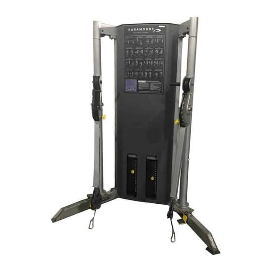
Page 1: Assembly Manual
ASSEMBLY MANUAL PFT -200 FUNCTIONAL TRAINER AM-pft-200.fm Rev 07-19-10... -
Page 2: Safety Requirements
17. Follow the installation guidelines provided with the products. 18. Retain these instructions for future reference. If you have any questions, do not hesitate to contact your Paramount Dealer of Paramount Fitness Corp. at (800) 721-2121 or www.paramountfitness.com. Refer to Maintenance Schedule label located on the machine for maintenance intervals. -
Page 3: Maintenance Requirements
• Hardware placement is indicated with a balloon. Refer to the hardware page for cor- responding size and configuration. • Be sure all hardware is tight before using the machine. TOOLS REQUIRED: ALLEN WRENCH 5/32” 3/16” PFT-200 Assembly Instructions PT1.fm... - Page 4 PFT-200 ASSEMBLY INSTRUCTIONS 1. The PFT-200 requires a floor area for the base frame of 65-1/2” x 40-1/2” [166 cm x 103 cm] with a minimum ceiling height of 78” [198 cm]. To accommodate the full range of the adjustable arms, a mini- mum area of 126”...
- Page 5 2. ASSEMBLING THE CATCH HOOKS & MOLDED FEET 2, 3, 4 Assemble Feet to Frame 3. WEIGHT PLATE INSTALLATION Depending upon the purchased configuration, your PFT-200 will require either (7) or (8) boxes of weights (P/N B1602). PFT-200-4 PFT-200-2 PFT-200-2H...
- Page 6 Retaining Collars (4) • Travel Stop Collars (4) • Cap Plate/Selector Bars (2) INSTALL the Weight Plates NOTE: PFT-200-2: (14) plates per stack PFT-200-2H: (16) plates per stack PFT-200-4: (16) plates per stack Then RE-INSTALL: • Cap Plate/Selector Bars •...
- Page 7 NOTE: These (2) views show the front of machine with the front cover removed for clar- ity. You DO NOT need to remove the front cover to assemble the selector pin. Assemble the selector pin lanyard to the pulley housing as shown. PFT-200-2 and PFT-200-2H PFT-200-4 (2:1 RATIO) (4:1 RATIO) PFT-200 Assembly Instructions PT2.fm...
- Page 8 CABLE ROUTING DIAGRAM PFT-200-2 (2:1 RATIO) Secure cable end with PFT-200-2H (2:1 RATIO) 3/8 x 1/2” socket head bolt CABLE ROUTING DIAGRAM PFT-200-4 (4:1) RATIO) PFT-200 Assembly Instructions PT2.fm...
-
Page 9: Weight Stack Label Installation
B2173* B2173 B2176 * NOTE: Label B2173 has 16 weight labels ranging from 10 - 85 lbs. For the PFT-200-2, discard the last two labels (80 and 85 lbs). To install weight stack labels: 1. Verify that the weights are installed properly. -
Page 10: Cable Check
4) Check the operation of each station through its full range of travel. Verify that it oper- ates smoothly without binding or chattering. Try this at a few different weight settings. TIP: After installing the weight plates, vigorously shake the weight stack to help align the weights. PFT-200 Assembly Instructions PT3.fm... -
Page 11: Machine Description
5) The PFT-200 has provisions for anchoring the unit to the floor. Due to the wide variation of flooring on which the unit can be installed, contact a qualified contractor to determine the appropriate fastening system. COMPLETE THE FULL ASSEMBLY OF THE MACHINE BEFORE ANCHORING THE UNIT TO THE FLOOR. - Page 12 PFT-200 Assembly Instructions PT3.fm...
-
Page 13: Warning Labels
Make sure locking nut is tight. Anti-Skid ASTM F1749 Paramount Pin P/n B 470 P/N B2141 Handgrips Order Paramount Service Kit P/N KIT-01 B2141 for recommended maintenance products PARAMOUNT CUSTO0MER SERVICE 1-800-721-2121 P/N B2315 B2315 B2606 PFT-200 Assembly Instructions PT3.fm... - Page 14 Contact Paramount Fitness Corp., 6450 E. Bandini Blvd., Los Angeles, California 90040-3185, before returning any defective equipment. Paramount Fitness Corp. © 2002.
-
Page 15: Hardware Bag
PFT-200 HARDWARE BAG ITEM DESCRIPTION PART # HOOK, ACCESSORY PFT2003008 1/4” LOCK WASHER C 747 1/4” FLAT WASHER C 752 BUTTON HEAD SCREW, 1/4-20 X C 675B 3/4 lg. MOLDED PARAMOUNT FOOT B 751 SELECTOR PIN, MAGNETIC B 470 SNAP HOOK...
Need help?
Do you have a question about the PFT-200 and is the answer not in the manual?
Questions and answers