Table of Contents
Advertisement
Advertisement
Table of Contents
Troubleshooting

Related Manuals for Uniflair Amico


Summary of Contents for Uniflair Amico
- Page 1 AMICO Installation Manual AMICO VERSION: 1.2 DATE: OCTOBER 2012 LANGUAGE: ENGLISH...
- Page 2 VERSION: 1.2 DATE: OCTOBER 2012 UNIFLAIR SPA POLICY IS ONE OF CONTINUOUS TECHNOLGICAL INNOVATION AND THE COMPANY THEREFORE RESERVES THE RIGHT TO AMEND ANY DATA HEREIN WITHOUT PRIOR NOTICE.
-
Page 3: Table Of Contents
Contents GENERAL INSTRUCTIONS Controlli semestrali Information contained in the manual Six-monthly checks Symbols Annual checks Storage Checks to be performed every sixty months Storage after use Cleaning and repalcing the filters Disposal Troubleshooting Disposal of the machine CHILLED WATER UNIT – CENTRIFUGAL FANS SAFETY Technical characteristics General Instructions... -
Page 4: General Instructions
CER 2002 codes to allow an easier disposal of the machine The descriptions and illustrations in this manual are unbinding; parts. "Uniflair S.p.A." reserves the right to make any alterations it WARNING! Observe the safety precautions at sees fit in order to improve the product without having to update work wearing the suitable individual protection this document. - Page 5 • AIR FILTERS • COMPRESSORS AND LIQUID SEPARATORS Remove the air filters. WARNING! Pay attention to oil contained in the - Materials: metallic net, synthetic fibre. compressors. Avoid any loss of oil during operations. If possible, dispose of oil and •...
-
Page 6: Safety
WARNING! Removal of, or tampering with, safety devices is a violation of EUROPEAN Environmental limits for use SAFETY STANDARDS. The environmental conditions for the use of Amico air conditioners are fall within the following values: WARNING! During installation authorised personnel must wear individual safety devices. -
Page 7: Introduction
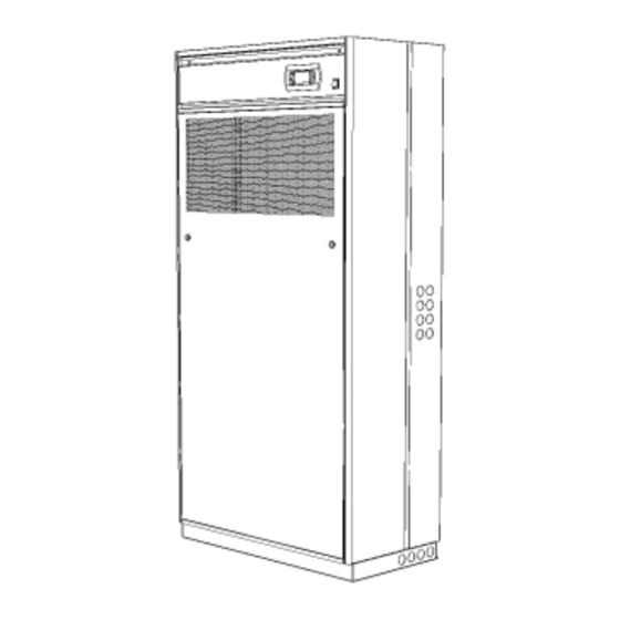
INTRODUCTION Presentation of the system The AMICO precision air conditioning units are designed for civil use and for all environments characterized by the presence of equipment with a high technological content: telephone and internet exchanges, data processing centres, meteorological rooms, laboratories and climate controlled warehouses. - Page 8 MODELS The code which distinguishes the models is composed of 4 characters: Identifying prefix of the Amico family Air discharge U = Upflow (upwards discharge) D = Downflow (downwards discharge) Operating typology C = Chilled water units A = Air cooled direct expansion units...
- Page 9 SYMBOLS APPLIED TO THE MACHINES a t l SYMBOLS APPLIED TO THE PACKAGES t i n y t i t i n t i n t i s t i n t i n s t i t f i l s t i s t i...
-
Page 10: Direct Expansion Unit - Air Cooled
DIRECT EXPANSION UNIT – AIR COOLED CENTRIFUGAL FANS Technical characteristics SDAC/SUAC Model 0151B 0151A 0251B 0251A 0331A 0351A 0501A 0601A Height 1740 1740 1740 1740 1740 1740 1740 1740 Width 1200 1200 Depth Weight Number of refrigerant circuits Number of compressors 1 -SCROLL 1 -SCROLL 1 -SCROLL 1 -SCROLL 1 -SCROLL 1 -SCROLL 1 -SCROLL 1 -SCROLL Refrigerant R410A... -
Page 11: Direct Expansion Unit - Air Cooled
DIRECT EXPANSION UNIT – AIR COOLED RADIAL FANS WITH E.C. TECHNOLOGY Technical characteristics SDAV/SUAV Model 0151B 0151A 0251B 0251A 0331A 0351A 0501A 0601A Height 1740 1740 1740 1740 1740 1740 1740 1740 Width 1200 1200 Depth Weight Number of refrigerant circuits Number of compressors 1 -SCROLL 1 -SCROLL 1 -SCROLL 1 -SCROLL 1 -SCROLL 1 -SCROLL 1 -SCROLL 1 -SCROLL Refrigerant type... -
Page 12: Operating Description
(condensers). The room unit and external condenser form an autonomous sealed circuit once installed. The UNIFLAIR remote condensers used with AMICO units include a precise electronic system to regulate the fan speed to ensure trouble-free operation throughout the year under a wide range of external air temperatures. -
Page 13: Name And Description Of The Principle Components
Name and description of the principle components Model SUA*/SUW* Model SDA*/SDW* A User terminal B Electrical panel door C Cover panel D Electrical panel E Air Filter F Fans G Cooling circuit H Brazed plate heat exchanger (present in chilled water models) - Page 14 Description of the components A - User terminal Allows the unit to be turned on or off and the configuration and visualization of the condition of the machine. • A1 LCD Display • A2 ALARM key:visualization and reset of alarms;when the alarm is activated, it flashes red •...
- Page 15 G - Cooling circuit G G3 • G1 Compressor • G2 High pressure switch • G3 Schrader Valve • G4 Low pressure transducer • G5 Shut -off valve • G6 Circuit Exit • G7 Circuit entrance • G8 Liquid receiver •...
-
Page 16: Checks To Be Made On Delivery
WARNING! The unit must be installed internally appropriate collection points. and protected from adverse conditions. The Amico unit comes packaged in a wooden case or fixed The unit is predisposed for installation on raised access flooring on a pallet and wrapped in transparent film. -
Page 17: Opening And Removal Of The Front Panel
Installation of the mounting frame Opening and removal of the front panel To install the unit on raised flooring using the mounting fra- To open and remove the front panel proceed as follows: me, carry out the following procedures: • a flexible seal at least 5 mm thick should be fitted between the raised floor panels and the mounting frame which should also be isolated from the metallic floor... -
Page 18: Electrical Connections
Internal protection panels The fan compartment and electrical heaters are protected by a sheet metal covering for safety reasons and to allow the opening of the external panels without interfering with the safety devices on the unit. SD** SU** • pass the cables inside using the power supply cable inlet Electrical connections WARNING! Electrical connection of the machine... -
Page 19: Connection To The Drains
- Signalling of the state of the unit (CV) Once the connections have been made, pour water into the condensate collection tray of the Amico unit and in the con- *P2: REMOVE WHEN “SAS” IS INSTALLED densate collection tray of the humidifier until both siphons *P3: REMOVE WHEN “ATA-BTA-AUA-BUA”... -
Page 20: Refrigerant Connections On Air Cooled Units
Refrigerant connections on air cooled units Installation guide WARNING! The pipes must always be protected from the sun. A: Discharge line B: Liquid line C: Thermal insulation Recommended connections SUA*0151 SUA*0251 SUA*0331 SUA*0351 SUA*0501 SUA*0601 SDA*0151 SDA*0251 SDA*0331 SDA*0351 SDA*0501 SDA*0601 12mm 12mm... - Page 21 (preferably less than 30 m) therefore it is possible that the internal diameter of the valves supplied by Uniflair will not coincide with the diameter of the pipes. Conforming to the Standards EN 14276-1 and EN 14276-2...
-
Page 22: Type Of Oil Recommended With Copeland Compressors
Evacuation of the refrigeration circuit and charging of Connection for water cooled units refrigerant WARNING! The laying of the lines and hydraulic WARNING! The charging and maintenance of connections must only be carried out by a the refrigeration circuit must only be carried out qualified plumber. -
Page 23: Manual Start Up And Shut Down Of The Unit
WARNING! During prolonged breaks a MANUAL START UP AND SHUT DOWN OF spontaneous migration of the refrigerant may THE UNIT occur in the casing of the compressor, which may WARNING! Check that the refrigerant circuit has cause foaming of the oil and consequent damage been filled. -
Page 24: Setting And Adjustment
SETTING AND ADJUSTMENT Selecting the power supply of the fans WARNING! Before establishing the electrical connection, make sure that the power supply is off. Also ensure that it is not possible to reconnect the power during the operation. WARNING! In the case of a unit with ducts, the load loss from the exhaust duct must be less than 100 Pa. - Page 25 Maximum available pressure depending on the fan speed regulation: S*AC S*WC 0151 0251 Air Flow 1040 1300 1400 1500 1626 [m3/h] Discharge static pressure Fan Speed [Pa] [Pa] [Pa] [Pa] [Pa] S*AC S*WC 0331 0351 Air Flow 1940 2200 2500 2700 2977 [m3/h]...
- Page 26 Maximum available pressure depending on the fan speed regulation: S*AV S*WV 0151 0251 Air Flow 1040 1300 1400 1500 1626 [m3/h] Discharge static pressure Fan Speed [Pa] [Pa] [Pa] [Pa] [Pa] S*AV S*WV 0331 0351 Air Flow 1940 2200 3205 3205 3440 [m3/h]...
-
Page 27: Setting The Regulation And Safety Devices
Setting the regulation and safety devices Setting the air flow sensor After starting up the unit, set the following set points (see The FS differential pressure switch intervenes if the fan (or the microprocessor control manual): one of the fans) stops working. •... -
Page 28: Maintanence
MAINTANENCE Cleaning and repalcing the filter To clean or change the filter proceed as follows: Three-monthly checks • rotate the closing blocks of the front panel by one quarter Carry out the following checks every three months: of a turn and remove the panel to access the air filter; •... -
Page 29: Troubleshooting
Troubleshooting Troubleshooting is made easier by the indications on the control panel display: when an alarm signal is displayed, consult the control panel instruction manual. If necessary, call the nearest Service Centre describing the nature of the fault and its possible cause displayed on the control. - Page 30 HUMIDITY CONTROL HUMIDITY CONTROL . l a . t c f n i r t l i T " . " i d i c i f y t i . t c . ) l y t i i f i t ' n .
-
Page 31: Refrigerant Circuit
REFRIGERANT CIRCUIT , t i o l f t i u n i l , t s o l f c i f o l f t a l n i l . r i n i l . s t o l f o l f c i f... - Page 32 " . " o l f . t n L " . " q i l n i l t l i f i f t e t l c i t c i t y l t b i l ) l i s t i v i t...
-
Page 33: Chilled Water Unit - Centrifugal Fans
CHILLED WATER UNIT – CENTRIFUGAL FANS Technical characteristics Model 0200B 0250B 0300B 0400B 0600B Height 1740 1740 1740 1740 1740 Width Depth Weight Air Flow 1610 2280 2305 3265 4490 E.S.P Maximum Minimum air flow 1040 1150 1940 1940 3020 Power supply voltage V/ph/Hz 230/1N/50 230/1N/50 230/1N/50 230/1N/50 230/1N/50 1) Unit in complete version (including packaging) -
Page 34: Unita' Ad Acqua Refrigerata - Ventilatori Radiali Con Tecnologia E.c
UNITA’ AD ACQUA REFRIGERATA - VENTILATORI RADIALI CON TECNOLOGIA E.C. Technical characteristics Model 0200B 0250B 0300B 0400B 0600B Height 1740 1740 1740 1740 1740 Width Depth Weight Air Flow 1610 2280 2305 3265 5035 E.S.P Maximum Minimum air flow 1040 1150 1940 1940... -
Page 35: Operating Description
CHILLED WATER UNITS (CW) The CW uses the availability of chilled water to control the room conditions. This version of AMICO has a relatively simple construction and gives outstanding reliability. The microprocessor controls the modulating action of the 3 way (or optional 2 way) chilled water valve to give accurate control. -
Page 36: Name And Description Of The Principle Components
Name and description of the principle components Model SUC* A User terminal Model SDC* B Electrical panel door C Cover panels D Electrical panel E Air Filter F Fans G Chilled water valve Description of the components A - User terminal Allows the unit to be turned on or off and the configuration and visualization of the condition of the machine. - Page 37 D - Electric panel • D1 Magnetothermic - auxiliary - heater (optional) - humidifier (optional) - fans • D2 Interface board • D3 Dirty filter sensor • D4 Air flow sensor • D5 Main switch • D6 Terminal board • D7 Input/output electrical supply cables •...
-
Page 38: Checks To Be Made On Delivery
WARNING! The unit must be installed internally appropriate collection points. and protected from adverse conditions. The Amico unit comes packaged in a wooden case or fixed The unit is predisposed to be installed on raised access flooring on a pallet and wrapped in transparent film. - Page 39 • position the Amico unit on the floor stand; • firmly grip the panel; • fix the unit to the floor stand using the M8 screw inserts •...
-
Page 40: Internal Protection Panels
Internal protection panels The fan compartment and electrical heaters are protected by a sheet metal covering for safety reasons and to allow the opening of the external panels without interfering with the safety devices on the unit. SD** SU** • pass the cables inside using the power supply cable inlet Electrical connections •... -
Page 41: Connection To The Water Drain
POWER SUPPLY CABLE DIGITAL CONFIGURABLE INPUTS (at customers at care) Terminal board 51-20 SD./SU.A-W (C-V) - User 0151A - 0251A - 0331A - 0351A - 0501A - 0601A - ON - OFF Remote SD./SU.C (C-V) - Flooding sensor (SAS) 0200A - 0250A - 0300A - 0400A - 0600A Terminal board 52-20 - User - ON-OFF Remote... -
Page 42: Hydraulic Connections
Once the connections have been made, pour water into the coil) and wait for the water to come out. condensate collection tray of the Amico unit and in the con- densate collection tray of the humidifier until both siphons are full. -
Page 43: Manual Start Up And Shut Down Of The Unit
To turn the unit off, carry out the following procedure: MANUAL START UP AND SHUT DOWN OF • on the first screen of the user terminal, press the A5 or THE UNIT A7 buttons until the SWITCH OFF UNIT screen appears; WARNING! Check that the refrigerant circuit has •... - Page 44 CENTRIFUGAL FANS Nominal fan regulation (to have the nominal airflow with ESP=20Pa) UNIT WITHOUT ELECTRICAL HEATERS UNIT WITH ELECTRICAL HEATERS Nominal speed @20Pa Minimum speed @20Pa Nominal speed @20Pa Minimum speed @20Pa Eu4 +Post Eu4 +Post Eu4 +Post Eu4 +Post Model SDCC SUCC...
- Page 45 S*CC0300* Air Flow 1150 1500 2000 2300 2339 [m3/h] Discharge static pressure Fan Speed [Pa] [Pa] [Pa] [Pa] [Pa] S*CC0400* Air Flow 1940 2500 3000 3360 3470 [m3/h] Discharge static pressure Fan Speed [Pa] [Pa] [Pa] [Pa] [Pa] S*CC0600* Air Flow 3020 3500 4000...
-
Page 46: Setting The Regulation And Safety Devices
Maximum available pressure depending on the fan speed regulation: S*CCV200* Air Flow 1040 1370 1520 1610 1956 [m3/h] Discharge static pressure Fan speed [Pa] [Pa] [Pa] [Pa] [Pa] S*CV0250* Air Flow 1150 1500 1607 2000 2358 [m3/h] Discharge static pressure Fan speed [Pa] [Pa]... -
Page 47: Setting The Air Flow Sensor
MAINTENANCE Setting the air flow sensor The FS differential pressure switch intervenes if the fan (or Three-monthly checks one of the fans) stops working. Carry out the following checks every three months: The factory set point of the FS differential pressure switch is •... -
Page 48: Cleaning And Repalcing The Filters
Cleaning and repalcing the filters Servomotor and chilled water valve To clean and replace the filters carry out the following If necessary (in the event of a fault in the servomotor or the procedures: control system) manually move the valve: •... -
Page 49: Troubleshooting
Troubleshooting Troubleshooting is made easier by the indications on the control panel display: when an alarm signal is displayed, consult the control panel instruction manual. If necessary, call the nearest Service Centre describing the nature of the fault and its possible cause displayed on the control. - Page 50 HUMIDITY CONTROL . l a . t c f n i r t l i ; l a . y l e l l c i f y l t e l l l i t i d i c i f .
-
Page 51: Accessories
ACCESSORIES Humidifier U1 Boiler cylinder U2 Water supply tray U3 High water level detector electrodes in the boiler cylinder U4 Condenser drain U5 Collector charge/discharge U6 Water input U7 Drain U8 Feed water solenoid valve U9 Boiler cylinder electric drainage valve U10 Overflow pipe (behind the cylinder) U11 Amperometric transformer for measuring the current (within the electrical panel) -
Page 52: Operating Principle
Operating principle In the electrode boiler humidifier, the current flowing between the electrodes in the water in the cylinder generates the heat necessary to boil the water. By controlling the water level and the concentration of salt measured in the steam cylinder (U1) using the feed water solenoid valve (U8) and the boiler cylinder electric drainage valve (U9), the electric current is regulated by means of an amperometric transformer (U11). -
Page 53: Maintenance
Maintenance The only maintenance required is periodic inspection and cleaning of the steam boiler components. This should be carried out at least every six months, preferably before the summer holiday shutdown. BOILER CYLINDER Limescale deposits must be cleaned periodically from the electrodes and particles of limescale must be removed from the filter at the base of the cylinder. -
Page 54: Electric Heaters
Electric heaters Amico units can be equipped with electric heaters. For each model there are two levels available: standard and improved. The finned elements are characterised by maintaining low power density of the surfaces in a highly efficient way, therefore limiting overheating of the elements and consequently increasing their lifespan. -
Page 55: Temperature And Humidity Sensor
Replacing the electrical heaters WARNING! Before replacing the electrical heaters, disconnect the power supply from the unit. Make sure that it is not possible for the power to be turned on again while they are being replaced. WARNING! The heaters must only be replaced by a qualified electrician. The total capacity of the electrical heaters is subdivided into more elements, each with a capacity equal to 2 or 3 kW based on the size of the unit. -
Page 56: Connection To Fresh Air Intake
Connection to fresh air intake The unit can be made ready for the intake of fresh air through an optional filter. The optional module for the fresh air intake, containing the filter cartridge, must be applied on the left side of the unit during the installation phase and correspond to the holes which introduce the air into the fan compartment. -
Page 57: Discharge Temperature Threshold Sensor (Only On Chilled Water Models)
Discharge temperature threshold sensor (only on CHILLED WATER models) An NTC temperature sensor is an optional accessory which maintains the supply air temperature of the unit above a threshold value. The sensor is connected to the microprocessor control system as described in the electrical diagram of the unit. - Page 58 THIS PAGE HAS INTENTIONALLY BEEN LEFT BLANK...
- Page 59 THIS PAGE HAS INTENTIONALLY BEEN LEFT BLANK...
- Page 60 UNIFLAIR S.p.A. Registered office & Viale della Tecnica, 2 Administrative Headquarters: 35026 Conselve (Pd) Italy Viale della Tecnica 2, Tel. +39 049 5388211 35026 Conselve (PD) Italy Fax +39 049 5388212 P.IVA 02160760282 info@uniflair.com C.C.I.A.A. di PD uniflair.com R.E.A. 212586 del 21/04/1988 R.I.N.
Need help?
Do you have a question about the Amico and is the answer not in the manual?
Questions and answers