Table of Contents
Advertisement
Available languages
Available languages
MANUALE DI ISTRUZIONI / INSTRUCTION MANUAL
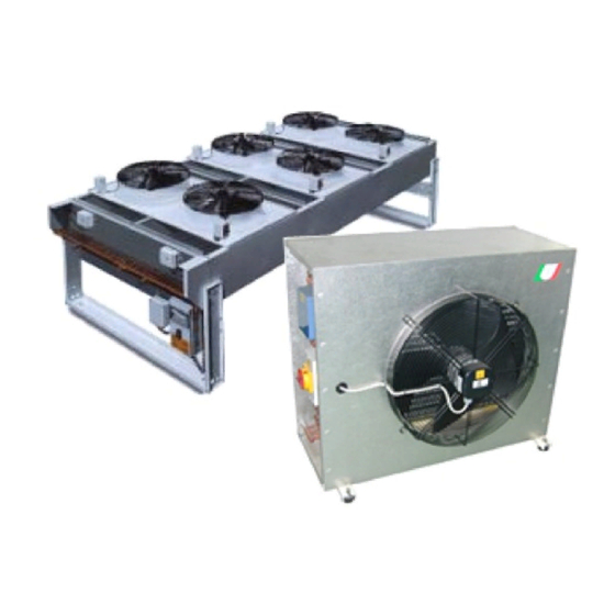
CONDENSATORI AD ARIA / AIRCOOLED CONDENSER
CAL
CONDENSATORI AD ARIA / AIRCOOLED CONDENSER
Modelli Mono-circuito / Single circuit model
0251 - 0331 - 0361 - 0511
0661 - 0801 - 1011 - 1301
Modelli Bi-circuito / Dual circuit model
1802 - 2002 - 3002 - 4002 - 5002
MANUALE DI ISTRUZIONI / INSTRUCTION MANUAL
GB
© UNIFLAIR 2004
1 (28)
CAL - Rev 2.3 – 24-02-2004 IT - EN
Advertisement
Table of Contents

Related Manuals for Uniflair CAL 0251


Summary of Contents for Uniflair CAL 0251
- Page 1 0661 - 0801 - 1011 - 1301 Modelli Bi-circuito / Dual circuit model 1802 - 2002 - 3002 - 4002 - 5002 MANUALE DI ISTRUZIONI / INSTRUCTION MANUAL © UNIFLAIR 2004 1 (28) CAL - Rev 2.3 – 24-02-2004 IT - EN...
- Page 2 The following general characteristics are relevant to standard units designed according to the available options found on the units price list. UNIFLAIR ITALIA S.p.A. Via dell’Industria, 10 35020 BRUGINE (Padova) Italy Tel. +39 (0)49 9713211 Fax.
-
Page 3: Table Of Contents
MANUALE DI ISTRUZIONI / INSTRUCTION MANUAL CONDENSATORI AD ARIA / AIRCOOLED CONDENSER Indice Pagina Simbologia Norme di sicurezza Descrizione generale Descrizione e destinazione d’uso Targa d'identificazione Trasporto e movimentazione Dimensioni e pesi Installazione Spazio operativo Dimensioni delle connessioni frigorifere Collegamenti frigoriferi Collegamenti elettrici Cavi d'alimentazione - protezioni Avviamento... -
Page 4: Simbologia
MANUALE DI ISTRUZIONI / INSTRUCTION MANUAL CONDENSATORI AD ARIA / AIRCOOLED CONDENSER SIMBOLOGIA SIMBOLO SIGNIFICATO SIMBOLO SIGNIFICATO PERICOLO GENERICO ORGANI IN MOVIMENTO AVVERTENZE IMPORTANTI SUPERFICI CALDE, PERICOLO D'USTIONE COMPONENTI TENSIONE, SUFERFICI TAGLIENTI PERICOLO ELETTRICO NORME DI SICUREZZA • Prima di qualsiasi intervento leggere attentamente il libretto d'istruzioni •... -
Page 5: Descrizione Generale
MANUALE DI ISTRUZIONI / INSTRUCTION MANUAL CONDENSATORI AD ARIA / AIRCOOLED CONDENSER DESCRIZIONE GENERALE DISPOSIZIONE CON FLUSSO D’ARIA ORIZZONTALE Fig. 1.a. - CAL 0251…1301 Fig. 1.b. - CAL 1802…5002 DISPOSIZIONE CON FLUSSO D’ARIA VERTICALE Fig. 2.a. - CAL 0251…1301 Fig. 2.b. - CAL 1802…5002... -
Page 6: Descrizione E Destinazione D'uso
MANUALE DI ISTRUZIONI / INSTRUCTION MANUAL CONDENSATORI AD ARIA / AIRCOOLED CONDENSER DESCRIZIONE E DESTINAZIONE D’USO Condensatori remoti con ventilatore assiale a basso numero di giri idonei ad installazione all’aperto, completamente assemblati e collaudati in fabbrica. I condensatori possono essere installati sia in posizione verticale (flusso aria orizzontale) oppure in posizione orizzontale (flusso aria verticale). -
Page 7: Trasporto E Movimentazione
MANUALE DI ISTRUZIONI / INSTRUCTION MANUAL CONDENSATORI AD ARIA / AIRCOOLED CONDENSER TRASPORTO E MOVIMENTAZIONE Il condensatore ha lasciato la fabbrica in perfetto stato; al momento della consegna; controllarne l’integrità e notificare subito per iscritto al trasportatore ogni danno che possa essere attribuito ad un trasporto rude. Durante il trasporto e il tiro in sito: •... -
Page 8: Spazio Operativo
MANUALE DI ISTRUZIONI / INSTRUCTION MANUAL CONDENSATORI AD ARIA / AIRCOOLED CONDENSER SPAZIO OPERATIVO Rispettare le distanze minime indicate in fig. 3, necessarie per una libera circolazione dell’aria e per la manutenzione dell’unità. > 0,7 m > 4 m > 4 m >... -
Page 9: Dimensioni Delle Connessioni Frigorifere
MANUALE DI ISTRUZIONI / INSTRUCTION MANUAL CONDENSATORI AD ARIA / AIRCOOLED CONDENSER DIMENSIONI DELLE CONNESSIONI FRIGORIFERE Il condensatore è provvisto di connessioni tipo linea del liquido linea del gas ROTALOCK maschio. 1” maschio (0251…0361) 1” maschio (0251…0361) Fig. 4.a. 1 ¼" maschio (0511…5002) 1 ¼"... -
Page 10: Collegamenti Frigoriferi
(De) dev'essere scelto in funzione della lunghezza delle stesse, pertanto non sempre coinciderà con il diametro interno (ODS) dell'attacco rotalock fornito da UNIFLAIR. Fig. 6. COLLEGAMENTI FRIGORIFERI Il condensatore è pressato in fabbrica con aria secca (modelli 0251…1301) o azoto (modelli 1802…5002) - Page 11 MANUALE DI ISTRUZIONI / INSTRUCTION MANUAL CONDENSATORI AD ARIA / AIRCOOLED CONDENSER Rispettare corretto collegamento condensatore evitando di invertire l’ingresso con l’uscita (vedi fig. 8). Fig. 8.a. Fig. 8.b. La stesura delle linee, con un percorso complessivo preferibilmente inferiore a 30 metri, deve essere realizzata da un esperto tecnico frigorista secondo le seguenti indicazioni (vedi figure).
-
Page 12: Collegamenti Elettrici
MANUALE DI ISTRUZIONI / INSTRUCTION MANUAL CONDENSATORI AD ARIA / AIRCOOLED CONDENSER COLLEGAMENTI ELETTRICI La corretta esecuzione degli allacciamenti elettrici, a regola d’arte e nel rispetto delle norme vigenti, è importante ai fini della prevenzione degli infortuni e del buon funzionamento, inalterato nel tempo, del condensatore. -
Page 13: Organi Di Regolazione - Taratura
MANUALE DI ISTRUZIONI / INSTRUCTION MANUAL CONDENSATORI AD ARIA / AIRCOOLED CONDENSER ORGANI DI REGOLAZIONE - TARATURA Il condensatore è dotato di un organo di regolazione della pressione di condensazione consistente alternativamente in: 1. Regolatore continuo di velocità (versione costruttiva P - standard 2. - Page 14 REGOLATORE DI VELOCITA’ CONDENSANTI BICIRCUITO TARATURA di fabbrica per Factory CALIBRATION for Banda Proporzionale Set-Point Soft-Start Vel. MAX Cut-Off Selezione: MODO Cut-Off MODO Vel. MIN SOFT PROP. CUT-OFF START BAND POINT 0-30 bar 0-30 bar SOFT PROP. CUT-OFF START BAND POINT 2.5 mA 100%...
- Page 15 MANUALE DI ISTRUZIONI / INSTRUCTION MANUAL CONDENSATORI AD ARIA / AIRCOOLED CONDENSER Nella parte di controllo sono presenti gli organi di regolazione, ovvero: • Trimmers : indicati con ‘Pn’ • Ponticelli : indicati con 'Jn' • Led: indicati con 'Dln' DL1 Led VERDE di segnalazione "erogazione di tensione al carico in corso"...
-
Page 16: Manutenzione
MANUALE DI ISTRUZIONI / INSTRUCTION MANUAL CONDENSATORI AD ARIA / AIRCOOLED CONDENSER MANUTENZIONE • Controllare frequentemente lo stato di pulizia del condensatore; rimuovere dallo scambiatore di calore alettato tutti i corpi estranei (foglie, semi, polvere) con un getto d’aria compressa. Le alette dello scambiatore di calore sono in lamiera di alluminio di piccolo spessore e possono tagliare in caso di contatto involontario. -
Page 17: Symbols Used
MANUALE DI ISTRUZIONI / INSTRUCTION MANUAL CONDENSATORI AD ARIA / AIRCOOLED CONDENSER SYMBOLS USED SYMBOL MEANING SYMBOL MEANING DANGER MOVING PARTS IMPORTANT WARNING HOT SURFACE LIVE COMPONENTS – RISK OF SHARP SURFACES ELECTRIC SHOCK SAFETY INSTRUCTIONS • READ THE INSTRUCTION MANUAL CAREFULLY BEFORE CARRYING OUT ANY WORK ON THE EQUIPMENT. -
Page 18: General Description
MANUALE DI ISTRUZIONI / INSTRUCTION MANUAL CONDENSATORI AD ARIA / AIRCOOLED CONDENSER GENERAL DESCRIPTION HORIZONTAL AIR DISCHARGE ARRANGEMENT Fig. 1.a. - CAL 0251…1301 Fig. 1.b. - CAL 1802…5002 VERTICAL AIR DISCHARGE ARRANGEMENT Fig. 2.a. - CAL 0251…1301 Fig. 2.b. - CAL 1802…5002... -
Page 19: Description And Use
MANUALE DI ISTRUZIONI / INSTRUCTION MANUAL CONDENSATORI AD ARIA / AIRCOOLED CONDENSER DESCRIPTION AND USE Remote condensers with axial fans for outdoor installation, fully factory assembled and tested. The condenser can be installed in a vertical position with horizontal air flow or, with the addition of appropriate brackets, in a horizontal position with vertical air flow. -
Page 20: Transport - Positioning On Site
MANUALE DI ISTRUZIONI / INSTRUCTION MANUAL CONDENSATORI AD ARIA / AIRCOOLED CONDENSER TRANSPORT - POSITIONING ON SITE The condenser leaves the factory in perfect condition, at the moment of delivery its condition should be carefully checked and any damage which might have been caused in transit should be notified in writing to the haulier. During transit and positioning on site: •... -
Page 21: Working Space
MANUALE DI ISTRUZIONI / INSTRUCTION MANUAL CONDENSATORI AD ARIA / AIRCOOLED CONDENSER WORKING SPACE Indicated in fig. 3, minimum recommended distance to be left clear for a correct unit function and to allow access to the unit for maintenance. > 0,7 m >... -
Page 22: Size Of Refrigerant Connections
MANUALE DI ISTRUZIONI / INSTRUCTION MANUAL CONDENSATORI AD ARIA / AIRCOOLED CONDENSER SIZE OF REFRIGERANT CONNECTIONS The condenser has male rotalock connections. liquid line gas line Fig. 4.a. 1” male (0251…0361) 1” male (0251…0361) 1 ¼" male (0511…5002) 1 ¼" male (0511…1802) 1 ¾"... -
Page 23: Refrigerant Connections
The size will not always coincide with the internal diameter (ODS) of the rotalock valves supplied by UNIFLAIR. Fig. 6. REFRIGERANT CONNECTIONS The condenser is factory charged with dry air (model 0251…1301) or dry nitrogen (model... - Page 24 MANUALE DI ISTRUZIONI / INSTRUCTION MANUAL CONDENSATORI AD ARIA / AIRCOOLED CONDENSER Take care that the connections are correctly made and in particular do not invert the inlet and outlet connections (fig. 8). Fig. 8.a. Fig. 8.b. It is recommended that the piping, whose total length should preferably not exceed 30 metres, be installed by an expert refrigeration operator according to the following instructions (see fig.).
-
Page 25: Electrical Connections
MANUALE DI ISTRUZIONI / INSTRUCTION MANUAL CONDENSATORI AD ARIA / AIRCOOLED CONDENSER ELECTRICAL CONNECTIONS A correct electrical connection, carried out accurately and in compliance with local regulations, is extremely important in order to prevent accidents and to ensure long trouble free operation. Before working on the electrical parts of the unit, make sure that the power is off and that the isolator switch on the electrical panel is in the “O”... -
Page 26: Control Devices - Adjustment
MANUALE DI ISTRUZIONI / INSTRUCTION MANUAL CONDENSATORI AD ARIA / AIRCOOLED CONDENSER CONTROL DEVICES - ADJUSTMENT The condenser is fitted with a condensing pressure control device which can be either: 4. Stepless speed controller (version P) - standard ); 5. ON/OFF pressure switch (CAL single circuit, version S on request );... - Page 27 FAN SPEED REGULATOR FOR BICIRCUIT CONDENSING UNIT TARATURA di fabbrica per Factory CALIBRATION for Banda Proporzionale Set-Point Soft-Start Vel. MAX Cut-Off Selezione: MODO Cut-Off MODO Vel. MIN SOFT PROP. CUT-OFF START BAND POINT 0-30 bar 0-30 bar SOFT PROP. CUT-OFF START BAND POINT...
- Page 28 MANUALE DI ISTRUZIONI / INSTRUCTION MANUAL CONDENSATORI AD ARIA / AIRCOOLED CONDENSER The following control devices are found on the control section: • Trimmers: indicated as ‘Pn’ • Jumpers: indicated as 'Jn' • Led: indicated as 'Dln' The GREEN DL1 Led signals "delivery of voltage to the load in progress" The following connection devices are found on the power section: •...
-
Page 29: Maintenance
MANUALE DI ISTRUZIONI / INSTRUCTION MANUAL CONDENSATORI AD ARIA / AIRCOOLED CONDENSER MAINTENANCE • Regularly check the state of the condenser fins; remove from them all foreign objects (leaves, feathers, seeds, dust, etc.) using a jet of compressed air. The heat exchanger fins are made of thin aluminium sheet and can cause cuts in the event of the accidental contact. - Page 30 MANUALE DI ISTRUZIONI / INSTRUCTION MANUAL CONDENSATORI AD ARIA / AIRCOOLED CONDENSER 30 (28) CAL - Rev 2.3 – 24.02.04 IT - EN...
- Page 31 MANUALE DI ISTRUZIONI / INSTRUCTION MANUAL CONDENSATORI AD ARIA / AIRCOOLED CONDENSER 31 (28) CAL - Rev 2.3 – 24-02-2004 IT - EN...
- Page 32 MANUALE DI ISTRUZIONI / INSTRUCTION MANUAL CONDENSATORI AD ARIA / AIRCOOLED CONDENSER UNIFLAIR ITALIA S.p.A. Via dell’industria, 10 35020 BRUGINE (Padova) - Italy Tel. +39 (0)49 9713211 Internet: www.UNIFLAIR.com Fax +39 (0)49 5806906 E-mail: INFO@UNIFLAIR.com 32 (28) CAL - Rev 2.3 – 24.02.04 IT - EN...
Need help?
Do you have a question about the CAL 0251 and is the answer not in the manual?
Questions and answers