Table of Contents
Advertisement
Advertisement
Table of Contents

Related Manuals for KROHNE ifc 300


Summary of Contents for KROHNE ifc 300
-
Page 2: Table Of Contents
6 - 15 Location and important notes on installation PLEASE NOTE ! Connection to power for IFC 300 versions C, F and W Electrical connection of remote sensors (primary heads) 9 - 15 1.3.1 General information on signal cables A and B, and field current cable C 1.3.2 Stripping (preparation) of signal cables A and B... -
Page 3: Ce / Emc / Standards / Approvals
Flow table Measuring accuracy / error limits Dimensions and weights • If you need to return flowmeters to KROHNE for testing or repair • Form to accompany a returned device (can be copied) CE / EMC / Standards / Approvals... -
Page 4: Safety Information
In addition, the “General conditions of sale“ forming the basis of the purchase contract are applicable. If flowmeters need to be returned to KROHNE, please note the information given on the last-but-one page of these Instructions. KROHNE regret that they cannot repair or check your flowmeter(s) unless they are accompanied by the completed form sheet. -
Page 5: Items Included With Supply
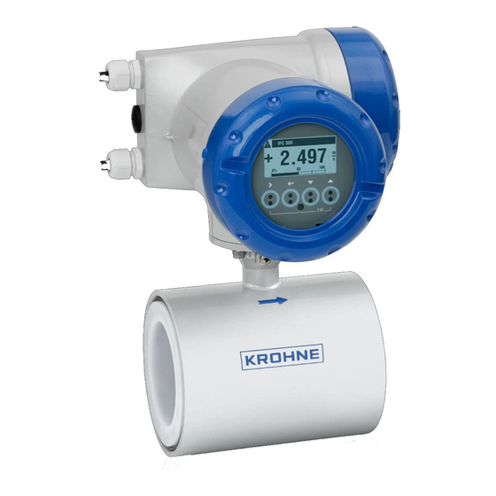
The signal converter is equipped as standard with a local display, operator control elements and ® with a HART interface IFC 300 C Compact flowmeter, signal converter mounted directly on the flow sensor IFC 300 F Signal converter in field housing, remote version,... -
Page 6: Electrical Connection: Power Supply
Sect. 1.3.3 and 1.3.5. • Use the supplied KROHNE signal cable A (type DS 300, standard) or B (type BTS 300, bootstrap, optional), standard length 5 m / 15 ft. - Page 7 The display of the IFC 300 C and IFC 300 F can be turned in steps of 90°. To do this, unscrew the cover of the electronics compartment and remove the two metal clips to the left and right of the display using a screwdriver or similar tool.
-
Page 8: Connection To Power For Ifc 300 Versions C, F And W
Connection to power for IFC 300 versions C, F and W PLEASE NOTE ! • Degree of protection IP 65 and 67 to IEC 529 / EN 60529, equivalent to NEMA 4 / 4X and 6, dependent on the version. -
Page 9: Electrical Connection Of Remote Sensors (Primary Heads)
Electrical connection of remote sensors (primary heads) 1.3.1 General information on signal cables A and B and field current cable C Proper functioning is ensured by the KROHNE signal cables A and B with double or triple foil shielding. However, when other signal cables are used, please note the following electrical data! -
Page 10: 1.3.2 Stripping (Preparation) Of Signal Cables A And B
20 / 30 do not connect only connect in the IFC 300 Signal cable A (type DS 300), with double shielding Signal cable A bending radius ≥ 50 mm / ≥ 2.0” (Slip shield over outer sheath and connect up.) -
Page 11: Type, Length And Preparation Of Field Current Cable C
300 – 600 m 1000 - 2000 ft 3 x 2.50 mm² Cu 3 x AWG 12 For the IFC 300 W the terminals are designed for the following cable cross-sections: • flexible cable: ≤ 1.5 mm² / ≤ AWG 14 •... -
Page 12: Grounding Of Sensors (Primary Heads)
Warning: The signal converter must be properly grounded to avoid personnel shock hazard. All diections, operating data and connection diagrams do not apply to devices used in hazardous areas; in such cases, read the special “Ex“ operating instructions without fail. IFC 300 03 / 2005... -
Page 13: Length Of Signal Cable Max. Distance Between Signal Converter And Sensor (Primary Head)
- 10 OPTIFLUX 6000 F 2.5 - 150 1 3000 electrical conductivity [µS/cm] Please note ! For process temperatures above 150°C, special cables and a through-box ZD are required. Optionally available, incl. modified circuit diagrams. 03 / 2005 IFC 300... -
Page 14: 1.3.6 Connection Diagrams (I And Ii) For Power Supply And Sensors
• for AC = 22 VA • for DC = 12 W These two cable terminals are not provided in the housing of the IFC 300 W, therefore, do not connect up the outer shield of cables A and C! Sensor / primary head... - Page 15 For IFC 300 W ! • IFC 300 W has 1 cover for the separate terminal compartments for power supply, sensor and for outputs and inputs. The power terminal compartment has an additional hinged flap for shock-hazard protection.
-
Page 16: Electrical Connection: Outputs And Inputs
The Modular I/O can be equipped with different output modules, depending on the task (see Modular I/O table). • For hazardous areas, all I/O variants are available for the IFC 300 C (compact) and IFC 300 F (remote) with terminal compartment in EEx - d (flameproof enclosure) or EEx - e (increased safety) protection. - Page 17 Term V/D- Terrm V/D+ Term V/D- Terrm V/D+ Field-Bus E 1 NAMUR (changeable) (EEx-i) FISCO Device FISCO Device Option Term V/D- Terrm V/D+ Term V/D- Terrm V/D+ NAMUR (changeable) FISCO Device FISCO Device Nameplate inputs/outputs Example of CG No., here: BASIC I/O 03 / 2005 IFC 300...
- Page 18 • Terminal A+ functions only for the Basic I/O. • For hazardous areas, all I/O variants for IFC 300 C and IFC 300 F are available with terminal compartment in EEx - d (flameproof enclosure) or EEx - e (increased safety) protection.
-
Page 19: Current Output
Fct. C 2.x.01 (status output). • Connection diagrams, see Sect. 2.7 Warning! All directions, operating data and connection diagrams do not apply to devices used in hazardous areas; in such cases, read the special “Ex“ operating instructions without fail! 03 / 2005 IFC 300... -
Page 20: Pulse And Frequency Output
Polarity (frequency/pulse output) and Fct. C 2.x.01 Mode (status output). • Connection diagrams see Sect. 2.7 Warning! All directions, operating data and connection diagrams do not apply to devices used in hazardous areas; in such cases, read the special “Ex“ operating instructions without fail! IFC 300 03 / 2005... -
Page 21: Status Output And Limit Switches
Fct. C 2.x.04 • Connection diagrams, see Sect. 2.7 Warning! All directions, operating data and connection diagrams do not apply to devices used in hazardous areas; in such cases, read the special “Ex“ operating instructions without fail! 03 / 2005 IFC 300... -
Page 22: Control Input
- range change • Connection diagrams, see Sect. 2.7 Warning! All directions, operating data and connection diagrams do not apply to devices used in hazardous areas; in such cases, read the special “Ex“ operating instructions without fail! IFC 300 03 / 2005... - Page 23 Notes 03 / 2005 IFC 300...
-
Page 24: Connection Diagrams (1 - 17) For Inputs And Outputs
• The following connection diagrams and operating data do not apply to hazardous-duty equipment (EEx); refer to separate operating instructions for such equipment. • Active mode: The IFC 300 supplies the power for operating (driving) the receiver instruments; note max. operating data. • Passive mode: An external power source (U ) is required to operate (drive) the receiver instruments. - Page 25 C > 19 V DC < 2.5 V DC ≤ 32 V DC 16 mA @ 24 V can also be set as status output, in which case electrical connection acc. to Diagram 4 03 / 2005 IFC 300...
- Page 26 Modular I/O and Bus I/O Connection diagrams 6 - 15 marks the terminals A, B, C or D, depending on the version of the IFC 300, see tables in Sect. 2.2. For electrical connection of the Bus Systems, please consult the separate manuals for Foundation Fieldbus, PROFIBUS PA oder DP.
- Page 27 ≤ 32 V DC 16 mA Pulse, frequency and status output / limit switch passive P to NAMUR EN 60947-5-6 Switching amplifier to NAMUR with internal voltage source Control input active C to NAMUR EN 60947-5-6 Error Signal 03 / 2005 IFC 300...
- Page 28 Basic I / O terminals A / A- only with Modular I/O terminals C / C- ® to next HART device to HART Communicator = 4 mA Multidrop I: = 4 mA ≤ 32 V DC R ≥ 230 Ω IFC 300 03 / 2005...
-
Page 29: Start-Up
Status Table in Sect. 4.8. • The display of the IFC 300 C and IFC 300 F can be turned in steps of 90°. Unscrew the cover of the electronic compartment and remove the two metal clips to the left and right of the display using a screwdriver or similar tool. -
Page 30: Operator Control Of The Signal Converter
4 optical keys then have no function signals a status message in the status list 8 Socket for connection to the KROHNE GDC bus 9 Optical interface for wireless transfer of data (input / output) • Display – for selection of menu and functions... -
Page 31: Function Of The Keys
Please note: The operating point of the 4 optical keys is located directly behind the glass pane. The most reliable way is to actuate the keys perpendicular to the front. Actuation from the side can lead to inadvertent wrong operation. 03 / 2005 IFC 300... -
Page 32: Krohne Program Structure For Emfs
Structure of KROHNE program for EMFs Select Select function and / or subfunction Meas. mode menu data ↵ > actuate for 2.5 s A 1 Language A Quick Setup A 2 Measuring point (tag) A 3 Error reset A 4 Unit... -
Page 33: Tables Of Settable Functions
Act. coil temp. B 10 Electron. temp. only visible when Fct. C 1.3.01, C 1.3.13 and C 1.3.10 activated) B 11 Act. conductivity B 12 Terminate indication(s) with ↵ Act. electr. noise B 13 Act. flow profile 03 / 2005 IFC 300... - Page 34 C 1.1.15 Settling time only when “Manual“ selected under C 1.1.14: (setting range 1 ms ≤ value ≤ 250 ms) • xxx.x ms C 1.1.16 Line frequency Select: • Automatic • 50 Hz • 60 Hz IFC 300 03 / 2005...
- Page 35 • 1 … 10 set noise suppression factor C 1.2.10 Low flow cutoff • x.xxx m/s ±x.xxx m/s (setting range 0.000 m/s < value < 10.00 m/s) value (= hysteresis) ≤ 1 value / acts on all outputs 03 / 2005 IFC 300...
- Page 36 Setting as indicated on sensor nameplate C 1.5 Simulation C 1.5.01 Flow speed Sequence, see Test Level Menu, Fct. B 1 above C 1.5.02 Volume flow Sequence, see Test Level Menu, Fct. B 2 above IFC 300 03 / 2005...
- Page 37 Text displayed Description and settings I / O C 2.1 Hardware C 2.1.01 Terminals A Assignment of terminals A - D dependent on IFC 300 version: C 2.1.02 Terminals B Outputs: • current • frequency • pulse • status • limit value Input: •...
- Page 38 • 180° shift (signal inversion possible) When Fct. C 2.5.06 Polarity is set to "both polarities“, the flow direction is indicated (e.g. +90° or -90°). C 2.x.13 Simulation For sequence, see Test Level Menu, Fct. B 1 above IFC 300 03 / 2005...
- Page 39 • 180° shift (signal inversion possible) When Fct. C 2.5.06 Polarity set to "both polarities“, flow direction is indicated (e.g. +90° or -90°). C 2.x.13 Simulation Procedure, see Test Level Menu, Fct. B 1 above 03 / 2005 IFC 300...
- Page 40 Term. A is in function! C 2.x.02 Invert signal Select: • off • on C 2.x.04 Simulation Sequence, see Test Level Menu, "B x“ above (X depends on terminal) IFC 300 03 / 2005...
- Page 41 • Français • others in preparation C 4.2.02 Contrast Setting range: -9 … 0 … +9 C 4.2.03 Default meas. page Select: • 1st meas. page • 2nd meas. page • none • status page 03 / 2005 IFC 300...
- Page 42 The correct position is indicated by the steady bright red LED of the interface, as soon as the red LED and the IR-Sensor (below the keys on the display) are roughly one above the other, see Fig. in Sect. 4.2. IFC 300 03 / 2005...
- Page 43 # @ $ % ~ ( ) [ ] • Set conversion factor: - wanted unit = [unit, see above] × conversion factor - conversion factor: max. 9 digits - shift decimal point with ↑ (to left) and with ↓ (to right) 03 / 2005 IFC 300...
-
Page 44: To Reset Counters
C 4.6 Special functions → C 4.6.01 Reset error(s)? → C 4.6.01 Reset error(s)? Select with ↑ or ↓: • No • Yes ↵ C 4.6.01 Reset error(s) Errors have been reset 4× ↵ Measuring mode IFC 300 03 / 2005... -
Page 45: General Directions For Special Measurements, Tasks And Diagnostics
Possible causes: • Meas. tube not completely filled • Deposits on bottom of measuring tube • Liner of sensor defective • Improperly installed, gaskets project e.g. into measuring tube 03 / 2005 IFC 300... -
Page 46: Special Measurements
• Liner ok? C 1.3.10 Flow profile • ON flow meas. and Shows severe bulging, counting, accuracy [U] flow erosion by abrasive dependent on the geometry profile media of the defect IFC 300 03 / 2005... - Page 47 Noisy flow indic and flow pipeline is flowing full, C 1.3.14 Limit Electr. Noise [U] electrode outputs, sensor failure noise might be an • Set e.g. to approx. 0.01 m/s noise indication of electrode corrosion 03 / 2005 IFC 300...
-
Page 48: Status Messages And Diagnostic Information
Existing hardware cannot be identified. There are Replace electronic unit either defects or unknown modules. RAM/ROM error IO1 A RAM or ROM error is detected during the CRC Defective, replace electronic unit check. or I/O module RAM/ROM error IO2 IFC 300 03 / 2005... - Page 49 Fct. C 1.1.13 acc. to sensor nameplate. DC Offset ADC overdriven by DC input level, For IFC 300 F and W: check connection of signal cable (not when pipe empty) flow measured value = 0 Current not correct,...
- Page 50 (not when coil broken) Overflow, counter 1 / 2 Counter has overrun and started again at zero. Backplane invalid The data record on the backplane is invalid. The CRC check has revealed a fault. IFC 300 03 / 2005...
- Page 51 Optical interface The optical interface is in use. The keys on the Keys are ready to operate again 60s after end of data transfer / local display are inoperative. removal of the optocoupler 03 / 2005 IFC 300...
-
Page 52: Technical Data
IFC 300 R 19” rack version Option Interfaces (for all versions) Fieldbus Foundation and PROFIBUS PA and DP IFC 300 _ / BC for Batch Control applications EEx versions: ATEX EEx Zone 1 d + e + i and EEx Zone 2... - Page 53 4 optical keys ( → ↵ ↓ ↑ ) for operator control of the Operating elements signal converter without opening the housing Infrared interface for reading and writing all parameters with KROHNE IR-Interface without opening the housing Output / input assemblies For number and possible combinations of the various outputs and inputs, refer to Sect.
- Page 54 Sum + or – counter and preset counter Time constant 0 - 100.0 s, settable as required Low-flow cutoff Value: 00.0 - 20.0 % of Q , settable 100% as required Hysteresis: ± 00.0 - 19.9 %. IFC 300 03 / 2005...
- Page 55 Term. 1, 2, 3, 4 and 20, 30, 40 (not provided in Compact Version C) Field current supply Type bipolar pulsed DC field for all KROHNE sensors (primary heads), galvanically separated from all input and output circuits Terminals Term. 7, 8 and 9 (not provided in Compact Version C) ≤...
-
Page 56: Selection Table For Krohne Sensors (Primary Heads)
Selection table for KROHNE sensors (primary heads) Sensor Meter size Special features EEx- Custody Version transfer Connection DN mm inch (various) ® OPTIFLUX 1000 DN 10 - 150 “ - 6“ Teflon PFA liner OPTIFLUX 2000 DN 25 - 3000 1“ - 120“ specifically for water ®... -
Page 57: Measuring Accuracy / Error Limits
Measuring accuracy / error limits (under reference conditions, see below) All KROHNE EMFs are calibrated by direct volumetric comparison on internationally traceable calibration rigs accredited in conformity with EN 17025. 1,0% 0,9% 0,8% 0,7% 0,6% 0,5% 0,4% 0,3% 0,2% 0,1%... -
Page 58: Dimensions And Weights
260.2 (10.2“) 202 (8.0“) (5.4“) (4.7“) (7.8“) (5.4“) 276.9 (10.9“) Wall and pipe mounting plate IFC 300 W Wall and pipe mount IFC 300 F (2.5“) (2.4“) 16 (0.6“) (Ø 0.4“) (Ø 0.4“) Several IFC 300 W mounted side by side Several IFC 300 F mounted side by side Centre-to-centre distance of mounting plates ≥... -
Page 59: If You Need To Return Flowmeters To Krohne For Testing Or Repair
KROHNE may only handle, test and repair returned devices that have been in contact with products without risk to personnel and environment. This means that KROHNE can only service this device if it is accompanied by the following certificate confirming that the device is safe to handle.
Need help?
Do you have a question about the ifc 300 and is the answer not in the manual?
Questions and answers