Table of Contents
Advertisement
Quick Links
MFC 400
MFC 400
MFC 400
MFC 400
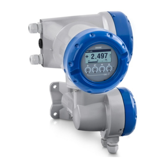
Signal converter for mass flowmeters
Description of PROFINET IO interface
Description of PROFINET IO interface
Description of PROFINET IO interface
Description of PROFINET IO interface
Electronic Revision: ER 2.0.x
The documentation is only complete when used in combination with the relevant
documentation for the flow sensor.
© KROHNE 12/2017 - 4006097501 - AD MFC 400 Profinet R01 en
Supplementary Instructions
Supplementary Instructions
Supplementary Instructions
Supplementary Instructions
Advertisement
Table of Contents

Related Manuals for KROHNE MFC 400


Summary of Contents for KROHNE MFC 400
- Page 1 Description of PROFINET IO interface Description of PROFINET IO interface Electronic Revision: ER 2.0.x The documentation is only complete when used in combination with the relevant documentation for the flow sensor. © KROHNE 12/2017 - 4006097501 - AD MFC 400 Profinet R01 en...
-
Page 2: Table Of Contents
4.7.1 I&M0 - Electronic type plate ....................18 4.7.2 I&M1 - Tags........................... 18 4.7.3 I&M2 - Installation date ......................18 4.7.4 I&M3 - Descriptor ......................... 19 4.7.5 I&M4 - Signature........................19 4.8 Units of measurement....................19 www.krohne.com 12/2017 - 4006097501 - AD MFC 400 Profinet R01 en... - Page 3 4.13.2 Status coding - Values ......................28 4.13.3 Status coding - Sensor......................28 4.14 Diagnosis ........................29 4.14.1 Diagnosis 1 .......................... 29 4.14.2 Diagnosis 2 .......................... 29 5 Notes 12/2017 - 4006097501 - AD MFC 400 Profinet R01 en www.krohne.com...
-
Page 4: Introduction
MFC 400 1.1 Scope of the document These instructions are supplementary to the standard handbook of the MFC 400 with ER 2.0.x (refer to document MA MFC 400 from version R05). They provide additional information for the devices when being operated and connected to a PROFINET IO network. -
Page 5: Device Description
1 Compact version 2 Flow sensor with connection box 3 Field housing Figure 1-2: Versions with straight tube 1 Compact version 2 Flow sensor with connection box 3 Field housing 12/2017 - 4006097501 - AD MFC 400 Profinet R01 en www.krohne.com... -
Page 6: Special Notes
This device is a digital device used exclusively as an electronic control system utilised by a public utility or in an industrial plant. INFORMATION! This PROFINET IO device is certified by the PROFIBUS Nutzerorganisation e.V. www.krohne.com 12/2017 - 4006097501 - AD MFC 400 Profinet R01 en... -
Page 7: Technical Data
- Network diagnostics via IP (SNMP) - Topology information (LLDP) with LLDP-MIB Cabling - IEC 61784-5-3 - Copper Typical application - Factory Automation - Process Automation Table 2-1: Supported PROFINET IO Conformance Class 12/2017 - 4006097501 - AD MFC 400 Profinet R01 en www.krohne.com... -
Page 8: Electrical Connections
• If the cable shield is grounded at both ends, it shall have a connection to a common ground INFORMATION! Special grounding instructions for the various flow sensors are contained in the handbook for • the signal converter. www.krohne.com 12/2017 - 4006097501 - AD MFC 400 Profinet R01 en... -
Page 9: Profinet Io Cable Types
ISO/IEC 11801 Edition 2.0 Amendment 2, Class D at least Category 5 Category (min.) ISO/IEC 11801 Edition 2.0 Connector Category 5 Shielding Cable strain relief IEC 61984 Mating cycles Min. 50 Table 3-2: Recommended cabling 12/2017 - 4006097501 - AD MFC 400 Profinet R01 en www.krohne.com... -
Page 10: Electrical Connection Of Profinet Io
Unused M12 connectors must be covered by the provided cap to protect the connector from • dust and humidity. Straight M12 connectors are recommended. • Standardised M12 connectors (IP66/67 or higher) must be used and are described in the following standards: IEC 61076-2-101 www.krohne.com 12/2017 - 4006097501 - AD MFC 400 Profinet R01 en... -
Page 11: Assembly Of The M12 Power Supply Connector With Profinet Io
3.4.3 Assembly of the M12 data connector with PROFINET IO Figure 3-2: PROFINET IO M12 data connector (female, D coded) Number Signal Colour yellow white orange blue Table 3-5: PROFINET IO M12 data connector pinout and colouring scheme 12/2017 - 4006097501 - AD MFC 400 Profinet R01 en www.krohne.com... -
Page 12: Assembly Of The Terminals With Profinet Io
Devices with two Ethernet connectors can still be used (for details refer to Overview of the PROFINET IO M12 connectors on page 10 Figure 3-3: Point-to-point or star topology www.krohne.com 12/2017 - 4006097501 - AD MFC 400 Profinet R01 en... -
Page 13: Line Topology
The control system must support this topology. This topology is typically preferred if redundancy is required. INFORMATION! Devices in this network topology need two Ethernet ports. Figure 3-5: Ring topology 12/2017 - 4006097501 - AD MFC 400 Profinet R01 en www.krohne.com... -
Page 14: Operation
A PROFINET IO General Station Description (PN-GSD) file is required for system integration. The file contains a device description written in GSD Markup Language (GSDML). The GSD file is available for download from the KROHNE website. PROFINET IO version 2.3.3... -
Page 15: Display Menu
The local display has two status LEDs dedicated to the PROFINET IO interface. Figure 4-1: Location of the status LED indication on the display for a PROFINET IO device 1 MS - Module Status LED 2 NS - Network Status LED 12/2017 - 4006097501 - AD MFC 400 Profinet R01 en www.krohne.com... -
Page 16: Module Status
Once the PROFINET IO connection is released, the write lock will be deactivated. INFORMATION! The lock jumper must not be used with the PROFINET IO communication option. Otherwise the device signals a device failure. www.krohne.com 12/2017 - 4006097501 - AD MFC 400 Profinet R01 en... -
Page 17: Interface Description
(UINT) or bit-wise (WORD) depending on context. Byte order on bus Significance Example Value = 1234 0x04 0xD2 Table 4-8: Data type Unsigned16 12/2017 - 4006097501 - AD MFC 400 Profinet R01 en www.krohne.com... -
Page 18: Information & Maintenance (I&M)
Table 4-10: Description of I&M1 4.7.3 I&M2 - Installation date I&M2 parameters can be changed by user. Name Length Description INSTALLATION_DATE Date of installation or commissioning. Table 4-11: Description of I&M2 www.krohne.com 12/2017 - 4006097501 - AD MFC 400 Profinet R01 en... -
Page 19: I&M3 - Descriptor
No - The local display is not locked. Device settings can be modified through the local display during an active PROFINET IO connection. Table 4-14: Parameter group - General 12/2017 - 4006097501 - AD MFC 400 Profinet R01 en www.krohne.com... -
Page 20: Process Input - Flow
Minimum temperature for variable "Temperature". Unit: selected by ID 54 Max. Temperature Float32 Maximum temperature for variable "Temperature". Unit: selected by ID 54 Table 4-17: Parameter group - Process Input - System Control www.krohne.com 12/2017 - 4006097501 - AD MFC 400 Profinet R01 en... -
Page 21: Process Input - Concentration
Squared temp. corr. Concentration 2 - Coefficient 11 Float32 Linear dens. corr. Concentration 2 - Coefficient 12 Float32 Squared dens. corr. Table 4-18: Parameter group - Process Input - Concentration 12/2017 - 4006097501 - AD MFC 400 Profinet R01 en www.krohne.com... -
Page 22: Unit
Unit: selected by ID 51 LFC Mass - Hysteresis Float32 Low flow cutoff hysteresis if measurement is set to "Mass flow". Unit: selected by ID 51 Table 4-20: Parameter group - Totalizer 1 www.krohne.com 12/2017 - 4006097501 - AD MFC 400 Profinet R01 en... -
Page 23: Totalizer 2
Process-dependent threshold of the 2 phase signal status message 1. 0 disables detection of 2 phase flow. Table 4-22: Parameter group - Status and Diagnostics 1 For usage of concentration measurement, please order the "Concentration package". 12/2017 - 4006097501 - AD MFC 400 Profinet R01 en www.krohne.com... -
Page 24: Cyclic Data
The totalizer can be controlled by the corresponding control octet in the output data (for details Output data refer to on page 26). 4.10.3 Generic blocks The generic blocks provide device status information and internal device diagnosis. www.krohne.com 12/2017 - 4006097501 - AD MFC 400 Profinet R01 en... -
Page 25: Input Data
Value Float32 Flow Status Unsigned16 Unit Code Unsigned16 Sensor Generic Status Unsigned16 Device Generic Status Unsigned16 Diagnosis Generic Diag 1 Unsigned8 Diag 2 Unsigned8 Table 4-23: Cyclic input data 12/2017 - 4006097501 - AD MFC 400 Profinet R01 en www.krohne.com... -
Page 26: Output Data
This example assumes a constant flow that is being totalized. Figure 4-2: Example for totalizer control X: time Y1: totalizer value Y2: totalizer run/stop Y3: totalizer reset Value Description STOP RESET www.krohne.com 12/2017 - 4006097501 - AD MFC 400 Profinet R01 en... -
Page 27: Zero Point Calibration
Related (accuracy not guaranteed). GOOD - Maintenance 0x00 0xA4 Maintenance required. Maintenance Required Required (0x04) GOOD 0x00 0x80 Valid process value. None (0x00) Table 4-25: Status coding - Device 12/2017 - 4006097501 - AD MFC 400 Profinet R01 en www.krohne.com... -
Page 28: Status Coding - Values
25, No. 12) according to the following table: Description Zero Calibration Running Stop Mode Standby Mode System Control Active Sensor Simulation Active Table 4-27: Status coding - Sensor www.krohne.com 12/2017 - 4006097501 - AD MFC 400 Profinet R01 en... -
Page 29: Diagnosis
E.g. if density unit (ID 53) changes, the values of parameters ID 10, ID 15 and ID 16 must be converted to the new unit manually. Reserved Table 4-29: Diagnosis 2 12/2017 - 4006097501 - AD MFC 400 Profinet R01 en www.krohne.com... -
Page 30: Notes
NOTES MFC 400 www.krohne.com 12/2017 - 4006097501 - AD MFC 400 Profinet R01 en... - Page 31 NOTES MFC 400 12/2017 - 4006097501 - AD MFC 400 Profinet R01 en www.krohne.com...
- Page 32 • Process Analysis • Services Head Office KROHNE Messtechnik GmbH Ludwig-Krohne-Str. 5 47058 Duisburg (Germany) Tel.: +49 203 301 0 Fax: +49 203 301 10389 info@krohne.com The current list of all KROHNE contacts and addresses can be found at: www.krohne.com...
Need help?
Do you have a question about the MFC 400 and is the answer not in the manual?
Questions and answers