Table of Contents
Advertisement
11/97
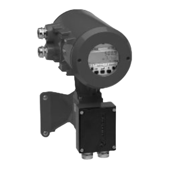
Signal converters
for
electromagnetic flowmeters
How to use these Instructions
The flowmeters are supplied ready for operation.
The primary head must be installed in the pipeline as described in the installation
instructions inside the packing of the primary head.
- Installation location and connection to power (Section 1)
- Electrical connection of outputs and inputs (Section 2)
- Factory settings and start-up (Section 3)
Power the flowmeter. THAT'S ALL. The system is operative.
Operator control of the IFC 090 signal converter is described in Sections 4 and 5.
Pull-out condensed instructions are located in the centrefold of this manual, pages A – D.
3.1M61EA3 119721
Installation and
operating
instructions
IFC 090 K
IFC 090 F
Pages 1/1-1/6
Pages 2/1-2/6
Pages 3/1-3/2
Order No. DIN A4: 7.02144.33.00
US size: 7.02144.73.00
Advertisement
Table of Contents

Related Manuals for KROHNE IFC 090 K


Summary of Contents for KROHNE IFC 090 K
- Page 1 Installation and operating Signal converters instructions electromagnetic flowmeters IFC 090 K IFC 090 F How to use these Instructions The flowmeters are supplied ready for operation. The primary head must be installed in the pipeline as described in the installation instructions inside the packing of the primary head.
-
Page 2: Table Of Contents
Switch-on and measurement Factory settings Part B IFC 090 / D Signal converter 4/1-5/14 Operation of the signal converter 4/1-4/12 Krohne operator control concept Operating and check elements Function of keys 4/3-4/4 Table of settable functions 4/5-4/9 Error messages in measuring mode... - Page 3 Error limits at reference conditions 10/2 10.4 IFC 090 Signal converter 10/3-10/4 10.5 Instrument name plates 10/5 Measuring principle and function of the system 11/1 Block diagram - signal converter 12/1 Part E Index E1-E2 Printed form to accompany flowmeters returned to Krohne...
- Page 4 Here you can note down the settings of the signal converter ! Fct. No. Function Settings 1.01 Full-scale range 1.02 Time constant 1.03 Low-flow cut-off - ON: - OFF: 1.04 Display Flow Totalizer Messages 1.05 Current output I Function Reverse range Range I Error 1.06...
-
Page 5: System Description
In addition, the “General conditions of sale” forming the basis of the purchase contract are applicable. If flowmeters need to be returned to Krohne, please note the information given on the last-but-one page of these Instructions. Krohne regrets that it cannot repair or check your flowmeter(s) unless accompanied by the completed form sheet. -
Page 6: Part A System Installation And Start-Up
Refer to Sect. 1.3.4 for maximum permissible length of signal and field current cables. • Use the supplied Krohne signal cable A (Type DS), standard length 10 m (33 ft). • Always calibrate primary head and signal converter together. Therefore, when installing, ensure primary constant GK is identical;... -
Page 7: Connection To Power
Connection to power PLEASE NOTE ! • Rated values: The flowmeter housings protecting the electronic equipment from dust and moisture must always be kept closed. The selected creepage distances and clearances have been dimensioned in conformity with VDE 0110 and IEC 664 for contamination category 2. -
Page 8: Electrical Connection Of Separate Primary Head (F Version)
Electrical connection of separate primary head (F Versions) 1.3.1 General information on signal cable A and field current cable C Use of the Krohne signal cable A with foil screen and magnetic shield will ensure proper operation of the equipment. -
Page 9: Grounding Of Primary Head
Grounding of primary head 1.3.3 • All flowmeters must be properly grounded. • The grounding conductor should not transmit any interference voltages. • Do not ground any other electrical device together with this conductor. • In hazardous locations, the grounding conductor is used simultaneously for equipotential bonding. - Page 10 1.3.4 Cable lengths (max. distance between signal converter and primary head) Abbreviations and explanatory notes used in the following tables, diagrams and connection diagrams A Signal cable A (type DS), with double shielding, see diagram for max. length C Field current cable C, with single shielding, type and length see Table D High-temperature silicone cable, 3 ×...
-
Page 11: Connection Diagrams I And Ii (Power Supply, Converter And Primary Head)
Connection diagrams I and II (power supply, converter and primary head) 1.3.5 Important information PLEASE NOTE ! • The figures in brackets indicate the stranded drain wires for the shields, see cross-sectional drawing of signal cable in Section 1.3.1. • Electrical connection to VDE 0100 ”Regulations governing heavy-current installations with line voltages up to 1000 V“... -
Page 12: Electrical Connection Of Outputs And Inputs
Electrical connection of outputs and inputs Combinations of outputs and inputs Assignment of the binary outputs and inputs as required, see 3.07 Fct. “HARDWARE” and Sect. 3.2 “Factory settings”. Current output I – active or passive mode – internal power source for the binary outputs and inputs Binary outputs/inputs –... -
Page 13: Pulse Output B1 (Terminals B1 / B⊥)
Pulse output B1 (terminals B1 / B⊥) • The pulse output is galvanically isolated from the current output and all input circuits. • Setting data and functions can note down on page 0/3. Please also refer to Sect. 3.2 “Factory settings” and Sect. 2.1 “Combinations of the binary outputs and inputs”, Fct. -
Page 14: Status Outputs B1 And B2 (Terminals B1 / B⊥ And B2 / B⊥)
Status outputs B1 and B2 (terminals B1 / B⊥ and B2 / B⊥) • The status outputs are galvanically isolated from the current output and all input circuits. • Setting data and functions can note down on page 0/3. Please also refer to Sect. 3.2 “Factory settings” and Sect. 2.1 “Combinations of binary outputs and inputs”, Fct. -
Page 15: Control Inputs B1 And B2 (Terminals B1 / B⊥ And B2 / B⊥)
Control inputs B1 and B2 (terminals B1 / B⊥ and B2 / B⊥) • The control inputs are galvanically isolated from the current output and all input circuits. • Setting data and functions can note down on page 0/3. Please also refer to Sect. 3.2 “Factory settings” and Sect. 2.1 “Combinations of binary outputs and inputs”, Fct. -
Page 16: 2.6 Connection Diagrams For Outputs And Inputs
2.6 Connection diagrams for outputs and inputs Milliammeter Key, N/O contact Totalizer Relay for forward/reverse – electronic (EC) flow measurement (F/R) – electromechanical (EMC) and/or automatic range change (BA) with 1 or 2 changeover contacts DC voltage, external power source (U Please note! This terminal is not note connection polarity provided for hazardous-duty signal... - Page 17 F/R flow measurement and P (B1) active passive F/R changeover via S (B2) passive ≤ 32 V DC / ≤ 24 V AC Relay type ≤ 150 mA e.g. Siemens D1 Automatic range change (BA) with F/R flow measurement / BA changeover via S2 (B2) / F/R changeover via S1 (B1) active...
-
Page 18: Start-Up
Start-up Switch-on and measurement • Before powering the system, please check that it has been correctly installed according to Sect. 1 and 2. • The flowmeter is delivered ready for operational use. All operating data have been factory set in accordance with your specifications. Please refer to Sect. -
Page 19: Factory Settings
Factory settings All operating data are factory set according to your order specifications. If you have not made any particular specifications at the time of ordering, the instruments will be delivered with the standard parameters and functions listed in the Table below. To facilitate easy and rapid initial start-up, current output and pulse output are set to process flow measurement in “2 flow directions”, so that the current flowrate is displayed and the volumetric flow counted independent of the flow direction. -
Page 20: Part B Ifc 090 / D Signal Converter
IFC 090 _ / D Signal converter Part B Operation of the signal converter 4.1 Krohne operator control concept Measuring mode 1 3 6. 4 9 m 3 / h r → When this display appears, press following keys: CodE 1 →... -
Page 21: Operating And Check Elements
Operating and check elements IFC 090 D Operator control by way of ..the 3 keys 4 . The keys are Σ Σ Flow – accessible after unscrewing the cover Overrange rate Totalizer of the electronic section using the special wrench (supplied). -
Page 22: Function Of Keys
Function of keys The cursor (flashing part of display) has a grey background in the following descriptions. To start operator control Operator control mode Measuring mode → 1 3 . 5 7 1 F c t . 1. 0 0 m 3 / h r O P E R A T I O N PLEASE NOTE: When “YES”... - Page 23 To change numbers select next number ↑ 3 9 7. 3 5 3 9 7. 4 5 m 3 / h r m 3 / h r To shift cursor (flashing position) shift to right → 3 9 7. 3 5 3 9 7.
-
Page 24: Table Of Settable Functions
Table of settable functions Abbreviations used B1/ B2 Status output, control input actual flowrate Nominal size, meter size 100% flow = full scale range 100% π = 1/2 x pulse width [s] / max. full-scale range (Q ≤ 1 kHz, if “AUTO” or “SYM.” is selected 100% at v = 12 m/s / 40 ft/s... - Page 25 Fct. Text Description and settings 1.04 DISPLAY Display functions → DISP.FLOW Select flow display • NO DISP. • user unit, factory set is “Liter/hr” or “US MGal/day (see Fct. 3.05) • m3/hr • PERCENT • Liter/Sec • BARGRAPH (value and bargraph display in %) •...
- Page 26 Fct. Text Description and settings 1.06 PULS B1 Pulse output B1 (see Fct. 3.07 HARDWARE) → FUNCT. P Select function for pulse output P • OFF (switched off) • 1 DIR. (1 flow direction) • 2 DIR. (forward/reverse flow, F/R flow measurement) Press key ↵...
- Page 27 Fct. Text Description and settings 2.00 TEST Test menu 2.01 TEST Q Test measuring range Q Precautionary query Press ↵ key to return to Fct. 2.01 “TEST Q”. • SURE NO Press ↵ key, then use ↑ key to • SURE YES select value: -110 / -100 / -50 / -10 / 0 / +10 / +50 / +100 / +110 PCT.
- Page 28 Fct. Text Description and settings 3.03 ZERO SET Zero calibration Note: Carry out only at “0” flow and with completely filled measuring tube! Precautionary query Press ↵ key to return to Fct. 3.03 “ZERO SET”. • CALIB. NO • CALIB. YES Press ↵ key to start calibration. Duration approx.
-
Page 29: Error Messages In Measuring Mode
Error messages in measuring mode The following list gives all errors that can occur during process flow measurement. Errors shown in display when “YES” set in Fct. 1.04 DISPLAY, subfunction “DISP. MSG.”: Error messages Description of error Error clearance LINE INT. Power failure Note: Cancel error in RESET-QUIT menu no counting during power failure... -
Page 30: Reset Totalizer And Cancel Error Messages, Reset/Quit Menu
Reset totalizer and cancel error messages, RESET/QUIT menu Cancel error messages in RESET / QUIT menu Display Description - - - - - - - - - - - - / - - - Measuring mode ↵ CodE 2 Key in entry code 2 for RESET/QUIT menu: ↑... -
Page 31: Examples Of Setting The Signal Converter
Examples of setting the signal converter The cursor, flashing part of display, is shown below in bold type. • Change measuring range of current output and value for error messages (Fct. 1.05): • Change measuring range from 04-20 mA to 00-20 mA •... -
Page 32: Description Of Functions
Description of functions Full-scale range Q 100% Fct. 1.01 FULL SCALE Press → key. Choice of unit for full-scale range Q 100% • m3/hr (cubic metres per hour) • Liter/Sec (litres per second) • US.Gal/min (US gallons per minute) • User-defined unit, factory-set is „Liter/hr“... -
Page 33: Low-Flow Cutoff
Low-flow cutoff Fct. 1.03 L.F.CUTOFF Press → key. Choice • (fixed tripping point: ON = 0.1 % / OFF = 0.2 %) • PERCENT (variable tripping points: ON = 1 - 19 % / OFF = 2 - 20 %) Select with ↑... -
Page 34: Internal Electronic Totalizer
Setting of totalizer format • Auto (exponent notation) • # . ####### • ##### . ### • ## . ###### • ###### . ## • ### . ##### • ####### . # • #### . #### • ######## Select with key ↑ . Press ↵... -
Page 35: Current Output I
Current output I Fct. 1.05 CURRENT I Press → key. → FUNCT. I = Select function for current output, press → key • (switched off, no function) • 1 DIR. (1 flow direction) • 2 DIR. (2 flow directions, F/R mode, forward/reverse) Select using ↑... -
Page 36: 5.7 Pulse Output B1
5.7 Pulse output B1 NOTE! Check whether under Fct. 3.07 “HARDWARE” the output terminal “B1” is defined as pulse output, refer also to Sect. 2.2 and Sect. 5.16. Fct. 1.06 PULS B1 Press key → . → FUNCT. P = select function for pulse output, press → key •... - Page 37 → VALUE P = set pulse value per unit volume (appears only when “PULSE/VOL.” set under “SELECT P”, press → key. • XXXX PulS/m3 • XXXX PulS/Liter • XXXX PulS/US.Gal • XXXX PulS/ user unit, factory-set: “Liter” or “US MGal”, see Sect. 5.13. Select using ↑...
-
Page 38: Status Outputs B1 And B2
Status outputs B1 and B2 NOTE: Check whether under Fct. 3.07 “HARDWARE” the output terminal “B1” and/or “B2” is defined as status output B1 and/or B2, refer also to Sect. 2.1 and Sect. 5.16. Fct. 1.06 and/or 1.07 STATUS B1 and/or B2 Press key →... -
Page 39: Control Inputs B1 And B2
Control inputs B1 and B2 NOTE! Check whether under Fct. 3.07 “HARDWARE” the output terminal “B1” and/or “B2” is defined as control input B1 and/or B2, refer also to Sect. 2.1 and Sect. 5.16. Fct. 1.06 and 1.07 CONTROL B1/B2 Press key →... -
Page 40: Primary Head
5.12 Primary head Fct. 3.02 FLOW METER Press → key. → DIAMETER = set meter size (see instrument nameplate) press → key Select size from table of meter sizes: • DN 2.5 - 1000 mm equivalent to - 40 inch Select using ↑... -
Page 41: User-Defined Unit
User-defined unit 5.13 Fct. 3.05 USER UNIT Press → key. → TEXT VOL = set text for user-defined unit, press → key • Liter (max. 5 characters, factory-set: “Liter” or “US MGal”) Characters assignable to each place: A-Z, a-z, 0-9, or “–” (= blank character) Change flashing place (cursor) using ↑... -
Page 42: F/R Mode, Forward/Reverse Flow Measurement
5.14 F/R mode, forward/reverse flow measurement • Refer to Sect. 2.6 for electrical connection of outputs. • Define direction of forward (normal) flow, see Fct. 3.02, subfunction “FLOW DIR.”: in conjunction with F/R operation, set the direction for the forward flow here. “+”... -
Page 43: Combinations Of Binary Outputs And Inputs
Combinations of binary outputs and inputs 5.16 Fct. 3.07 HARDWARE Press → key. Define function of terminal B1, press key → Select with key ↑, • PULSOUTP. (= pulse output) press key ↵ to advance to • STATUSOUTP. (= status output) terminal B2. -
Page 44: Automatic Range Change Ba
5.18 Automatic range change BA Automatic range change by means of status output Fct. 1.06 or 1.07 status output B1 or B2 (Define operating mode of output terminals, see Sect. 5.16) Press key → . Set status output B1 or B2 to automatic range change “AUTO RANGE” by pressing key ↑... -
Page 45: Applications
Applications 5.19 Fct. 3.07 APPLICAT. Press key → . Set characterization for the flow, press key → . • STEADY (flow is steady) • PULSATING (pulsating flow, e.g. due to reciprocating pumps, select function with ↑ key see also Sect. 6.4, 6.5 and 6.6 “Special-case applications”) Press ↵... - Page 46 Part C Special applications, functional checks, service, and order numbers Special applications 6.1 Use in hazardous areas Electromagnetic flowmeters with IFC 090 signal converter are approved as electrical equipment in conformity with the harmonized European Standards and Factory Mutual (FM). Correspondence between the temperature classes and the temperature of the process liquid, meter size and material of the measuring tube liner is defined in the test certificate.
- Page 47 Stable signal outputs when measuring tube empty Output signals can be stabilized to values as for “zero” flow to prevent random output signals when the measuring tube is empty or when the electrodes are not wetted in the event the measuring tube is partially full.
- Page 48 6.4 Pulsating flow Application downstream of positive-displacement pumps (reciprocating or diaphragm pumps) without pulsation dampener Operator control of the signal converter for the new settings IFC 090 B (basic version) see Sect. 6.2 IFC 090 D (display version) see Sect. 4 and 5 To change settings •...
- Page 49 Unsteady display and outputs Unsteady display and outputs can occur in connection with – high solids contents, – non-homogeneity, – poor blending, or – chemical reactions still in progress in the process liquid. If, in addition, flow is also pulsating due to the use of diaphragm or reciprocating pumps, refer to Sect.
- Page 50 • multidrop (up to 15 HART devices) The burst mode is not normally used and is therefore not supported. Further information about HART is available from the HART Communication Foundation, of which Krohne is a member. Electrical connection HART connection passive...
- Page 51 The IFC 090 can be operated either via its local operator interface or by means of the HART communicator or the CONFIG program. Both operating tools are available from KROHNE. Operator control by means of the HART communicator requires a device description (DD) which we can load for you into the communicator.
- Page 52 Functional checks Zero check with IFC 090 / D signal converter, Fct. 3.03 Switch off power source before opening the housing • Set “zero” flow in the pipeline, but make sure that the measuring tube is completely filled with fluid. •...
- Page 53 (2x) 3x ↵ - - - - - - - - - - - - - / - - - Measuring mode If you need to return your flowmeter to Krohne, please refer to last but one page of these Instructions !
- Page 54 Control input D / I / P / S LED display, current output, pulse output, status output and display Before contacting Krohne Service, please read through the following tables. THANK YOU ! Part 1 Converter IFC 090 B (B = basic version), without display...
- Page 55 Krohne Service Unsteady pulse rate Electrical conductivity of Increase time constant, see product too low. Sect. 6.2 or contact Krohne Service. Group LED / I / P Fault / Symptom Cause Remedial action LED / I / P 1...
- Page 56 FATAL. ERROR Fatal Error, Replace signal converter all outputs set to “min.” (see Sect. 8.7) or contact values. Krohne Service, having first noted down hardware information and error status, see Fct. 2.02. TOTALIZER Counts lost Delete error message in (overflow, data error) RESET/QUIT.
- Page 57 Test ok, check connection cables and receiver instrument, replace if necessary. Test faulty, current output defective. Replace signal converter (see Sect. 8.7) or contact Krohne Service Current output disabled, Activate under Fct. 1.05. see Fct. 1.05 Short-circuit between current Check connection and cables, output and pulse output.
- Page 58 Test faulty, pulse output defective, replace signal converter (see Sect. 8.7) or contact Krohne Service. Current output is external Check connection and cables, voltage source, short circuit see Sect. 2.3, 2.4 + 2.7. Voltage between I + and I⊥...
- Page 59 Test faulty, status output defective, replace signal converter (see Sect. 8.7) or contact Krohne Service. Output terminal B1 or B2 Change setting under not set to “status output” Fct. 3.07 Group D/I/P/S...
- Page 60 7.5 Test of primary head Always switch off power source before opening the housing ! Required measuring instruments and tools Special wrench to unscrew the covers, a crosstip screwdriver Ohmmeter with at least 6 V range or AC voltage/resistance measuring bridge. Note: Accurate measurements in the area of the electrodes can only be obtained with an AC voltage/resistance bridge.
- Page 61 Test of signal converter using GS 8A simulator (option) GS 8A operating elements and accessories Plug for field power supply, 2-pin Plug for signal cable, 5-pin Switch, flow direction – Socket for H2 plug on cable Z Plug of cable Z Power supply ON Potentiometer “zero”...
- Page 62 Check of setpoint display Switch on power source, allow at least 15 minutes’ warm-up time. Set switch D (front panel of GS 8A) to “0” position. Adjust zero to 0 or 4 mA with the 10-turn potentiometer P (front panel of GS 8A), depending on setting in Fct.
- Page 63 / hr = 129.2 pulses/hr 100% 61.905 Deviations are permissible between 127.3 and 131.1 pulses/hr (equivalent to ± 1.5 %). If you need to return your flowmeter to Krohne, please refer to last but one page of these Instructions ! 7/12...
- Page 64 Service 8.1 Replacement of power fuses Fuse F1 in AC Versions 1 and 2 Switch off power source before opening the housing ! Unscrew cover of electronics compartment using the special wrench. If provided, remove the display unit. For this purpose, detach the two screws R and fold display unit to side. Take out old and insert new power fuse F1.
- Page 65 Retrofitting the display unit Switch off power source before opening the housing ! Unscrew the cover from the electronic compartment using the special wrench. Insert plug for display unit into socket X6 on the amplifier PCB, see diagrams in Sect. 8.5 and 8.9. Secure the plug by means of the supplied metal clip to prevent it from dropping out.
- Page 66 ± 90°. Not allowed for flowmeters of hazardous-duty (Ex) design! Available versions of flowmeters with IFC 090 K signal converter Turning the converter housing Any faults resulting from failure to follow these instructions...
- Page 67 IFC 080 and SC 80 AS: Replacement of electronic unit by IFC 090 Replacement not allowed on flowmeters of hazardous-duty design ! Please consult factory. Before dismantling the old electronic unit, please note down all converter settings and use these for the new unit after it has been installed.
- Page 68 8.9 Illustrations of the PCBs A) Amplifier PCB, standard version Solder points S1 and S3 IC 18 DATAPROM (sensor IC) S1, S3 for empty-tube cut-off, see Sect. 6.3 S2, S4 not used 2-pin plug connector, Pin 7 and 8, see Sect. 7.5 and 7.7 IMoCom bus, plug connector for connec- tion of external...
- Page 69 3.31122.02 24 V AC/DC Versions 3.31122.03 for outputs/inputs 3.31122.01 Display unit, retrofit kit for Basic version IFC 090 K / B, incl. cover with cut-out, clip and connecting cable 1.30928.33 RS 232 adapter incl. CONFIG user software to German 2.10531.00...
- Page 70 Part D Technical Data, Measuring Principle and Block Diagram IFC 110 F technical data 10.1 Full-scale range Q 100% Full-scale ranges Q 100% Flow rate Q = 100 % 6 liter/h to 33 900 m /h (0.03 - 156 000 US Gal/min), adjustable as required, equivalent flow velocity 0.3 - 12 m/s (1 - 40 ft/s) Unit /hr, Liter/Sec, US gallons/min.
- Page 71 (1) IFM 6080 K and IFS 6000 F (DN 2.5 – 4 and 1/10 – 1/6”) additional error ± 0,3% of MV (2) All Krohne signal converters undergo burn-in tests, duration minimum 20 hours at varying ambient temperatures – 20 to + 60°C/– 4 to + 140°F. The tests are controlled by computers.
- Page 72 IFC 090 Signal converter Versions K = contact F = separate, field housing IFC 090 K/B and F/B (standard) Basic version, without local display and control elements IFC 090 K/D and F/D (option) Display version, with local display and control elements...
- Page 73 Control input (passive) Function – settable for range change, totalizer reset, error reset, set outputs to min. values or hold actual output values – initiate function by “low” or “high” control signals Control signals : 24 V AC 32 V DC (any polarity) low: ≤...
- Page 74 10.5 Instrument nameplates Separate signal converter in rotatable field housing Type designation Magnetic field frequency (here: 1/6 of power Series No. supply frequency) ALTOFLUX IFC 090F /D/ /6 Holland A96 6008 Altometer Measuring range Q: 0-150 m GK: 2.706 ≤ 0.5 kOhm Current output I: 0-20 mA R P: 1000 p/s...
- Page 75 Measuring principle and function of the system The flowmeter is designed for electrically conductive fluids. Measurement is based on Faraday’s law of induction, according to which a voltage is induced in an electrically conductive body which passes through a magnetic field. The following expression is applicable to the voltage.: U = K where:...
- Page 76 Block diagram – signal converter 1 Input amplifier • overdrive-proof signal processing, processes flow peaks up to 20 m/s (65 ft/s) and more rapidly and accurately • digital signal processing and sequence control • patented, high-resolution A/D converter, digitally controlled and monitored •...
- Page 77 Index Part E Keyword Section No. Fct. No. Keyword Section No. Fct. No. F = forward flow 4.4, 5.3, 5.14 1.04-1.07 Abbreviations 1.3.2, 1.3.4, F1, F2 = fuses 8.1, 8.5 2.1, 4.4 Factory settings Accuracies 10.3 Fatal error ADC = analog-digital converter 4.5, 12 FE = functional ground 1.2, 1.3.3, 1.3.5...
- Page 78 Keyword Section No. Fct. No. Keyword Section No. Fct. No. Magnetic field frequency 4.4 + 5.11 3.02 S = Status output 2.4, 4.4, 5.8 1.06, 1.07, 3.07 Safety isolation Magnetic sensors Setting level 4.1-4.4 1.00 et seq., Main menu column 2.00 et seq., Main menus 4.1 to 4.3...
- Page 79 Due to statutory regulations concerning protection of the envi- the flowmeter is safe to handle and stating the liquid used. ronment and the health and safety of our personnel, Krohne may only handle, test and repair returned flowmeters that Krohne regret that they cannot service your flowmeter unless have been in contact with liquids if it is possible to do so with- accompanied by such a certificate.
Need help?
Do you have a question about the IFC 090 K and is the answer not in the manual?
Questions and answers