Table of Contents
Advertisement
04/98
Signal converters
for
electromagnetic flowmeters
How to use these Instructions
The flowmeters are supplied ready for operation.
The primary head must be installed in the pipeline as described in the installation
instructions inside the packing of the primary head.
- Installation location and connection to power (Section 1)
- Electrical connection of outputs and inputs (Section 2)
- Factory settings and start-up (Section 3)
- Operator control of the signal converter is described in Sections 4 and 5.
Power the flowmeter. THAT'S ALL. The system is operative.
16-page pull-out condensed instructions
are located in the centrefold of these Installation and Operation Instructions.
Contents:
Installation (Sect. 1), electrical connection (Sect. 1 + 2),
start-up (Sect. 3) and operator control of the signal converter (Sect. 4)
3.1M61EA4 049821
Installation and
operating
intructions
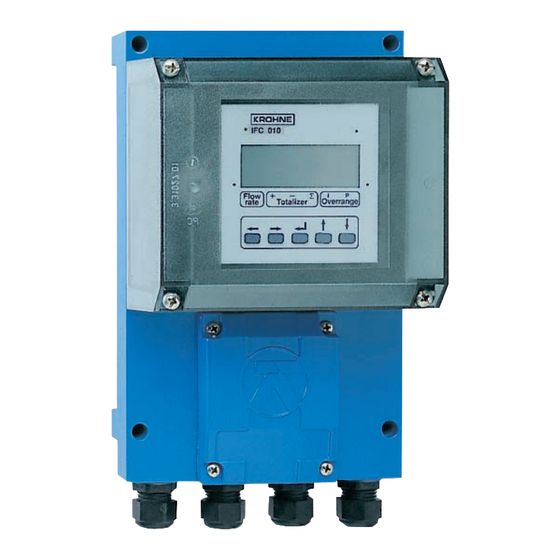
IFC 010 K
IFC 010 F
Pages 1/1-1/6
Pages 2/1-2/6
Pages 3/1-3/2
Applicable to
Software Versions
• • IFC 010 _ / D
Display version
No. 806325.07
and
No. 317551.02
and higher
• • IFC 010 _ / B
Basic version
operator-controllable
with HHT 010
No. 806323.06
and higher
Order No. 7.02140.34.00
US size: 7.02140.74.00
Advertisement
Table of Contents

Related Manuals for KROHNE IFC 010 K


Summary of Contents for KROHNE IFC 010 K
- Page 1 04/98 Installation and operating Signal converters intructions IFC 010 K electromagnetic flowmeters IFC 010 F How to use these Instructions The flowmeters are supplied ready for operation. The primary head must be installed in the pipeline as described in the installation instructions inside the packing of the primary head.
-
Page 2: Table Of Contents
Power-on and measurement Factory settings Part B IFC 010 / D Signal converter 4/1-5/14 Operation of the signal converter 4/1-4/10 Krohne operator control concept Operating and check elements Function of keys 4/3-4/4 Table of settable functions 4/5-4/9 Error messages in measuring mode... - Page 3 IFC 010 F and ZD dimensions and weights 10/4 10.5 Instrument name plates 10/5 Measuring principle and function of the system 11/1 Block diagram - signal converter 12/1 Part E Index E1-E2 Printed form to accompany flowmeters returned to Krohne...
-
Page 4: Versions Ifc 010 Signal Converter
Display version (option) with local display and control elements. All operating data factory-set to your order specifications. IFC 010 K / _ Compact flowmeter signal converter mounted direct on primary head. IFC 010 F / _ Signal converter in field housing, electrical connection to primary head via field power and signal cables. -
Page 5: System Description
In addition, the “General conditions of sale” forming the basis of the purchase contract are applicable. If flowmeters need to be returned to Krohne, please note the information given on the last-but-one page of these Instructions. Krohne regrets that it cannot repair or check your flowmeter(s) unless accompanied by the completed form sheet. -
Page 6: Part A System Installation And Start-Up
Refer to Sect. 1.3.4 for maximum permissible length of signal and field current cables. • Use the supplied Krohne signal cable A (Type DS), standard length 10 m (33 ft). • Always calibrate primary head and signal converter together. Therefore, when installing, ensure primary constant GKL is identical;... -
Page 7: Connection To Power
Connection to power PLEASE NOTE ! • Rated values: The flowmeter housings protecting the electronic equipment from dust and moisture must always be kept closed. The selected creepage distances and clearances have been dimensioned in conformity with VDE 0110 and IEC 664 for contamination category 2. -
Page 8: Electrical Connection Of Separate Primary Head (F Version)
Electrical connection of separate primary head (F Versions) 1.3.1 General information on signal cable A and field current cable C Use of the Krohne signal cable A with foil screen and magnetic shield will ensure proper operation of the equipment. - Page 9 Stripping (preparation) of signal cable A 1.3.3 Please note the different lengths given in the table for signal converter and primary head. Customer-supplied materials Length Converter Primary head W Insulation tubing (PVC), Ø 2.0 - 2.5 mm (dia. 1”) (inch) mm (inch) X Heat-shrinkable tubing or cable sleeve (2.17) 90...
-
Page 10: Cable Length (Max. Distance Between Signal Converter And Primary Head)
1.3.4 Cable lengths (max. distance between signal converter and primary head) Abbreviations and explanatory notes used in the following tables, diagrams and connection diagrams A Signal cable A (type DS), with double shielding, see diagram for max. length C Field current cable C, with single shielding, type and length see Table D High-temperature silicone cable, 3 ×... -
Page 11: Connection Diagrams I And Ii (Power Supply, Converter And Primary Head)
Connection diagrams I and II (power supply, converter and primary head) 1.3.5 Important information PLEASE NOTE ! • The figures in brackets indicate the stranded drain wires for the shields, see cross-sectional drawing of signal cable in Section 1.3.1. • Electrical connection to VDE 0100 ”Regulations governing heavy-current installations with line voltages up to 1000 V“... -
Page 12: Electrical Connection Of Outputs
Electrical connection of outputs Current output I • The current output is galvanically isolated from all input and output circuits. • Factory-set data and functions can be noted down in Sect. 5.16. Please also refer to Sect. 3.2 “Factory settings”. I+ approx. - Page 13 Connection diagrams for outputs 2.3 DC voltage, Milliammeter external power source (U Totalizer note connection polarity – electronic (EC) – electromechanical (EMC) External voltage source (U DC or AC voltage, connection polarity arbitrary Stromausgang Stromausgang active passive Active mode The current output supplies the power for operation of the outputs.
-
Page 14: Start-Up
Start-up Power- on and measurement • Before powering the system, please check that it has been correctly installed according to Sect. 1 and 2. • The flowmeter is delivered ready for operational use. All operating data have been factory set in accordance with your specifications. Please refer to Sect. -
Page 15: Factory Settings
Factory settings All operating data are factory set according to your order specifications. If you have not made any particular specifications at the time of ordering, the instruments will be delivered with the standard parameters and functions listed in the Table below. To facilitate easy and rapid initial start-up, current output and pulse output are set to process flow measurement in “2 flow directions”, so that the current flowrate is displayed and the volumetric flow counted independent of the flow direction. -
Page 16: Part B Ifc 010 / D Signal Converter
IFC 010 _ / D Signal converter Teil B Operation of the signal converter Krohne operator control concept Measuring mode 1 3 6. 4 9 m 3 / h r → When this display appears, press following keys: CodE 1 →... -
Page 17: Operating And Check Elements
Operating and check elements The controls are accessible after unscrewing the 4 screws and removing the housing cover. Display, 1st line ‚ Display, 2nd line ƒ Display, 3rd line: arrows to identify display Flowrate current flowrate Totalizer totalizer – totalizer Σ... -
Page 18: Function Of Keys
Function of keys The cursor (flashing part of display) has a grey background in the following descriptions. To start operator control Operator control mode Measuring mode → 1 3 . 5 7 1 F c t . 1. 0 0 m 3 / h r O P E R A T I O N PLEASE NOTE: When “YES”... - Page 19 To change numbers increase number ↑ 3 9 7. 3 5 3 9 7. 4 5 ↓ m 3 / h r m 3 / h r decrease number To shift cursor (flashing position) shift to right → 3 9 7. 3 5 3 9 7.
-
Page 20: Table Of Settable Functions
Table of settable functions Abbreviations used Nominal size, meter size actual flowrate Highest frequency of the pulse output 100% flow = full scale range 100% π Lowest frequency of the pulse output / max. full-scale range (Q Conversion factor volume for any unit, 100% at v = 12 m/s / 40 ft/s... - Page 21 Fct. Text Description and settings 1.04 DISPLAY Display functions → DISP.FLOW Select flow display • NO DISP. • user unit, factory set is “Liter/hr” or “US MGal/day (see Fct. 3.05) • m3/hr • PERCENT • Liter/Sec • BARGRAPH (value and bargraph display in %) •...
- Page 22 Fct. Text Description and settings 1.06 PULS.OUTP. P Pulse output P → FUNCTION P Select function for pulse output P • OFF (switched off) • 1 DIR. (1 flow direction) • 2 DIR. (forward/reverse flow, F/R measurement) Press ↵ key to transfer to subfunction “SELECT P “. →...
- Page 23 Fct. Text Description and settings 3.00 INSTALL. Installation menu 3.01 LANGUAGE Select language for display texts • GB / USA (English) • F (French) • D (German) • others on request Press ↵ key to return to Fct. 3.01 “LANGUAGE”. 3.02 FLOWMETER Set data for primary head...
-
Page 24: Error Messages In Measuring Mode
Fct. Text Description and settings 3.05 USER UNIT Set any required unit for flowrate and counting → TEXT VOL. Set text for required flowrate unit (max. 5 characters) Factory-set: “Liter” or “MGal”. Characters assignable to each place: • A-Z, a-z, 0-9, or “ – “ (= blank character). Press ↵... -
Page 25: Reset Totalizer And Cancel Error Messages, Reset/Quit Menu
Reset totalizer and cancel error messages, RESET / QUIT menu Cancel error messages in RESET / QUIT menu Display Description - - - - - - - - - - - - / - - - Measuring mode ↵ CodE 2 Key in entry code 2 for RESET / QUIT menu: ↑... -
Page 26: Description Of Functions
Description of functions Full-scale range Q 100% Fct. 1.01 FULL SCALE Press → key. Choice of unit for full-scale range Q 100% • m3/hr (cubic metres per hour) • Liter/Sec (litres per second) • US.Gal/min (US gallons per minute) • User-defined unit, factory-set is “Liter/hr“... -
Page 27: Low-Flow Cutoff
Low-flow cutoff Fct. 1.03 L.F.CUTOFF Press → key. Choice • (fixed trip points: ON = 0.1 % / OFF = 0.2 %, for 100 or 1000 Hz, see Fct. 1.06, 1% or 2%) • PERCENT (variable tripping points: ON = 1 - 19 % / OFF = 2 - 20 %) Select with ↑... -
Page 28: Internal Electronic Totalizer
Setting of totalizer format • Auto (exponent notation) • # . ####### • ##### . ### • ## . ###### • ###### . ## • ### . ##### • ####### . # • #### . #### • ######## Select with key ↑ or ↓ . Press ↵... -
Page 29: Current Output I
Current output I Fct. 1.05 CURRENT I Press → key. → FUNCT. I = select function for current output, press → key • (switched off, no function) • 1 DIR. (1 flow direction) • 2 DIR. (2 flow directions, F/R mode, forward/reverse) Select using ↑... -
Page 30: Pulse Output P
5.7 Pulse output P NOTE! Check whether under Fct. 3.07 “HARDWARE” the output terminal “B1” is defined as pulse output, refer also to Sect. 2.2 and Sect. 5.16. Fct. 1.06 PULS.OUTP. P Press key → . → FUNCT. P = select function for pulse output, press → key •... - Page 31 → VALUE P = set pulse value per unit volume (appears only when “PULSE/VOL.” set under “SELECT P”, press → key. • XXXX PulS/m3 • XXXX PulS/Liter • XXXX PulS/US.Gal • XXXX PulS/ user unit, factory-set: “Liter” or “US MGal”, see Sect. 5.12. Select using ↑...
-
Page 32: Status Output S
Status output S Fct. 1.07 IND. OUTP. S Press key → . Select function of status outputs, press → key • ALL ERROR (indicates all errors) • FATAL.ERROR (indicates fatal errors only) • (switched off, no function) • (indicates that flowmeter is operative) •... -
Page 33: Language
Language Fct. 3.01 LANGUAGE Press → key. Select language for texts in display • (German) • GB/USA (English) • (French) • others on request Select using ↑ key. Press ↵ key to return to Fct. 3.01 LANGUAGE. Entry code 5.10 Fct. -
Page 34: Primary Head
5.11 Primary head Fct. 3.02 FLOW METER Press → key. → DIAMETER = set meter size (see instrument nameplate) press → key Select size from table of meter sizes: • DN 2.5 - 1000 mm equivalent to - 40 inch Select using ↑... -
Page 35: User-Defined Unit
User-defined unit 5.12 Fct. 3.05 USER UNIT Press → key. → TEXT VOL = set text for user-defined unit, press → key • Liter (max. 5 characters, factory-set: “Liter” or “US MGal”) Characters assignable to each place: A-Z, a-z, 0-9, or “–” (= blank character) Change flashing place (cursor) using ↑... -
Page 36: F/R Mode, Forward/Reverse Flow Measurement
5.13 F/R mode, forward/reverse flow measurement • Refer to Sect. 2.6 for electrical connection of outputs. • Define direction of forward (normal) flow, see Fct. 3.02, subfunction “FLOW DIR.”: in conjunction with F/R operation, set the direction for the forward flow here. “+”... -
Page 37: Applications
Application 5.15 Fct. 3.07 APPLICAT. Press key → . → EMPTY PIPE, “function switch on“. select with ↑ or ↓ key. • • NO Press ↵ key to return to Fct. 3.07 APPLICAT. Setting data 5.16 Here you can note down the settings of the signal converter ! Fct. -
Page 38: Part C Special Applications, Functional Checks, Service, And Order Numbers
Part C Special applications, functional checks, service, and order numbers Special applications 6.1 HHT 010 hand held terminal and RS 232 adapter incl. CONFIG software (options) External operator control can be carried out with the following options: – HHT 010 hand-held terminal only for IFC 010 _ / B signal converter (basic version) –... -
Page 39: Stable Signal Outputs When Measuring Tube Empty
Stable signal outputs when measuring tube empty Output signals can be stabilized to values as for “zero” flow to prevent random output signals when the measuring tube is empty or when the electrodes are not wetted in the event the measuring tube is partially full. -
Page 40: Functional Checks
Functional checks Zero check with IFC 010 / D signal converter, Fct. 3.03 Switch off power source before opening the housing • Set “zero” flow in the pipeline, but make sure that the measuring tube is completely filled with fluid. •... -
Page 41: Hardware Information And Error Status, Fct. 2.02
(2x) 3x ↵ - - - - - - - - - - - - - / - - - Measuring mode If you need to return your flowmeter to Krohne, please refer to last but one page of these Instructions ! -
Page 42: Faults And Symptoms During Start-Up And Process Flow Measurement
Status indication output D / I / P / S LED display, current output, status output Before contacting Krohne Service, please read through the following tables. THANK YOU ! Part 1 Converter IFC 010 B (B = basic version), without display... - Page 43 – Process product Increase or switch on time – conductivity too low, constant, see Sect. 6.1, – particles/air inclusions or contact Krohne Service. – too large or inhomogeneous – Pulsating flow – Time constant too low – or switches off...
-
Page 44: With Hht
Test ok, check connection cables and receiver instrument, replace if necessary. Test faulty, current output defective. Replace signal converter (see Sect. 8.4) or contact Krohne Service Current output disabled, Activate under Fct. 1.05. see Fct. 1.05 Short-circuit between current Check connection and cables, output and pulse output. - Page 45 Test faulty, pulse output defective, replace signal converter (see Sect. 8.4) or contact Krohne Service. Current output is external Check connection and cables, voltage source, short circuit see Sect. 2.3. Voltage between I + and I⊥ approx. 15 V.
-
Page 46: Test Of Primary Head
Test of primary head Always switch off power source before opening the housing ! Required measuring instruments and tools A crosstip screwdriver Ohmmeter with at least 6 V range or AC voltage/resistance measuring bridge. Note: Accurate measurements in the area of the electrodes can only be obtained with an AC voltage/resistance bridge. -
Page 47: Test Of Signal Converter 7.6
Pin 15 of X1 replace, see Sect. 8.4, between MP 5 (solder pin) -20 . . . -27 V DC or contact Krohne and Pin 18 of X1 Service. field current supply > 1.5 V AC between Pin 7 and Pin 8... -
Page 48: Test Of Signal Converter Using Gs 8A Simulator (Option)
Test of signal converter using GS 8 A simulator (option) GS 8 A operating elements and accessories 5-to-3 pin adapter for cable C5 Plug for field power supply, 2-pin C3 / C5 Plug for signal cable, 3-pin / 5-pin – Switch, flow direction Socket for H2 plug... - Page 49 Check of setpoint display Switch on power source, allow at least 15 minutes’ warm-up time. Set switch D (front panel of GS 8A) to “0” position. Adjust zero to 0 or 4 mA with the 10-turn potentiometer P (front panel of GS 8A), depending on setting in Fct.
- Page 50 / hr = 129.2 pulses/hr 100% 61.905 Deviations are permissible between 127.3 and 131.1 pulses/hr (equivalent to ± 1.5 %). If you need to return your flowmeter to Krohne, please refer to last but one page of these Instructions ! 7/11...
-
Page 51: Service
Service Cleaning the signal converter housing 8.1 Switch off power source before cleaning ! The housing of the signal converter (material: polycarbonate, PC) may only be cleaned with a solventless detergent ! Replacement of power fuse(s) 8.2 Fuse F1 in AC Versions 1, 2 and 3 Switch off power source before opening the housing ! Refer to Sect. -
Page 52: Changeover Of Operating Voltage On Ac Versions 1, 2 And 3 (Not Dc Version)
8.3 Changeover of operating voltage on AC Versions 1, 2 and 3 (not DC Version) Switch off power source before opening the housing ! Refer to Sect. 8.5 for Figs. A-F. Unscrew the 4 recessed head screws (Fig. A), and remove transparent cover. Unscrew the recessed head screw (Fig. -
Page 53: Illustrations To Sect. 8.2 To 8.7
Illustrations to Sect. 8.2 to 8.7 Fig. G Fig. A Fig. D Fig. B Fig. E Fig. C Fig. F... -
Page 54: Turning The Display Pcb
8.6 Turning the display PCB Switch off power source before opening the housing ! Figs. A, B and D are given in Sect. 8.5. Unscrew the 4 recessed head screws (Fig. A) and remove the transparent cover. Unscrew the recessed head screw (Fig. B) and remove the black plastic cover. Unscrew the 2 recessed head screws (Fig. - Page 55 Reference point, power terminals 90° Bend cables 90° as shown in drawing Display board Version 3/ Standard IFC 010 F/D 90° Separate version Version 2 only 90° Amplifier board Version 1 / Standard IFC 010 K/D Version 4 Compact flowmeter...
-
Page 56: Illustrations Of The Pcbs
8.9 Illustrations of the PCBs A) Amplifier PCB IC 13 DATAPROM (sensor), see Sect. 8.4 MP1, MP5 Measuring points, see Sect. 7.6 S3, S6 for “empty tube” cut-out, see Sect. 6.2 Test point, see Sect. 7.6 20-pin socket connector, see Sect. 7.6 and 7.7 2-pin plug connector, pin 7 and 8, field power supply, see Sect. -
Page 57: Order Numbers
B) Power supply PCB, AC Versions 1, 2 and 3 C) Power supply PCB, DC Version Power fuse, F1, F2 Power fuses, see Sect. 8.2 or 9 for ratings see Sect. 8.2 or 9 for ratings Voltage selector, see Sect. 8.3 for Transformer voltage changeover Transformer... -
Page 58: Part D Technical Data, Measuring Principle And Block Diagram
Part D Technical data, measuring principle and block diagram Technical data 10.1 Full-scale range Q 100% Full-scale ranges Q 100% Flow rate Q = 100 % 6 liter/h to 33 900 m /h (0.03 - 156 000 US Gal/min), adjustable as required, equivalent flow velocity 0.3 - 12 m/s (1 - 40 ft/s) Unit /hr, Liter/Sec, US gallons/min. -
Page 59: Error Limits At Reference Conditions
Error limits at reference conditions 10.2 Pulse output ± F Error in % of flowrate (actual value): Curve A: DN 10 – 600 / ”- 24” v ≥ 0.4 m/s or v ≥ 1.3 ft/s : ± 0.5 % of measured value v ≥... -
Page 60: Ifc 010 Signal Converter
10.3 IFC 010 Signal converter Versions B - version without display / control unit (basic version) D - version with display / control unit Add-on equipment (option) - CONFIG software and RS 232 adapter for control via MS-DOS-PC, connection to IMoCom interface - Hand-Held-Terminal for control of basic versions - Other bus and computer interfaces on request Current output... -
Page 61: Ifc 010 F And Zd Dimensions And Weights
Housing Material polycarbonate (PC) Protection category (IEC 529/EN 60 529) IFC 010 K (compact) IP 67, equivalent to NEMA 6, same as primary head IFC 010 F (separate) IP 65, equivalent to NEMA 4 / 4X IFC 010 F and ZD dimensions and weights 10.4... -
Page 62: Instrument Nameplates
10.5 Instrument nameplates Separate signal converter in rotatable field housing Type designation Magnetic field frequency (here: 1/6 of power Series No. supply frequency) ALTOFLUX IFC 090F /D/ /6 Holland A96 6008 Altometer Measuring range Q: 0-150 m GKL: 2.706 ≤ 0.5 kOhm Current output I: 0-20 mA R P: 1000 p/s... -
Page 63: Measuring Principle And Function Of The System
Measuring principle and function of the system The flowmeter is designed for electrically conductive fluids. Measurement is based on Faraday’s law of induction, according to which a voltage is induced in an electrically conductive body which passes through a magnetic field. The following expression is applicable to the voltage.: U = K where:... -
Page 64: Block Diagram - Signal Converter
12 Block diagram – signal converter 1 Input amplifier • overdrive-proof signal processing, rapid and accurate • digital signal processing and sequence control • patented, high-resolution A/D converter, digitally controlled and monitored • high signal-to-noise ratio through low-loss field power supply 2 Field power supply •... -
Page 65: Index
Index Part E Keyword Section No. Fct. No. Keyword Section No. Fct. No. F = forward flow 4.4, 5.3 1.04-1.07 Abbreviations 1.3.2, 1.3.4, Factory settings 2.1, 4.4 Fatal error Accuracies 10.2 FE = functional ground 1.2, 1.3.2 ADC = analog-digital converter 4.5, 12 Field power supply 5.11, 10.3, 12... - Page 66 Keyword Section No. Fct. No. Keyword Section No. Fct. No. Magnetic field frequency 4.4 + 5.11 3.02 S = Status output 2.2, 2.3, 4.4, 5.7 1.06, 1.07 Safety isolation Main menu column Setting level 4.1-4.4 1.00 et seq., Main menus 4.1 to 4.3 1.00, 2.00, 3.00 2.00 et seq.,...
- Page 67 Due to statutory regulations concerning protection of the envi- the flowmeter is safe to handle and stating the liquid used. ronment and the health and safety of our personnel, Krohne may only handle, test and repair returned flowmeters that Krohne regret that they cannot service your flowmeter unless have been in contact with liquids if it is possible to do so with- accompanied by such a certificate.
Need help?
Do you have a question about the IFC 010 K and is the answer not in the manual?
Questions and answers