Sign In
Upload
Manuals
Brands
Krohne Manuals
Media Converter
ifc 300
Krohne ifc 300 Manuals
Manuals and User Guides for Krohne ifc 300. We have
3
Krohne ifc 300 manuals available for free PDF download: Handbook, Supplementary Instructions Manual
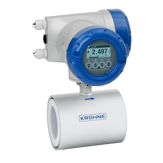
KROHNE ifc 300 Handbook (140 pages)
Signal converter for electromagnetic flowmeters
Brand:
KROHNE
| Category:
Media Converter
| Size: 4.32 MB
Table of Contents
Table of Contents
3
1 Safety Instructions
6
Software History
6
Intended Use
7
Certifications
7
Safety Instructions from the Manufacturer
8
Copyright and Data Protection
8
Disclaimer
8
Product Liability and Warranty
8
Information Concerning the Documentation
9
Warnings and Symbols Used
10
Safety Instructions for the Operator
10
2 Device Description
11
Scope of Delivery
11
Device Description
12
Field Housing
13
Wall-Mounted Housing
14
Nameplates
15
Compact Version (Example)
15
Remote Version (Example)
16
Electrical Connection Data of Inputs/Outputs (Example of Basic Version)
17
3 Installation
18
Notes on Installation
18
Storage
18
Transport
18
Installation Specifications
18
Mounting of the Compact Version
18
Mounting the Field Housing, Remote Version
19
Pipe Mounting
19
Wall Mounting
20
Turning the Display of the Field Housing Version
21
Mounting the Wall-Mounted Housing, Remote Version
22
Pipe Mounting
22
Wall Mounting
23
4 Electrical Connections
24
Safety Instructions
24
Important Notes on Electrical Connection
24
Electrical Cables for Remote Device Versions, Notes
25
Notes on Signal Cables a and B
25
Notes on Field Current Cable C
25
Requirements for Signal Cables Provided by the Customer
26
Preparing the Signal and Field Current Cables
27
Signal Cable a (Type DS 300), Construction
27
Preparing Signal Cable A, Connection to Signal Converter
28
Length of Signal Cable a
30
Signal Cable B (Type BTS 300), Construction
31
Preparing Signal Cable B, Connection to Signal Converter
31
Length of Signal Cable B
34
Preparing Field Current Cable C, Connection to Signal Converter
35
Prepare Signal Cable A, Connect to Measuring Sensor
37
Preparing Signal Cable B, Connection to Measuring Sensor
38
Preparing Field Current Cable C, Connection to Measuring Sensor
39
Connecting the Signal and Field Current Cables
40
Connecting the Signal and Field Current Cables, Field Housing
41
Connecting the Signal and Field Current Cables, Wall-Mounted Housing
42
Connecting the Signal and Field Current Cables, 19" Rack-Mounted Housing
43
Connection Diagram for Measuring Sensor, Field Housing
44
Connection Diagram for Measuring Sensor, Wall-Mounted Housing
45
Connection Diagram for Measuring Sensor, 19" Rack-Mounted Housing
46
Grounding the Measuring Sensor
47
Classical Method
47
Virtual Reference
47
Connecting Power, All Housing Variants
48
Inputs and Outputs, Overview
50
Combinations of the Inputs/Outputs (I/Os)
50
Description of the CG Number
51
Fixed, Non-Alterable Input/Output Versions
52
Alterable Input/Output Versions
54
Description of the Inputs and Outputs
55
Current Output
55
Pulse and Frequency Output
56
Status Output and Limit Switch
57
Control Input
58
Current Input
59
Electrical Connection of the Inputs and Outputs
60
Field Housing, Electrical Connection of the Inputs and Outputs
60
Wall-Mounted Housing, Electrical Connection of the Inputs and Outputs
61
19" Rack-Mounted Housing, Electrical Connection of the Inputs and Outputs
62
Laying Electrical Cables Correctly
62
Connection Diagrams of Inputs and Outputs
63
Important Notes
63
Description of the Electrical Symbols
64
Basic Inputs/Outputs
65
Modular Inputs/Outputs and Bus Systems
68
Exi Inputs/Outputs
77
HART ® Connection
82
5 Start-Up
84
Switching on the Power
84
Starting the Signal Converter
84
6 Operation
85
Display and Operating Elements
85
Display in Measuring Mode with 2 or 3 Measured Values
86
Display for Selection of Sub-Menu and Functions, 3 Lines
86
Display When Setting Parameters, 4 Lines
87
Display When Changing Parameters, 4 Lines
87
Using an IR Interface (Option)
88
Menu Structure
89
Function Tables
91
Menu A, Quick Setup
91
Menu B, Test
94
Menu C, Setup
95
Set Free Units
111
Description of Functions
112
Reset Counter in Quick Setup Menu
112
Deleting Error Messages in the Quick Setup Menu
112
Status Messages and Diagnostic Information
113
7 Service
118
Spare Parts Availability
118
Availability of Services
118
Returning the Device to the Manufacturer
118
General Information
118
Form (for Copying) to Accompany a Returned Device
119
Disposal
119
8 Technical Data
120
Measuring Principle
120
Technical Data
121
Operating Conditions
123
Installation Conditions
123
Inputs and Outputs
125
Dimensions and Weights
133
Housing
133
Mounting Plate, Field Housing
134
Mounting Plate, Wall-Mounted Housing
134
Flow Tables
135
Accuracy
137
9 Notes
138
Advertisement
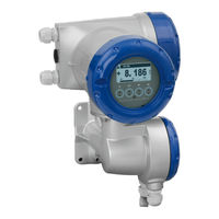
Krohne ifc 300 Handbook (59 pages)
signal converter for electromagnetic flowmeter
Brand:
Krohne
| Category:
Media Converter
| Size: 1.31 MB
Table of Contents
Table of Contents
2
CE / EMC / Standards / Approvals
3
Safety Information
4
System Description
4
Product Liability and Warranty
4
Items Included with Supply
5
Signal Converter Versions and Device Nameplates
5
1 Electrical Connection: Power Supply
6
Location and Important Notes on Installation PLEASE NOTE
6
Connection to Power for IFC 300 Versions C, F and W
8
Electrical Connection of Remote Sensors (Primary Heads)
9
1.3.1 General Information on Signal Cables a and B and Field Current Cable C
9
1.3.2 Stripping (Preparation) of Signal Cables a and B
10
Type, Length and Preparation of Field Current Cable C
11
Grounding of Sensors (Primary Heads)
12
Length of Signal Cable Max. Distance between Signal Converter and Sensor (Primary Head)
13
1.3.6 Connection Diagrams (I and II) for Power Supply and Sensors
14
Please Note
14
2 Electrical Connection: Outputs and Inputs
16
I / O Assemblies
16
Current Output
19
Pulse and Frequency Output
20
Status Output and Limit Switches
21
Control Input
22
Connection Diagrams (1 - 17) for Inputs and Outputs
24
3 Start-Up
29
4 Operator Control of the Signal Converter
30
Display, Operating and Control Elements
30
Function of the Keys
31
KROHNE Program Structure for Emfs
32
Quick Setup
32
Tables of Settable Functions
33
To Reset Counters
44
To Delete Error Messages
44
General Directions for Special Measurements, Tasks and Diagnostics
45
Special Measurements
46
Special Measurement Tasks and Diagnostics
46
Status Messages and Diagnostic Information
48
5 Technical Data
52
IFC 300 Signal Converter
52
Selection Table for KROHNE Sensors (Primary Heads)
56
Flow Table
56
Measuring Accuracy / Error Limits
57
Dimensions and Weights
58
If You Need to Return Flowmeters to KROHNE for Testing or Repair
59
Form to Accompany a Returned Device (Can be Copied)
59
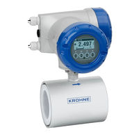
KROHNE ifc 300 Supplementary Instructions Manual (28 pages)
Signal converter for electromagnetic flowmeters
Brand:
KROHNE
| Category:
Measuring Instruments
| Size: 1.31 MB
Table of Contents
Table of Contents
2
Introduction
4
Scope of the Document
4
Used Abbreviations
4
Device Description
5
Special Notes
5
Technical Data
6
PROFINET IO General Information
6
Electrical Connections
7
Safety Instructions
7
Shielding and Grounding
7
PROFINET IO Cable Types
8
Electrical Connection of PROFINET IO
9
Overview of the PROFINET IO M12 Connectors
9
Assembly of the M12 Power Supply Connector with PROFINET IO
10
Assembly of the M12 Data Connector with PROFINET IO
10
Assembly of the Terminals with PROFINET IO
11
Topology of PROFINET IO Networks
11
Point-To-Point or Star Topology
11
Line Topology
12
Ring Topology
12
Operation
13
System Integration
13
Default Communication Settings
13
Device Discovery and Identification (DCP Signal)
13
Display Menu
14
Interface Description
14
Data Types and Byte Order
15
Float32
15
Unsigned8
15
Unsigned16
15
Information & Maintenance (I&M)
16
I&M0 - Electronic Type Plate
16
I&M1 - Tags
16
I&M2 - Installation Date
16
I&M3 - Descriptor
17
I&M4 - Signature
17
Units of Measurement
17
Start-Up Parameter Configuration
17
General Settings
18
Measurement Settings
18
Unit Settings
19
Totalizer 1 Settings
20
Totalizer 2 Settings
20
Cyclic Data
21
Measurement Blocks
21
Totalizer Blocks
21
Diagnosis Blocks
21
Cyclic Data Structure
22
Input Data
22
Output Data
24
Totalizer
25
Status Information
26
Notes
27
Advertisement
Advertisement
Related Products
KROHNE IFC 090 K
KROHNE IFC 090 F
KROHNE IFC 010 K
KROHNE IFC 010 F
KROHNE IFC 070
KROHNE IFC 050
KROHNE IFC 090
KROHNE IFC 090 i
KROHNE IFC100
KROHNE IFC 020 F
Krohne Categories
Measuring Instruments
Transmitter
Accessories
Switch
Media Converter
More Krohne Manuals
Login
Sign In
OR
Sign in with Facebook
Sign in with Google
Upload manual
Upload from disk
Upload from URL