Table of Contents
Advertisement
Quick Links
PD6700 Field-Mount Loop-Powered Process Meter
Instruction Manual
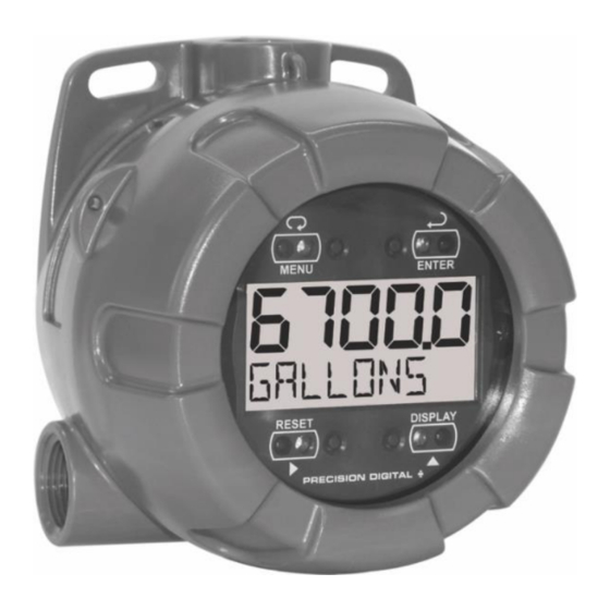
• NEMA 4X, IP66 Loop-Powered Field-Mount Process Meter
• 4-20 mA Input with ±0.03% Accuracy
• 3.0 Volt Drop (6.0 Volt Drop with Backlight)
• Easy Field Scaling in Engineering Units without Applying an Input
• 0.7" (17.8 mm) 5 Digits Upper Display
• 0.4" (10.2 mm) 7 Alphanumeric Characters Lower Display
• Display Mountable at 0°, 90°, 180°, & 270°
• SafeTouch
Through-Window Button Programming
TM
• HART
®
Protocol Transparent
• Loop or External DC-Powered Backlight Standard
• Operating Temperature Range: -40 to 75°C (-40 to 167°F)
• Conformal Coated PCBs for Dust and Humidity Protection
• Password Protection
• 32-Point Linearization, Square Root Extraction and Programmable Exponent Function
• Wide Viewing Angle
• Flanges for Wall or Pipe Mounting
• Plastic NEMA 4X, IP66 Enclosure
• Three 3/4" NPT Threaded Conduit Openings (Two Plugs Installed)
• Stainless Steel Tag Available
• 2" U-Bolt Kits Available
• 3-Year Warranty
PRECISION DIGITAL CORPORATION
233 South Street • Hopkinton MA 01748 USA
Tel (800) 343-1001 • Fax (508) 655-8990
www.predig.com
Advertisement
Table of Contents
Troubleshooting

Related Manuals for PRECISION DIGITAL vantageview Safe Touch PD6700


Summary of Contents for PRECISION DIGITAL vantageview Safe Touch PD6700
- Page 1 • Three 3/4" NPT Threaded Conduit Openings (Two Plugs Installed) • Stainless Steel Tag Available • 2" U-Bolt Kits Available • 3-Year Warranty PRECISION DIGITAL CORPORATION 233 South Street • Hopkinton MA 01748 USA Tel (800) 343-1001 • Fax (508) 655-8990 www.predig.com...
-
Page 2: Introduction
Anyone using this product for such applications flanges. does so at his/her own risk. Precision Digital Corporation shall not be held liable for damages Ordering Information resulting from such improper use. -
Page 3: Table Of Contents
PD6700 Field-Mount Loop-Powered Process Meter Instruction Manual Table of Contents Introduction ......................2 Ordering Information ................... 2 Specifications....................... 5 General ......................5 Input ........................5 Safety Information ....................6 Installation ......................6 Unpacking ......................6 Pre-Installed Conduit Plug ................6 Mounting ...................... - Page 4 PD6700 Field-Mount Loop-Powered Process Meter Instruction Manual Table of Figures Figure 1. Enclosure Dimensions – Front View ............ 6 Figure 2. Enclosure Dimensions – Side Cross Section View ......6 Figure 3. Connector Board..................7 Figure 4. Connections without Backlight ............8 Figure 5.
-
Page 5: Specifications
PD6700 Field-Mount Loop-Powered Process Meter Instruction Manual Specifications Input Input 4-20 mA Except where noted all specifications apply to operation at +25°C. General Accuracy ±0.03% of calibrated span ±1 count, square root & programmable exponent Display Five digits 0.70" (17.8 mm) high, accuracy range: (-9999 to 99999) 7-segment, automatic... -
Page 6: Safety Information
PD6700 Field-Mount Loop-Powered Process Meter Instruction Manual Safety Information Mounting The PD6700 has two slotted mounting flanges that may be used for pipe mounting or wall mounting. • Read complete instructions prior to installation Alternatively, the unit may be supported by the and operation of the meter. -
Page 7: Connections
PD6700 Field-Mount Loop-Powered Process Meter Instruction Manual Connections • Observe all safety regulations. Electrical wiring To access the connectors, remove the enclosure should be performed in accordance with all cover and unscrew the two captive screws that fasten agency requirements and applicable national, the display module. -
Page 8: Wiring Diagrams
PD6700 Field-Mount Loop-Powered Process Meter Instruction Manual Wiring Diagrams For installations that use the backlight powered from Signal connections are made to a four-terminal the meter, the maximum voltage drop is 6 V and connector mounted in the base of the enclosure per connections are made per Figure 5. -
Page 9: Setup And Programming
PD6700 Field-Mount Loop-Powered Process Meter Instruction Manual Setup and Programming SafeTouch Button Tips and Troubleshooting There is no need to recalibrate the meter for milliamps The SafeTouch buttons are designed to filter normal when first received from the factory. levels of ambient interference and to protect against The meter is factory calibrated for milliamps prior to false triggering, however, it is recommended that the shipment. -
Page 10: Buttons And Display
PD6700 Field-Mount Loop-Powered Process Meter Instruction Manual Buttons and Display Menu Button • Press the Menu button to enter or exit the Programming Mode at any time. • Press and hold the Menu button for five seconds to access the Advanced features of the meter. Right / Reset Button •... -
Page 11: Main Menu Display Functions & Messages
PD6700 Field-Mount Loop-Powered Process Meter Instruction Manual Main Menu Display Functions & Main Menu Messages The main menu consists of the most commonly used functions: Setup, Password, and Service. The meter displays various functions and messages Press MENU button to enter Programming Mode then during setup, programming, and operation. -
Page 12: Setting Numeric Values
PD6700 Field-Mount Loop-Powered Process Meter Instruction Manual Setting Numeric Values Scaling the Meter (SCale) The numeric values are set using the Right and Up The 4-20 mA input can be scaled to display the arrow buttons. Press Right arrow to select next digit process in engineering units. -
Page 13: Calibrating The Meter (Cal)
PD6700 Field-Mount Loop-Powered Process Meter Instruction Manual Calibrating the Meter (Cal) Minimum Input Span The minimum input span is the minimum difference To scale the meter without a signal source refer between input 1 and input 2 signals required to to Scaling the Meter (SCale) on page 12. -
Page 14: Setting Up The Password (Passwrd)
PD6700 Field-Mount Loop-Powered Process Meter Instruction Manual Setting Up the Password Making Changes to a Password Protected Meter (PASSWRD) If the meter is password protected, the meter will The Password menu is used to program a five-digit display the message LOCKED when the Menu button is password to prevent unauthorized changes to the pressed. -
Page 15: Advanced Features Menu
PD6700 Field-Mount Loop-Powered Process Meter Instruction Manual Advanced Features Menu & Advanced Features Menu Display Messages To simplify the setup process, functions not needed for most applications are located in the Advanced The following table shows the Advanced features Features menu. Press and hold the MENU button for menu functions and messages in the order they five seconds to access the Advanced features menu. -
Page 16: Indication (Indicat)
PD6700 Field-Mount Loop-Powered Process Meter Instruction Manual Indication (INDICAT) Advanced Function Selection (FUNCTN) The Indication menu is used to enable and set up a The Advanced Function menu is used to select the high or low alarm indication on the screen. When advanced function to be applied to the input: linear, alarm indication is enabled, the HI and LO symbols square root, or programmable exponent. -
Page 17: Multi-Point Scaling (Scale)
PD6700 Field-Mount Loop-Powered Process Meter Instruction Manual Multi-Point Scaling (SCALE) Square Root Linearization (Squar) The multi-point scaling is entered after selecting the The square root function can be used to linearize the number of points (noPtS). The input signal levels signal from a differential pressure transmitter and (InP 1-32) for up to 32 points, along with the display flow rate in engineering units. -
Page 18: Programmable Exponent Linearization (Prog. E )
PD6700 Field-Mount Loop-Powered Process Meter Instruction Manual Programmable Exponent Input Signal Filter (FILTER) Linearization (Prog. E ) The noise filter is available for unusually noisy signals that cause an unstable process variable display. The The programmable exponent can be used to linearize noise filter averages the input signal over a certain the signal from level transmitters in open-channel flow period. -
Page 19: Operation
PD6700 Field-Mount Loop-Powered Process Meter Instruction Manual Operation Reset Meter to Factory Defaults When the parameters have been changed in a way Front Panel Buttons Operation that is difficult to determine what’s happening, it might be better to start the setup process from the factory Button defaults. -
Page 20: Troubleshooting
PD6700 Field-Mount Loop-Powered Process Meter Instruction Manual Troubleshooting Due to the many features and functions of the meter, it’s possible that the setup of the meter does not agree with what an operator expects to see. If the meter is not working as expected, refer to the Diagnostics menu and consult the recommendations described below. -
Page 21: Quick User Interface Reference
PD6700 Field-Mount Loop-Powered Process Meter Instruction Manual Quick User Interface Reference Pushbutton Function MENU Go to programming mode or leave programming. Hold for 5 seconds to enter Advanced Features menu directly. RIGHT Move to next digit. Arrow Go to previous menu or alphanumeric character selection. - Page 22 PD6700 Field-Mount Loop-Powered Process Meter Instruction Manual Contact Precision Digital Technical Support Call: (800) 610-5239 or (508) 655-7300 Fax: (508) 655-8990 Email: support@predig.com Sales Support Call: (800) 343-1001 or (508) 655-7300 Fax: (508) 655-8990 Email: sales@predig.com Place Orders Email: orders@predig.com For the latest version of this manual please visit www.predig.com...
Need help?
Do you have a question about the vantageview Safe Touch PD6700 and is the answer not in the manual?
Questions and answers