
Related Manuals for Nibe FIGHTER 120


Summary of Contents for Nibe FIGHTER 120
- Page 1 MOS GB 1012-5 INSTALLATION AND MAINTENANCE INSTRUCTIONS FIGHTER 120 NIBE FIGHTER 120 M10535...
-
Page 3: Table Of Contents
Adjusting the ventilation flow ___________________ 16 Fan diagram _________________________________ 16 Miscellaneous Control Navigation ___________________________________ 17 Technical specifications Component locations __________________________ 24 Dimensions and setting-out coordinates __________ 26 Electrical circuit diagram _______________________ 28 Enclosed kits _________________________________ 29 Technical specifications ________________________ 30 NIBE FIGHTER 120... -
Page 4: For Home Owners
“For Home Owners” section in this Installation and Maintenance Instruction. FIGHTER 120 is an exhaust air heat pump. This means that it col- lects the energy in the ventilation air and uses it for hot water heat- ing. -
Page 5: Principle Of Operation
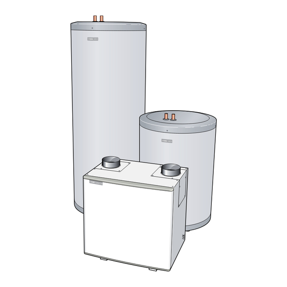
For Home Owners General Principle of operation FIGHTER 120 is a two piece heat pump that is supplied The refrigerant is then compressed in a compressor, with an air treatment section and a stainless-steel stor- causing the temperature to rise considerably. -
Page 6: System Diagram
The hot room air is fed to FIGHTER 120. FIGHTER 120 supplies the Outdoor air is drawn house with hot water. into the house. NIBE FIGHTER 120... -
Page 7: Front Panel
Green Orange Flashing orange Flashing red Heat pump off – Compressor is Defrosting in progress Alarm operational. Heat pump off Periodic hot – Service menus – water increase activated activated* * Fulfils requirements for protection against legionella. NIBE FIGHTER 120... -
Page 8: Remote Control
Acknowledge an alarm by switching the current on FIGHTER 120 off and then on. NOTE! Recurring alarms mean that there is a fault in the installation. Contact your installer! -
Page 9: Basic Settings
Hot water production Ventilation There are three different comfort levels that can be The fan speed in FIGHTER 120 can be selected between selected depending on how much water is needed and three preset modes. how hot the water is required to be. Select in menu A change of fan speed can be made using the remote ”SETTINGS”... -
Page 10: Maintenance Routines
(74) on the hot water heater can be any dirt. Check that the filter is not damaged. New released carefully. original filters can be ordered from NIBE. Carry out assembly in reverse order. The cleaning time intervals vary depending on the amount of dust in the exhaust air. -
Page 11: Dealing With Malfunctions
Upper hot water sensor (87) has been above 95 ˚C. Automatically inactive Contact installer. when the sensor falls below 92 ˚C. FILTER Replace or clean air filter. Indication occurs 90 days (default value) after ack- Replace/clean air filter. nowledging the last filter alarm. NIBE FIGHTER 120... -
Page 12: For The Installer
When FIGHTER 120 circulates and heats up fresh water, calcium and other minerals can affect the components’ (condenser, valves and circulation pump) cleaning cycle/ service life. If FIGHTER 120 is installed in calcium hard water areas, some form of descaler should be installed in the system. -
Page 13: Pipe Installation
Connect the incoming cold water to the T-coupling. backwards) is 15 m. Straight couplings, 22/15 mm, are installed on con- The pressure vessel in FIGHTER 120 is approved for nections (74) and (75) as illustrated. max 9.0 bar (0.9 MPa). -
Page 14: Filling The Hot Water Heater
This is especially important if there are exhaust air devices in bedrooms. not be moved to position 1 until FIGHTER 120 is connected so that all ventilation air the water heater has been filled. except the kitchen fan passes the evaporator (62) in the Otherwise there is a risk of damag- heat pump. -
Page 15: Electrical Connections
Connect the pump in the supplied connector (105), which is connected to FIGHTER 120. The connector must be installed in close proximity to FIGHTER 120. Connect according to the colour codes on ”Top sensor 1” ”Bottom sensor 2”... -
Page 16: Commissioning And Adjusting
If ”PUMP SPD” is greater than 20 % the valve should be opened further. Open the valve in increments of 1/8 of a turn, wait 5 minutes and read off the menus as above. Repeat until the conditions above are fulfilled. NIBE FIGHTER 120... -
Page 17: Service Menus
The ”SETTINGS” > ”LEGIO” > ”LEG.INTV” menu in- dicates how often the increase is to be activated. The interval is adjustable between 1 and 30 days. The func- tion can also be deselected by selecting AV. The factory setting is 14 days. NIBE FIGHTER 120... -
Page 18: Adjusting The Ventilation Flow
Minimum flow should conform to the demands as set out in applicable norms. For optimum fan operation the ventilation flow must not fall below 75 m /h (20 l/s). Fan diagram The diagram below shows the available ventilation capacity. 100% 100% NIBE FIGHTER 120... -
Page 19: Miscellaneous Control
5 seconds. The service menus are now activated. COMFORT The service menus are deactivated automatically after LANGUAGE 10 minutes of inactivity, or manually by repeating the procedure for activation. HEATPUMP MENU UP MAX HW T DIFF RESTART MENU UP NIBE FIGHTER 120... - Page 20 4 °C RESTART 1 – 30 minutes 12 min MENU UP DEFROST MENU UP DEF.TIME 10 – 60 minutes 30 min LOW/MED/HIGH MENU UP LEGIO MENU UP LEG.INTV OFF / 1 – 30 days 7 days MENU UP NIBE FIGHTER 120...
- Page 21 (DEF.TIME) has been exceeded and the evaporation temperature is above 7 °C. Defrosting time. Fan speed during defrost. How often the periodic hot water increase (legionella protection) is to be activated is set here. NIBE FIGHTER 120...
- Page 22 MENU UP SEARCH – – MENU UP MENU UP ALARM MENU UP ALARM – – ALARMLOG MENU UP AL1:5 – – AL2:5 – – AL3:5 – – AL4:5 – – AL5:5 – – MENU UP MENU UP NIBE FIGHTER 120...
- Page 23 Pump control parameters. Pump control parameters. Interval between filter change or cleaning. Search of corresponding remote controls. See section ”Commissioning and adjusting” – ”Registering remote control”. Shows the current alarm. The alarm log displays the last five alarms. NIBE FIGHTER 120...
- Page 24 PUMP SPD 0 – 100 % FAN SPD 0 – 100 % MENU UP RUN TIME MENU UP HEATPUMP – – COMPRESS – – PUMP – – MENU UP FILTER MENU UP DUE IN – – MENU UP NIBE FIGHTER 120...
- Page 25 Manual control of compressor. Manual control of fan. Manual control of circulation pump. Pump speed. Fan speed. Total heat pump operation time. Total compressor operation time. Total circulation pump operation time. Remaining time until next filter change/cleaning. NIBE FIGHTER 120...
-
Page 26: Technical Specifications
Miscellaneous Technical specifications Component locations NIBE FIGHTER 120... - Page 27 Connection, return line, blue (Ø15 mm) Connection, flow line, white (Ø15 mm) Connection, cold water, blue (Ø 28 mm) Connection, hot water, red (Ø 22 mm) Connection, flow line from HP, white (Ø 22 mm) Trim valve 75 74 NIBE FIGHTER 120...
-
Page 28: Dimensions And Setting-Out Coordinates
Miscellaneous Technical specifications Dimensions and setting-out coordinates Air treatment section Ø18 Ø15 Measuring principle Compression ring NIBE FIGHTER 120... - Page 29 Miscellaneous Technical specifications Water heater, 150 litres Water heater, 300 litres Ø596 Ø596 NIBE FIGHTER 120...
-
Page 30: Electrical Circuit Diagram
Miscellaneous Technical specifications Electrical circuit diagram NIBE FIGHTER 120... -
Page 31: Enclosed Kits
Part no. 424 716 T-coupling 28/22/15 x1 Internal reducer conex 22/15 x2 Cirkulation pump x1 Part no. 424 674 Part no. 024 296 Part no. 624 876 Hose Hose damp Part no. 034 020 Part no. 024 217 NIBE FIGHTER 120... -
Page 32: Technical Specifications
Volume 40 °C hot water** > 90 l 180 l 200 l > 90 l 385 l 425 l * Compression ring coupling for 15 mm copper tube included. ** At 10 °C incoming cold water temperature. NIBE FIGHTER 120... - Page 33 Miscellaneous NIBE FIGHTER 120...
- Page 34 Miscellaneous NIBE FIGHTER 120...
- Page 36 NIBE AB, Jerikoveien 20, 1067 Oslo Tel: 22 90 66 00 Fax: 22 90 66 09 E-mail: info @ nibe . se ww w. nib e-villa varme . no NIBE-BIAWAR Sp. z o. o. Aleja Jana Pawła II 57, 15-703 BIAŁYSTOK Tel: 085 662 84 90 Fax: 085 662 84 14 E-mail: sekretariat @ biaw ar.c om.
Need help?
Do you have a question about the FIGHTER 120 and is the answer not in the manual?
Questions and answers