HP Advanced Docking Station Maintenance And Service Manual
Hide thumbs
Also See for Advanced Docking Station:
- Maintenance and service manual (70 pages) ,
- Maintenance and service manual (69 pages)
Table of Contents
Advertisement
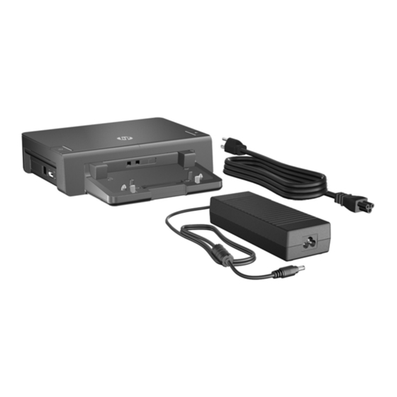
HP Docking Station and HP Advanced Docking Station
Maintenance and Service Guide
Document Part Number: 575274-001
November 2009
This guide is a reference used for maintaining and servicing the docking station. It provides comprehensive
information on identifying docking station features, components, and spare parts; troubleshooting docking station
problems; and performing docking station disassembly procedures.
Advertisement
Table of Contents

Subscribe to Our Youtube Channel
Related Manuals for HP Advanced Docking Station


Summary of Contents for HP Advanced Docking Station
-
Page 1: Maintenance And Service Guide
HP Docking Station and HP Advanced Docking Station Maintenance and Service Guide Document Part Number: 575274-001 November 2009 This guide is a reference used for maintaining and servicing the docking station. It provides comprehensive information on identifying docking station features, components, and spare parts; troubleshooting docking station... - Page 3 © Copyright 2009 Hewlett-Packard Development Company, L.P. The information contained herein is subject to change without notice. The only warranties for HP products and services are set forth in the express warranty statements accompanying such products and services. Nothing herein should be construed as constituting an additional warranty.
- Page 4 Safety warning notice Å WARNING: To reduce the possibility of heat-related injuries or of overheating the computer, do not place the docking station directly on your lap or obstruct the computer air vents. Use the docking station only on a hard, flat surface. Do not allow another hard surface, such as an adjoining optional printer, or a soft surface, such as pillows or rugs or clothing, to block airflow.
-
Page 5: Table Of Contents
Removing the computer from the HP Docking Station ........4–5 Installing the HP Docking Station Lock on the HP Docking Station ......4–6 Installing the HP Docking Station Lock on the HP Advanced Docking Station . - Page 6 Contents 6 Connector pin assignments Audio-in (microphone)..............6–1 Audio-out (headphone) .
-
Page 7: Product Description
■ RJ-45 (network) jack ■ Serial port ■ Smart charging USB 2.0 port ❐ Docking station - 3 USB 2.0 ports ❐ Advanced docking station - 5 USB 2.0 ports Power requirements AC adapter with localized cable plug support Security... - Page 8 Product description HP Docking Station HP Advanced Docking Station 1–2 Maintenance and Service Guide...
-
Page 9: External Component Identification
External component identification External component identification Top components HP Docking Station Item Component Description Power button Turns on power to the computer. ■ On: The computer is on. Power light ■ Off: The computer is off. Visual alignment indicator Helps you correctly align the computer when connecting it to the docking station. -
Page 10: Hp Advanced Docking Station
Align and secure the computer for proper connection to the docking station. Computer eject mechanisms (4) Disconnect the computer from the docking station when you press the eject button. Docking connector Connects the computer to the docking station. HP Advanced Docking Station Item Component Description ■ On: The computer is on. -
Page 11: Front Components
Move inward or outward, adjusting to the size of the battery on the computer so that the computer fits properly into the docking station. Battery lever Moves the battery support posts forward and backward. HP Advanced Docking Station Item Component Description Battery lever Moves the battery support posts forward and backward. -
Page 12: Left-Side Components
This USB port does not turn off when the computer is off or undocked. ✎ HP recommends connecting a hard drive to a USB port that powers off when the computer powers off. HP Advanced Docking Station... -
Page 13: Right-Side Components
This USB port does not turn off when the computer is turned off or is undocked. ✎ HP recommends connecting a hard drive to a USB port that turns off when the computer turns off. Maintenance and Service Guide... -
Page 14: Rear Components
Connects a single-link DVI-D device such as a flat-panel monitor. Powered USB 2.0 port Connects an HP external USB optical drive or hard drive. Other USB hard drives can be connected to this port even when the computer is off or undocked. - Page 15 This USB port does not turn off when the computer is turned off or is undocked. ✎ HP recommends connecting a hard drive to a USB port that turns off when the computer turns off. (18) RJ-45 (network) jack Connects a network cable.
-
Page 16: Hp Advanced Docking Station
DVI ports, both DPs, or a combination of the two ports. Powered USB 2.0 port Connects an HP external USB optical drive or hard drive. Other USB hard drives can be connected to this port even when the computer is off or undocked. - Page 17 This USB port does not turn off when the computer is turned off or is undocked. ✎ HP recommends connecting a hard drive to a USB port that turns off when the computer turns off. (16) Display port 2 The DP connects either an HDMI or DVI device using the appropriate adapter.
-
Page 18: Bottom Components
This dock lock security screw is not included with the unit. It ships with the dock lock kit. When shipped, the screw hole is empty and covered with a rubber insert. Component Description Dock lock security screw Secures the HP Docking Station Lock to the docking station. 2–10 Maintenance and Service Guide... -
Page 19: Illustrated Parts Catalog
Model description: This is the number used to locate documents, drivers, and support for the docking station. ■ Warranty period: Describes the duration of the warranty period for the docking station. Location of service tag on docking station Location of service tag on the advanced docking station Maintenance and Service Guide 3–1... -
Page 20: Major Components
Smart AC Adapter, 90-W, PFC, 3P/RC (HP Docking Station only) 463955-001 Smart AC Adapter, 90-W, PFC, RC/V EM (HP Docking Station only) 535593-001 Smart AC Adapter, 120-W, PFC, 3P/RC (HP Advanced Docking Station only) 463953-001 Smart AC Adapter, 230-W, PFC, RC/V 535592-001... -
Page 21: Sequential Part Number Listing
Illustrated parts catalog Sequential part number listing Spare part number 463953-001 Smart AC adapter, 120-W, PFC, 3P/RC (HP Advanced Docking Station only) 463955-001 Smart AC adapter, 90-W, PFC, 3P/RC (HP Docking Station only) 490371-001 Power cord for use in North America... -
Page 22: Removal And Replacement Procedures
Removal and replacement procedures Removal and replacement procedures Preliminary replacement requirements Tools required You will need the following tools to complete the removal and replacement procedures: ■ Flat-bladed screwdriver ■ Phillips P1 screwdriver Service considerations The following sections include some of the considerations that you must keep in mind during disassembly and assembly procedures. -
Page 23: Grounding Guidelines
Removal and replacement procedures Drive handling Ä CAUTION: Drives are fragile components that must be handled with care. To prevent damage to the computer, damage to a drive, or loss of information, observe these precautions: ■ Before removing or inserting a hard drive, shut down the computer. If you are unsure whether the computer is off or in Hibernation, turn the computer on, and then shut it down through the operating system. - Page 24 Removal and replacement procedures The following table shows how humidity affects the electrostatic voltage levels generated by different activities. Ä CAUTION: A product can be degraded by as little as 700 V. Typical electrostatic voltage levels Relative humidity Event Walking across carpet 35,000 V 15,000 V 7,500 V...
- Page 25 Removal and replacement procedures Equipment guidelines Grounding equipment must include either a wrist strap or a foot strap at a grounded workstation. ■ When seated, wear a wrist strap connected to a grounded system. Wrist straps are flexible straps with a minimum of one megohm ±10% resistance in the ground cords.
-
Page 26: Component Replacement Procedures
Serial number Report the docking station serial number to HP when requesting information or ordering a new unit. The serial number is located on the bottom of the docking station. See “Service tag location”. Removing the computer from the HP Docking Station Perform the following steps to remove the computer from the docking station: 1. -
Page 27: Installing The Hp Docking Station Lock On The Hp Docking Station
The HP Docking Station Lock (purchased separately) allows you to secure the docking station and a docked computer. Loop the cable around a stationary object, connect the security cable to the security cable port on the rear of the docking station, and then install the lock into the lock slot on the right side of the docking station, as shown in the following procedure. - Page 28 Removal and replacement procedures To install the security cable and lock: 1. Loop the cable around a stationary object. 2. Insert the security cable connector into the security cable lock slot at the back of the docking station. 3. Remove the lock bezel blank from the docking station 1. 4.
-
Page 29: Installing The Hp Docking Station Lock On The Hp Advanced Docking Station
The HP Docking Station Lock (purchased separately) allows you to secure the docking station and a docked computer. Loop the cable around a stationary object, then connect the security cable to the security cable port on the rear of the docking station, and then install the lock into the lock slot on the right side of the docking station, as shown in the following procedure. - Page 30 Removal and replacement procedures Lock position Voltage protection level Use this position to install or remove the lock and security cable. In this position, all equipment is unsecured: ■ The key cannot be removed from the lock. ■ The lock can be installed or removed. ■...
- Page 31 Removal and replacement procedures 5. Turn the key to the 1 or 2 position to secure the lock and security cable 3, and then remove the key. The following illustration shows a docking station with the HP Docking Station Lock installed. 4–10...
-
Page 32: Removing A Drive From The Hp Advanced Docking Station Sata Swappable Bay
✎ If you use the HP Docking Station Lock, you must unlock the device before you can remove a drive from the SATA swappable bay. For more information, refer to “Installing the HP Docking Station Lock” in this chapter. -
Page 33: Specifications
Specifications Specifications HP Docking Station specifications Metric U.S. Dimensions Length 16.36 cm 6.44 in Width 26.00 cm 10.24 in Height (front to rear) 6.60 cm 2.60 in Weight 1.07 kg 2.36 lbs Input power Operating voltage 120 to 240 V Operating current 2.5A rms... -
Page 34: Hp Advanced Docking Station Specifications
Specifications HP Advanced Docking Station specifications Metric U.S. Dimensions Length 26.00 cm 10.24 in Width 27.05 cm 10.65 in Height (front to rear) 6.60 cm 2.60 in Weight 1.637 kg 3.61 lbs Input power Operating voltage 120 to 240 V Operating current 2.5A rms... -
Page 35: Connector Pin Assignments
Connector pin assignments Connector pin assignments Audio-in (microphone) Signal Audio signal in Audio signal in Ground Audio-out (headphone) Signal Audio out, left channel Audio out, right channel Ground Maintenance and Service Guide 6–1... -
Page 36: External Monitor
Connector pin assignments External monitor Signal Red analog Green analog Blue analog Not connected Ground Ground analog Ground analog Ground analog +5 VDC Ground Monitor detect DDC 2B data Horizontal sync Vertical sync DDC 2B clock 6–2 Maintenance and Service Guide... -
Page 37: Network)
Connector pin assignments RJ-45 (network) Signal Transmit + Transmit - Receive + Unused Unused Receive - Unused Unused Universal Serial Bus Signal +5 VDC Data Data + Ground Maintenance and Service Guide 6–3... -
Page 38: Power Cord Set Requirements
Power cord set requirements Power cord set requirements The wide range input feature of the docking station permits it to operate from any line voltage from 100 to 120 volts AC or from 220 to 240 volts AC. The 3-conductor power cord set included with the docking station meets the requirements for use in the country or region where the equipment is purchased. -
Page 39: Requirements For Specific Countries And Regions
Power cord set requirements Requirements for specific countries and regions Country/region Accredited agency Applicable note number Australia EANSW Austria Belgium CEBC Canada Denmark DEMKO Finland FIMKO France Germany Italy Japan METI Korea The Netherlands KEMA Norway NEMKO The People's Republic of China Sweden SEMKO Switzerland... - Page 40 Index Index audio-in jack digital video interface (DVI) port connector pinout 6–1 location on advanced docking station 2–8 location on advanced docking station 2–4 location on docking station 2–6 location on docking station 2–6 diskette drive, precautions 4–2 audio-out jack display port connector pinout 6–1...
- Page 41 Index powered USB port location on advanced docking station 2–8 keyboard connector location on docking station 2–6 location on advanced docking station 2–9 product description location on docking station 2–6 features 1–1 notebook compatibility 1–1 left-side components ports 1–1 advanced docking station 2–4 power requirements 1–1...
- Page 42 Index Universal Serial Bus (USB) port, connector pinout 6–3 visual alignment indicator location on advanced docking station 2–2 location on docking station 2–1 Maintenance and Service Guide Index–3...
Need help?
Do you have a question about the Advanced Docking Station and is the answer not in the manual?
Questions and answers