HP Laptop Docking Station Maintenance And Service Manual
Laptop docking station
Hide thumbs
Also See for Laptop Docking Station:
- User manual ,
- Maintenance and service manual (69 pages) ,
- Specification (1 page)
Table of Contents
Advertisement
Maintenance and Service
Guide
HP Docking Station
HP Advanced Docking Station
Document Part Number: 381882-003
May 2007
This guide is a troubleshooting reference used for maintaining
and servicing the HP Docking Station and the HP Advanced
Docking Station. It provides comprehensive information on
identifying docking station features, components, and spare parts;
troubleshooting problems; and performing disassembly
procedures.
Advertisement
Table of Contents
Troubleshooting

Related Manuals for HP Laptop Docking Station


Summary of Contents for HP Laptop Docking Station
-
Page 1: Maintenance And Service
Document Part Number: 381882-003 May 2007 This guide is a troubleshooting reference used for maintaining and servicing the HP Docking Station and the HP Advanced Docking Station. It provides comprehensive information on identifying docking station features, components, and spare parts;... - Page 2 © Copyright 2005–2007 Hewlett-Packard Development Company, L.P. The information contained herein is subject to change without notice. The only warranties for HP products and services are set forth in the express warranty statements accompanying such products and services. Nothing herein should be construed as constituting an additional warranty. HP shall not be liable for technical or editorial errors or omissions contained herein.
-
Page 3: Table Of Contents
1 Product Description 1.1 Features ........1–4 1.2 External Components . -
Page 4: Specifications
Contents 5 Removal and Replacement Procedures 5.1 Serial Number ......5–1 5.2 Preparing the Docking Station for Disassembly . -
Page 5: Product Description
Product Description The HP Docking Station and HP Advanced Docking Station provide desktop convenience with full port replication capability in a space-saving design. The easy docking system provides port replication and cable management in one product. The advanced docking station also provides a MultiBay II slot and an ExpressCard slot. - Page 6 Product Description HP Advanced Docking Station and HP Smart Adapter HP Docking Station and HP Smart Adapter 1–2 Maintenance and Service Guide...
- Page 7 The HP Docking Station and HP Advanced Docking Station are compatible with the following computer models: ■ HP Compaq nc2400 Notebook PC ■ HP Compaq nc4200 and nc4400 Notebook PCs ■ HP Compaq tc4200 and tc4400 Tablet PCs ■ HP Compaq nc6110, nc6120, and nc6140 Notebook PCs ■...
-
Page 8: Features
1.1 Features ■ Integrated cable lock slot ■ Security slot (for standard cable lock) ■ HP Smart Adapter external AC adapter (charges docked PC) ■ Lights (power, docking) ■ Integrated MultiBay II (advanced docking station only) ■ MultiBay II activity light (advanced docking station only) ■... - Page 9 ■ Connectors: ❏ Monitor stand port ❏ External monitor port ❏ Serial port ❏ Parallel port ❏ Keyboard connector ❏ Mouse connector ❏ Audio-out (headphone) jack ❏ Audio-in (microphone) jack ❏ Digital video (DVI) port ❏ Composite video jack ❏ RJ-45/Ethernet (network) jack ❏...
-
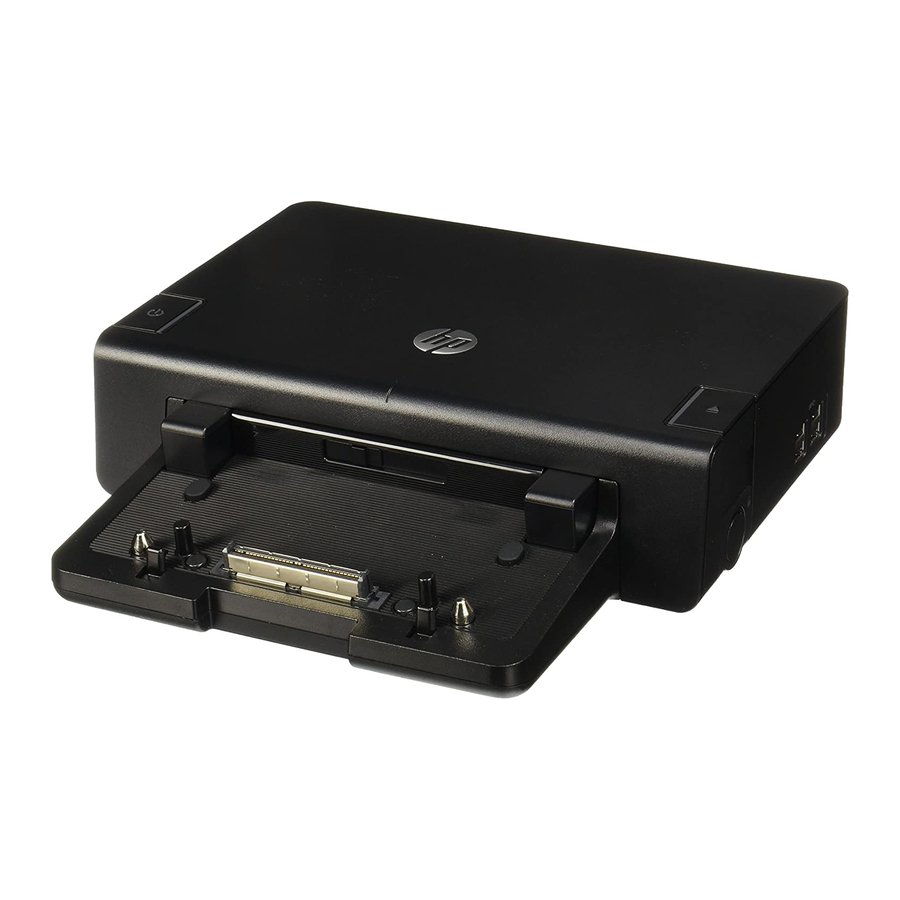
Page 10: External Components
Product Description 1.2 External Components The external components on the top of the docking station are shown in the following illustration and described in Table 1-1. Top Components, Docking Station 1–6 Maintenance and Service Guide... - Page 11 Top Components, Docking Station Item Component Power button Power light Docking posts (2) Computer eject mechanisms (4) Docking connector Visual alignment indicator Computer eject button and docking light Maintenance and Service Guide Table 1-1 Description Turns on power to the computer. Indicates the state of the computer and is turned on when the computer is turned on.
- Page 12 Product Description The external components on the top of the advanced docking station are shown in the following illustration and described in Table 1-2. Top Components, Advanced Docking Station 1–8 Maintenance and Service Guide...
- Page 13 Top Components, Advanced Docking Station Item Component Power button Power light Docking posts (2) Computer eject mechanisms (4) Docking connector Visual alignment indicator Computer eject button and docking light Maintenance and Service Guide Table 1-2 Description Turns on power to the computer. Indicates the state of the computer and is turned on when the computer is turned on.
- Page 14 Product Description The external components on the left side of the docking station are shown in the following illustration and described in Table 1-3. Left-Side Components, Docking Station Left-Side Components, Docking Station Item Component Power button and power light USB port Powered USB port 1–10 Table 1-3...
- Page 15 The external components on the left side of the advanced docking station are shown in the following illustration and described in Table 1-4. Left-Side Components, Advanced Docking Station Left-Side Components, Advanced Docking Station Item Component MultiBay II light MultiBay II USB ports (3) Powered USB port ExpressCard slot...
- Page 16 Product Description The external components on the right side of the docking station are shown in the following illustration and described in Table 1-5. Right-Side Components, Docking Station Right-Side Components, Docking Station Item Component Computer eject button and dock light Integrated cable lock slot 1–12 Table 1-5...
- Page 17 The external components on the right side of the advanced docking station are in the following illustration below and described in Table 1-6. Right-Side Components, Advanced Docking Station Right-Side Components, Advanced Docking Station Item Component Computer eject button and docking light Integrated cable lock slot Supports the cable lock, which secures the Maintenance and Service Guide Table 1-6...
- Page 18 1–14 Table 1-7 Description Connects an optional security cable lock. Connects an optional HP Monitor Stand to the docking station. Connects an audio output device such as headphones or speakers. Connects a PS/2 mouse. Connects a parallel device such as a printer.
- Page 19 AC power. Connects a telephone cable. Connects a network cable. Connect USB devices. Connects the docking station to the HP Smart Adapter AC adapter. Connects a VGA monitor. Connects a serial device such as a mouse. Connects a PS/2 keyboard.
- Page 20 Monitor stand port 1–16 Table 1-8 Description Connects an optional security cable lock. Connects an audio output device such as headphones or speakers. Connects a PS/2 mouse. Connects an optional HP Monitor Stand to the docking station. Maintenance and Service Guide...
- Page 21 Connects a telephone cable. Connects a network cable. Connect USB devices. Connects the docking station to the HP Smart Adapter AC adapter. Connects a VGA monitor. Connects a serial device such as a mouse. Connects a PS/2 keyboard. Connects home audio equipment such as CD and MP3 players.
-
Page 22: Design Overview
Product Description 1.3 Design Overview This section presents a design overview of key parts and features of the HP Docking Station and HP Advanced Docking Station. Refer to Chapter 3, “Illustrated Parts Catalog,” replacement parts, and Procedures,” The docking stations provide the following device connections: ■... -
Page 23: Troubleshooting
WARNING: Only authorized technicians trained by HP should repair Å this equipment. All troubleshooting and repair procedures are detailed to allow only subassembly-/module-level repair. Because of the complexity of the individual boards and subassemblies, do not attempt to make repairs at the component level or modifications to any printed wiring board. -
Page 24: Troubleshooting Checklist
Troubleshooting 2.1 Troubleshooting Checklist When troubleshooting a problem, check the following list for possible solutions before replacing parts: ■ Verify that cables are connected properly to the suspected defective part. ■ Verify that all required device drivers are installed. 2.2 Problems and Solutions The following tables list possible problems, the possible cause of each problem, and the recommended solution. - Page 25 Docking Problems and Solutions (Continued) Problem Some of the ports or connectors do not work, even though the docking light is turned on. Maintenance and Service Guide Possible Cause The computer may be properly aligned, but is not fully seated or docked in the docking station.
- Page 26 Troubleshooting Undocking Problems and Solutions Problem The computer will not disconnect from the docking station. 2–4 Possible Cause The connectors may be jammed. The cable lock is in the locked position. Maintenance and Service Guide Solution Press the eject button all the way in.
-
Page 27: External Device Problems And Solutions
External Device Problems and Solutions Problem A new device is not recognized as part of the system. Maintenance and Service Guide Possible Cause The computer may be properly aligned, but is not fully seated or docked in the docking station. The device cable or power cord is loose. - Page 28 Troubleshooting Optical Drive Problems and Solutions Problem The system cannot read the optical disc. The system cannot eject the media tray. MultiBay II Problems and Solutions Problem The MultiBay II drive is not recognized. 2–6 Possible Cause The disc is not properly seated in the drive tray.
-
Page 29: Illustrated Parts Catalog
Illustrated Parts Catalog This chapter provides an illustrated parts breakdown and a reference for spare part numbers and option part numbers. 3.1 Serial Number Location When ordering parts or requesting information, provide the docking station serial number and model number located on the bottom of the base plate. -
Page 30: Major Components
Illustrated Parts Catalog 3.2 Major Components Major Components, HP Docking Station and HP Advanced Docking Station 3–2 Maintenance and Service Guide... - Page 31 HP Docking Station/HP Advanced Docking Station Item Description HP Docking Station (whole unit replacement) HP Advanced Docking Station (whole unit replacement) Power cord For use in Australia For use in Brazil For use in Denmark For use in Europe, Middle East, and Africa...
-
Page 32: Miscellaneous Spares Kit
Illustrated Parts Catalog 3.3 Miscellaneous Spares Kit Miscellaneous Spares Kit 3–4 Maintenance and Service Guide... - Page 33 Item Description Miscellaneous Plastics Kit, includes: MultiBay II dummy card ExpressCard slot dummy card Large rubber feet, 5 each Small rubber feet, 2 each Rubber bumper (protects unit and computer when docking) Cable lock bezel blank Cable lock bezel Maintenance and Service Guide Table 3-2 Miscellaneous Plastics Kit Illustrated Parts Catalog...
-
Page 34: Sequential Part Number Listing
Power cord for use in Japan Power cord for use in Korea Power cord for use in Switzerland Miscellaneous Plastics Kit AC adapter, 120-W, PFC AC adapter, 135-W, PFC HP Docking Station HP Advanced Docking Station Maintenance and Service Guide... -
Page 35: Removal And Replacement Preliminaries
Removal and Replacement This chapter provides essential information for proper and safe removal and replacement service. 4.1 Tools Required You will need the following tools to complete the removal and replacement procedures: ■ Magnetic screwdriver ■ Phillips P0 screwdriver ■ 5.0-mm hex socket for system board standoffs ■... -
Page 36: Plastic Parts
Removal and Replacement Preliminaries Plastic Parts Using excessive force during disassembly and reassembly can damage plastic parts. Use care when handling the plastic parts. Apply pressure only at the points designated in the maintenance instructions. Cables and Connectors CAUTION: When servicing the expansion base, ensure that cables are Ä... -
Page 37: Packaging And Transporting Precautions
4.4 Packaging and Transporting Precautions Use the following grounding precautions when packaging and transporting equipment: ■ To avoid hand contact, transport products in static-safe containers, such as tubes, bags, or boxes. ■ Protect all electrostatic-sensitive parts and assemblies with conductive or approved containers or packaging. ■... -
Page 38: Workstation Precautions
Removal and Replacement Preliminaries 4.5 Workstation Precautions Use the following grounding precautions at workstations: ■ Cover the workstation with approved static-shielding material (refer to ■ Use a wrist strap connected to a properly grounded work surface and use properly grounded tools and equipment. ■... - Page 39 ■ When standing, use foot straps and a grounded floor mat. Foot straps (heel, toe, or boot straps) can be used at standing workstations and are compatible with most types of shoes or boots. On conductive floors or dissipative floor mats, use foot straps on both feet with a minimum of one megohm resistance between the operator and ground.
- Page 40 Removal and Replacement Preliminaries Table 4-1 shows how humidity affects the electrostatic voltage levels generated by different activities. Typical Electrostatic Voltage Levels Event Walking across carpet Walking across vinyl floor Motions of bench worker Removing DIPS from plastic tube Removing DIPS from vinyl tray Removing DIPS from Styrofoam Removing bubble pack from PCB Packing PCBs in foam-lined box...
-
Page 41: Serial Number
5.1 Serial Number Report the docking station serial number to HP when requesting information or ordering spare parts. The serial number is located on the bottom of the docking station. Serial Number Location Maintenance and Service Guide 5–1... -
Page 42: Preparing The Docking Station For Disassembly
Removal and Replacement Procedures 5.2 Preparing the Docking Station for Disassembly Perform the following steps before disassembling the docking station: 1. If a computer is connected to the docking station, close the computer. If you close the computer with the power turned on, the computer may enter Standby mode. - Page 43 2. Press the eject button 1. The computer disconnects from the docking station. 3. Lift up the computer 2 and set it aside. Undocking the Computer 4. Disconnect all external devices connected to the docking station. 5. Disconnect the power cord from the docking station. Maintenance and Service Guide Removal and Replacement Procedures 5–3...
-
Page 44: Installing The Cable Lock
Removal and Replacement Procedures 5.3 Installing the Cable Lock ✎ Security solutions are designed to act as deterrents. These deterrents may not prevent a product from being mishandled or stolen. The cable lock allows you to secure the docking station and a docked computer, or the advanced docking station with a docked computer and MultiBay II drive installed. - Page 45 To install the cable lock: 1. Loop the cable around a stationary object. 2. Turn the docking station upside down, and then remove the three PM2.5x5 screws from the cable lock bezel 1. 3. Remove the bezel from the docking station 2, and then remove the bezel blank from the cable lock bezel 3.
- Page 46 Removal and Replacement Procedures 4. With the lock and key in the unlocked position and the t-bar on the back of the lock in the vertical position, insert the lock into the center groove in the cable lock slot in the docking station 1.
- Page 47 Removal and Replacement Procedures 6. Turn the key counterclockwise to lock 1. 7. Remove the key from the lock 2. 8. Reinsert the cable lock bezel onto the docking station 3. 9. Replace the screws to secure the bezel 4. Securing the Cable Lock Maintenance and Service Guide 5–7...
- Page 48 Removal and Replacement Procedures The following illustration shows a docking station with the cable lock installed. Docking Station with Cable Lock Inserted 5–8 Maintenance and Service Guide...
-
Page 49: Specifications
This chapter provides physical and performance specifications. HP Docking Station Specifications Dimensions Height Width Length Weight Temperature Operating Nonoperating Relative humidity (noncondensing) Operating Nonoperating Power Supply Rated Voltage Rated Current Line Frequency Maintenance and Service Guide Specifications Table 6-1 28.0 cm 6.1 cm... - Page 50 Specifications HP Docking Station Specifications (Continued) Altitude Operating Non-operating Shock Operating Non-operating Vibration Operating Non-operating 6–2 Table 6-1 0 m to 3,048 m 0 m to 9,144 m 10 G, 11 ms, half-sine 60 G, 11 ms, half-sine 0.5 G zero-to-peak, 10 to 500 Hz, 0.25 oct/min sweep rate 1 G, zero-to-peak, 10 to 500 Hz, 0.5 oct/min...
-
Page 51: Hp Advanced Docking Station Specifications
HP Advanced Docking Station Specifications Dimensions Height Width Length Weight Temperature Operating Nonoperating Relative humidity (noncondensing) Operating Nonoperating Power Supply Rated Voltage Rated Current Line Frequency Maintenance and Service Guide Table 6-2 28.0 cm 6.1 cm 24.3 cm 1.78 kg 10°C to 35°C... - Page 52 Specifications HP Advanced Docking Station Specifications (Continued) Altitude Operating Non-operating Shock Operating Non-operating Vibration Operating Non-operating 6–4 Table 6-2 0 m to 3,048 m 0 m to 9,144 m 10 G, 11 ms, half-sine 60 G, 11 ms, half-sine 0.5 G zero-to-peak, 10 to 500 Hz, 0.25 oct/min sweep rate 1 G, zero-to-peak, 10 to 500 Hz, 0.5 oct/min...
-
Page 53: Screw Listing
Screw Listing This appendix provides specification and reference information for the screws used in the HP Docking Station and the HP Advanced Docking Station. Maintenance and Service Guide A–1... - Page 54 Screw Listing Where used: Three screws that secure the cable lock cover to the base enclosure (documented in Section 5.3) Phillips M2.5×5.0 Screw Locations A–2 Table A-1 Phillips M2.5×5.0 Screw Color Qty. Black Length Thread 5.0 mm 2.5 mm Maintenance and Service Guide Head Width 4.0 mm...
-
Page 55: Connector Pin Assignments
Connector Pin Assignments Signal Audio signal in Audio signal in Maintenance and Service Guide Table B-1 Audio-In (Microphone) Jack Signal Ground B–1... - Page 56 Connector Pin Assignments Audio-Out (Headphone) Jack Signal Audio out, left channel Audio out, right channel B–2 Table B-2 Signal Ground Maintenance and Service Guide...
-
Page 57: External Monitor Port
Signal Red analog Green analog Blue analog Not connected Ground Ground analog Ground analog Ground analog Maintenance and Service Guide Table B-3 External Monitor Port Connector Pin Assignments Signal +5 VDC Ground Monitor detect DDC 2B data Horizontal sync Vertical sync DDC 2B clock B–3... -
Page 58: Keyboard/Mouse Connector
Connector Pin Assignments Keyboard/Mouse Connector Signal Keyboard/mouse DATA Keyboard/mouse DATA Ground B–4 Table B-4 Signal +5 VDC Keyboard/mouse CLK Keyboard/mouse CLK Maintenance and Service Guide... -
Page 59: Parallel Port
Signal Strobe Data bit 0 Data bit 1 Data bit 2 Data bit 3 Data bit 4 Data bit 5 Data bit 6 Data bit 7 Acknowledge Busy Paper end Select Maintenance and Service Guide Connector Pin Assignments Table B-5 Parallel Port Signal Auto linefeed... -
Page 60: Network) Jack
Connector Pin Assignments Signal Unused Ring Signal Transmit + Transmit – Receive + Unused B–6 Table B-6 RJ-11 (Modem) Jack Table B-7 RJ-45 (Network) Jack Signal Unused Unused Unused Signal Unused Receive – Unused Unused Maintenance and Service Guide... -
Page 61: Serial Port
Signal Carrier detect Receive data Transmit data Data terminal ready Ground Maintenance and Service Guide Connector Pin Assignments Table B-8 Serial Port Signal Data set ready Ready to send Clear to send Ring indicator B–7... - Page 62 Connector Pin Assignments Signal TV-Ground TV-CVBS TV-Ground TV-Ground Signal +5 VDC Data – B–8 Table B-9 S-Video-Out Jack Table B-10 Universal Serial Bus Port Signal TV-CD TV-Ground TV-YD Signal Data + Ground Maintenance and Service Guide...
-
Page 63: Power Cord Set Requirements
Power Cord Set Requirements 3-Conductor Power Cord Set The wide range input feature of the docking station permits it to operate from any line voltage from 100 to 120 or 220 to 240 volts AC. The power cord set included with the docking station meets the requirements for use in the country or region where the equipment is purchased. -
Page 64: General Requirements
Power Cord Set Requirements General Requirements The requirements listed below are applicable to all countries or regions. ■ The length of the power cord set must be at least 1.5 m (5.0 ft) and a maximum of 2.0 m (6.5 ft). ■... -
Page 65: Conductor Power Cord Set Requirements
Country/Region Specific Requirements 3-Conductor Power Cord Set Requirements Country/Region Australia Austria Belgium Canada Denmark Finland France Germany Italy Japan ✎ NOTES: 1. The flexible cord must be <HAR> Type HO5VV-F, 3-conductor, 1.0 mm² conductor size. Power cord set fittings (appliance coupler and wall plug) must bear the certification mark of the agency responsible for evaluation in the country or region where it will be used. - Page 66 Power Cord Set Requirements 3-Conductor Power Cord Set Requirements (Continued) Country/Region Korea The Netherlands Norway People’s Republic of China Sweden Switzerland Taiwan United Kingdom United States ✎ NOTES: 1. The flexible cord must be <HAR> Type HO5VV-F, 3-conductor, 1.0 mm² conductor size.
- Page 67 AC adapter, spare part number 3–3 3–6 advanced docking station spare part number 3–3 specifications 6–3 See also docking station audio-in jack location 1–15 pin assignments B–1 audio-out jack location 1–14 pin assignments B–2 bumper, spare part number 3–5 cable lock bezel blank, spare part number 3–5 cable lock bezel, spare part number 3–5...
- Page 68 Index RJ-11 jack B–6 RJ-45 jack B–6 serial port B–7 S-Video-out jack B–8 Universal Serial Bus (USB) port B–8 connectors, service considerations 4–2 design overview 1–18 digital video jack 1–14 disconnection troubleshooting 2–4 2–5 docking connector 1–7 docking light 1–7 docking posts 1–7 docking problems 2–2 docking station...
- Page 69 modem jack location 1–15 pin assignments B–6 monitor port location 1–15 pin assignments B–3 monitor stand port 1–14 mouse connector location 1–14 pin assignments B–4 MultiBay II 1–11 dummy card 3–5 light 1–11 problems 2–6 network jack location 1–15 pin assignments B–6 optical drive problems 2–6 packing precautions 4–3 parallel port...
- Page 70 Index docking station 3–3 Miscellaneous Plastics Kit 3–4 power cord 3–3 specifications advanced docking station 6–3 docking station 6–1 static-shielding materials 4–6 S-Video-out jack location 1–15 pin assignments B–8 tools required 4–1 top components 1–6 transporting precautions 4–3 troubleshooting checklist 2–1 undocking problems 2–4 undocking the computer 5–3 Universal Serial Bus (USB)
Need help?
Do you have a question about the Laptop Docking Station and is the answer not in the manual?
Questions and answers