Table of Contents
Advertisement
Quick Links
Advertisement
Table of Contents

Related Manuals for Icom X BAND 50


Summary of Contents for Icom X BAND 50
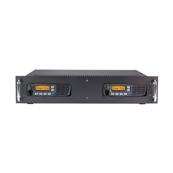
- Page 1 INSTRUCTION MANUAL VHF-UHF FM REPEATER X BAND 50 REPEATER...
-
Page 2: Explicit Definitions
NEVER apply more than 16 V DC, such as a Use Icom microphones only (optional). Other 24 V battery, to the [BATTERY] terminals on the manufacturer’s microphones have different pin repeater rear panel. This could cause a fire or assignments, and connection to the X—Band damage the repeater. series may damage the repeater. NEVER let metal, wire or other objects touch For U.S.A. only any internal part or connectors on the rear panel of the repeater. This may result in an electric CAUTION: This repeater is intended for use as shock. a fixed station with the antenna located outdoors on the rooftop or on antenna tower, or indoors NEVER expose the repeater to rain, snow or with the antenna located near the repeater. any liquids. AVOID using or placing the repeater in areas The Icom America Systems logo is a trademark with temperatures below –30°C (–22°F) or above of Icom, Inc. +60°C (+140°F). Be aware that temperatures on a vehicle’s dashboard can exceed 80°C (+176°F), resulting in permanent damage to the repeater if left there for extended periods. AVOID placing the repeater in excessively dusty environments or in direct sunlight. -
Page 3: Supplied Accessories
FORWARD SUPPLIED ACCESSORIES Thank you for purchasing this Icom America The following accessories are supplied with X—Band 50 series Systems X—BAND 50 VHF/UHF FM REPEATER. With proper care, this product should provide you years of trouble-free operation. [AC120V version] ➀ AC power cable (OPC-510) ….....……… 1 FEATURES Automatic battery backup ❍ charging system A built-in backup system supports automatic switching to an external power supply (13.6 V DC) if the AC power supply fails, and then recharges battery when power is restored. ❍ Multiple CTCSS & DTCS tone memories One CTCSS/DTCS tone (TX/RX tones respectively) can be programmed in a channel. Ideal for many different applications. ❍ Other features - PC programmable - 19 inch rack mount or desktop ❍ Internal controller... -
Page 4: Panel Description
PANEL DESCRIPTION ■ Front Panel ➎ ➊ ➋ ➌ ➍ MICROPHONE/SPEAKER CONNECTOR VOLUME CONTROL [VOLUME] ➊ ➋ [MIC/SP] Adjusts the audio output level. This 8-pin modular jack accepts the optional microphone. DEALER PROGRAMMABLE KEYS ➌ P0, P1, P2, P3 ➀ +8 V DC output (Max. 10 mA) ➁ I/O port for PC programming POWER SWITCH [POWER] ➍ ➂ AFO ➀ ➇ Push to turn the power ON and OFF. ➃ M PTT (Input port for TX control) ➄ Microphone ground INTERNAL SPEAKER ➎ ➅ Microphone input Monitors received signals. -
Page 5: Function Display
PANEL DESCRIPTION 1 ■ Front Panel ➊ ➋ ➏ ➎ ➍ ➌ AF VOLUME CONTROL KNOB DEALER-PROGRAMMABLE KEYS ➊ ➍ [P0] to [P3] Rotate the knob to adjust the audio output level. Desired functions can be programmed independently by your dealer. • Minimum audio level is pre-programmed. FUNCTION DISPLAY ➋ MICROPHONE CONNECTOR ➎ Displays a variety of information, such as an Connect the supplied microphone or optional operating channel number/name. DTMF microphone. NOTE: The above functions depend on pre-programming. CHANNEL CONTROL KEYS ➏... -
Page 6: Ground Terminal [Gnd]
PANEL DESCRIPTION 1 ■ Rear Panel ➏ ➎ ➋ ➍ ➌ ➊ ➐ AC POWER SOCKET [AC] DC POWER INPUT TERMINALS [BATTERY] ➊ ➏ Connects the supplied AC power cable to a Connects the 12 V storage battery for the domestic AC outlet. repeater backup when the AC power is interrupted. These terminals are also used for DC power operation. POWER SWITCH [POWER] ➋ Toggles to turn the repeater power ON or OFF. Located on the back panel of ACCESSORY CONNECTOR [ACC] ➐ the repeater. DB25 connects to the remote controller. -
Page 7: Controller Adjustments
PANEL DESCRIPTION 1 ■ Repeater Controller Programming Both Mobile Radios CS-F3020/F5010/F5020 HANG ON TIME CONFIGURATION JP4 T sec. • Go to LMR>Memory CH>1: Program the TX and RX • Set the CTCSS/CDCSS Tone • Set RF Power to High • LMR > External I/O > Option IGN SW = inhibit Ext. EPTT > Tone Mute EPTT = off Ext. Out (EXO) / Horn > RX EXO = on • LMR External 1/0 > Port Settings EXT. I/O 4 Output Null EXT. I/O 6 Output Null EXT. I/O 7 AFO EXT. I/O 10 Null EXT. I/O 11 Audible EXT. I/O 14 EPTT * Inside the radio, Solder jumper D and solder TX Data wire to F. See fig. 1 and fig. 2. Cut “k”, Solder “I” CABLE CONNECTORS ** 1 = ON; 0 = OFF Accessory Connector Right Radio Accessory Connector Left Radio... - Page 8 Fig. 1 VHF/UHF...
- Page 9 Solder Fig. 2 VHF/UHF...
- Page 10 PANEL DESCRIPTION 1 ■ Accessory connector DB25 Pin Outs Configuration Radio on Right Pin Name Description Specification +15V DC Supply for Internal Device Maximum 1 A DC Ground, UHF Unit Busy Output Terminal for Busy Signal Open Collector+OFF, 0V=ON Audio Output Low Level Audio DISC Discriminator Output Transmit Audio External PTT Active Low Transmit Data Input Radio on Left Pin Name Description Specification +15V DC Supply for External Device Maximum 1A DC Ground Busy Output Terminal for Busy Signal Open...
-
Page 11: Installation And Connections
INSTALLATION AND CONNECTIONS ■ Unpacking ■ Grounding After unpacking, immediately report any damage To prevent electrical shock, television interference to the delivering carrier or dealer. Keep the (TVI), broadcast interference (BCI) and other shipping cartons. problems, ground the transceiver through the [GND] terminal on the rear panel. For a description and a diagram of accessory equipment included with the X-BAND 50 series, For best results, connect a heavy gauge wire or see ‘Supplied accessories’ of this manual. strap to a long earth-sunk copper rod. Make the distance between the [GND] terminal and ground ■ Selecting a location... - Page 12 INSTALLATION AND CONNECTIONS 2 ■ Required Connections [DC POWER INPUT TERMINAL] Make sure the back up battery is correctly connected. Use a cable with following current capacity. Solder or clamp the cable plug when connecting the power cable to the backup battery to prevent voltage drops. Power cable current capacity: 25 A or more TX - RX ANT VHF RX - RX ANT GROUND V HF or UHF TX•RX VHF or UHF TX•RX antenna required. antenna required.
- Page 13 INSTALLATION AND CONNECTIONS 2 ■ Power Make sure the [POWER] switch is turned OFF In DC operation when connecting an AC power cable and a CAUTION: Voltages greater than 16 V DC backup battery (emergency power supply). will damage the repeater. Check the source voltage before connecting the power cable. The X-Band 50 series can operate with an AC or DC power supply. If AC power is interrupted when • DO NOT place the backup battery on or near operating the repeater with an AC power supply, the repeater. Lead-acid batteries should be power is automatically provided to the [BATTERY] placed at least 5 m (16.4 ft.) away from the terminals. Battery will be automatically recharged repeater. Use a heavy duty cable to make when AC power is restored. the connection and be sure both the positive (red) and negative (black) terminals are correctly connected.
-
Page 14: Optional Unit Installation
OPTIONAL UNIT INSTALLATION ■ Opening the repeater’s case Follow the case and cover opening procedures shown here when an optional unit is installed or adjust the internal units, etc. CAUTION: Disconnect the AC power cable and/or DC power cable from the repeater. Otherwise, there is danger of electric shock and/or equipment damage. ➀ Remove 7 screws from the top of the repeater and 1 screw from the top front, then lift up the top cover. -
Page 15: Receiving And Transmitting
LOCAL OPERATION ■ CROSS BAND OPERATION ■ Turning power ON ■ Turning power ON On rear panel, push [POWER] to turn power ➀ On rear panel, push [POWER] to turn power ON. ON. LED will be on if there is AC or DC power in the unit. ■ Receiving and transmitting On each radio, push [POWER] to turn power Receiving on to that radio. ➀ Push [POWER] to turn power ON. Right Radio must be on for Internal Controller ➁ Rotate [VOLUME] to adjust the audio output level. to function. ➂ Push to select the desired channel. • When receiving a signal, BUSY indicator turns ON Push to select the desired channel on each and audio is emitted from the speaker. -
Page 16: Maintenance
MAINTENANCE ■ Fuse replacement If a fuse blows or the repeater stops functioning, try to find the source of the proble, and replace the damaged fuse with a new, rated fuse. Replace the circuitry fuse as shown below. “There are two fuses for each radio The left fuses are for Left Radio The right fuses are for Right Radio WARNING: DISCONNECT the AC power cable and/or DC power cable from the repeater. Otherwise, there is a danger of electric shock and/ or equipment damage. -
Page 17: Specifications And Options
SPECIFICATIONS AND OPTIONS ■ Specifications ◆ X-Band 50 VHF Specification • Frequency coverage 136–174 MHz Wide 16K0F3E (25.0 kHz) • Type of emission Narrow 11K0F3E (12.5 kHz) • Number of programable channels 128 channels (8 zones) • Antenna impedance 50 Ω (nominal) • Operating temperature range –30°C to +60°C (−22°F to +140°F) 13.6 V DC (Negative ground) • Power supply requirement (nominal) Stand-by 300 mA Max.audio 1200 mA • Current drain (approx.) at 25 W 7.0 A at 50 W 14.0 A 480(W) x 133(H) x 364(D) mm; [25 W ver.] 18.90(W) x 5.24(H) x 14.33(D) in • Dimensions (projections not included) 480(W) x 133(H) x 364(D) mm;... - Page 18 SPECIFICATIONS AND OPTIONS 6 ◆ X-Band 50 UHF Specification • Frequency coverage 400–470 MHz 450–512 MHz [USA-01] [USA-02] Wide 16K0F3E (25.0 kHz) • Type of emission 11K0F3E (12.5 kHz) 11K0F7E/D (12.5 kHz)* Narrow 8K10F1E/D (12.5 kHz)* 4K00F1E/D (6.25 kHz)* • Number of programable channels max. 512 channels (128 zones) • Antenna impedance 50 Ω (nominal) • Operating temperature range −30° to +60°; −22°F to +140°F; −22°F to +140°F • Power supply requirement 13.6 V DC (nominal) (nominal) Stand-by 300 mA Max.audio 1200 mA • Current drain (approx.) at 25 W 7.0 A at 50 W 14.0 A 480(W) x 133(H) x 364(D) mm; • Dimensions (projections not included) 18.90(W x 5.24(H) x 14.33(D) in • Weight 8.6 kg (19 lb)
- Page 20 Count on us! ®2012 Icom America Inc. The Icom logo is a registered trademark of Icom Inc. 41052...
Need help?
Do you have a question about the X BAND 50 and is the answer not in the manual?
Questions and answers