Table of Contents
Advertisement
Quick Links
Advertisement
Table of Contents
Troubleshooting

Related Manuals for Whisper Power m-sq25


Summary of Contents for Whisper Power m-sq25
- Page 1 USERS MANUAL M-SQ20 / 25 - 1500 RPM - Marine diesel generating set 230/400V / 50Hz Digital Diesel Control WHISPER POWER BV Kelvinlaan 82 9207 JB Drachten Netherlands Tel.: +31-512-571550 Fax.: +31-512-571599 V1. November 2010 www.whisperpower.eu...
-
Page 2: Table Of Contents
CONTENTS CONTENTS: INTRODUCTION ................................4 General ................................4 Service and maintenance ........................... 4 Guarantee ................................4 Liability ................................5 Identification ............................... 5 1.5.1 General .............................. 5 1.5.2 Identification plate ..........................5 INFORMATION ................................7 Safety ................................. 7 2.1.1 General .............................. 7 2.1.2 Electrical safety .......................... - Page 3 CONTENTS OPERATION .................................. 20 General ................................20 Operating Instructions ............................20 3.2.1 Summarised operating instructions (daily use) ................20 3.2.2 Extended operating instructions ...................... 20 MAINTENANCE ................................23 Alternator ................................23 Engine ................................23 4.2.1 Preliminary instructions ........................23 4.2.2 Bleeding fuel lines ...........................
-
Page 4: Introduction
INTRODUCTION 1 INTRODUCTION General Guarantee This manual applies to the WhisperPower M-SQ20 / 25 WhisperPower guarantees that this generating set has generating set controlled by Digital Diesel Control first been built according to good workmanship, according to launched in September 2005. For other models see other the specifications in this manual and according to manuals available on our website: www.whisperpower.eu. -
Page 5: Liability
INTRODUCTION Identification Example 4: Neglect Whisper generators have an option for an auto start/stop mode or interval mode. 1.5.1 General WhisperPower cannot be held responsible for damage Before using this generating set it is very important to caused by the unattended running generator. identify the set correctly. - Page 6 INTRODUCTION FREQUENCY. This is shown in Hz and is determined by the speed of the engine (RPM). 50 Hz correlates with 1500 rpm. CURRENT. This shows the maximum current that is acceptable at the specified frequency, voltage and power factor. When connected in tri phase the indicated current is the current between two phases that can be taken off three times.
-
Page 7: Information
INFORMATION 2 INFORMATION Safety 2.1.3 Earth insulation failures According to local regulations and depending on the application it could be necessary to take measures for 2.1.1 General protection against earth insulation failures. When correctly installed used normal In the standard delivery “neutral” and “ground” are not circumstances this generating set fulfils EC safety connected. -
Page 8: Operation
INFORMATION 2.1.5 Operation External moving parts like fans and V-belts are covered by the canopy and therefore the M-SQ20 / 25 is very safe when the canopy is closed. BREAK Nevertheless take note of the signs on the generating set which show symbols in a THROUGH triangle indicating danger. -
Page 9: Transport, Lifting And Storage
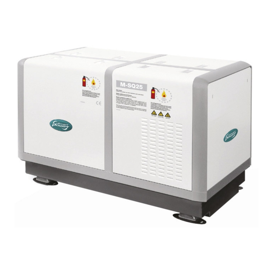
INFORMATION produced which cannot be removed from the The M-SQ20 / 25 skin. If signs of decomposition are evident, or if in doubt, always wear disposable heavy duty 2.3.1 Features gloves. This generating set includes a 4 cylinder diesel engine which is connected by close coupling to a tri phase synchronous alternator in a sound attenuated capsule. -
Page 10: Components
INFORMATION Components 2.4.1 Main components Thermostat housing Boiler connection Engine coolant pump V-belt Exhaust connection Bypass cooling water out Bypass cooling water in Battery + Battery - Fuel out Fuel in Raw water inlet Raw water pump Rubber engine mounting Fig. - Page 11 INFORMATION Hoist eye rear Engine speed adjusting screw Fuel injector Glowplug (4x) Fuel filter Fuses Control panel Air cleaner element Indentification plate Oil swump handpump Coolant drain plug Engine oil dipstick Fuel solenoid Oil filter Injection pump air bleeding screw Fuel lift pump for manual primimg Fuel injection pump...
-
Page 12: Generator Control Panel
INFORMATION 2.4.2 Generator control panel Technical Information 2.5.1 AC alternator The tri phase synchronous alternator is directly coupled, Start / Stop one bearing, brushless, rotating field design, 12 wire, four Internal fuel pump Digital Diesel Control pole (1500 RPM) and regulated by an Automatic Voltage Fuse 3A Fuse 3A Remove fuse... -
Page 13: Engine
INFORMATION 2.5.2 Engine The M-SQ20 / 25 generating set is based on the Mitsubishi S4S 4 cylinder 4 stroke diesel engine. The engine is indirectly injected. The engine is water cooled and the cooling liquid is cooled by a heat exchanger and raw (sea) water. -
Page 14: Control
INFORMATION recommendations. Using wrong 2.5.7 Control The generating set can be operated by push buttons on specification will cause high oil consumption. the panel on the alternator or by the remote control. By pushing the START button the control system is activated Oil viscosity: and will start the engine automatically. -
Page 15: Technical Data
INFORMATION 2.5.14 Technical data GENERAL Model M-SQ20 / 25 1500 rpm Alternator 3 phase synchronous (air cooled) Engine Mitsubishi diesel, model S4S (Japan) Number of cylinders Displacement 3331 cm3 Bore X stroke 94x120 mm Combustion air consumption 10 m³/min. Continuous power 50Hz 25 kW electric power Cooling system indirect cooling by raw water, 20-25 l/min. -
Page 16: Electrical Diagram Control Wiring M-Sq20 / 25
INFORMATION 2.5.15 Electrical diagram control wiring M-SQ20 / 25 Fig. 13 Electrical Diagram control wiring M-SQ20 / 25 November 2010 / M-SQ20 / 25 / EN... -
Page 17: Terminal Modes 115V 400C 50Hz
INFORMATION 2.5.16 Terminal modes 115VAC – 230VAC - 400VAC 50H Fig. 14 Terminal modes EN / M-SQ20 / 25 / November 2010... -
Page 18: Generator Diagram 3 Phase With Avr 230V - 400V 50Hz With Avr
INFORMATION 2.5.17 Generator Diagram 3 phase with AVR 230V – 400V 50Hz with AVR * TO CONNECT NEUTRAL TO GROUND REFER TO 2.1.3 USER MANUAL WHISPER 25U Fig 15. Generator Diagram 3 phase with AVR 230V – 400V 50Hz with AVR November 2010 / M-SQ20 / 25 / EN... -
Page 19: Ac Wiring Diagram Single Phase With Avr 230V Hz (Double Delta)
INFORMATION 2.5.18 AC Wiring Diagram single phase with AVR 230V Hz (Double Delta) * TO CONNECT NEUTRAL TO GROUND REFER TO 2.1.3 USER MANUAL WHISPER 25U Fig 16. AC Wiring Diagram single phase with AVR 230V Hz (Double Delta) EN / M-SQ20 / 25 / November 2010... -
Page 20: Operation
OPERATION 3 OPERATION In operation checks: General Check for abnormal noise or vibration The generating set is operational after full installation and Check the voltage filling up with: fuel, engine lubricating oil and cooling liquid, Check sea water flow at exhaust outlet filling the starter battery with acid (WhisperPower batteries Power source... - Page 21 OPERATION Check sea water cocks. Do not forget the valve of the Power source selector switch (off/shore water outlet in case of a water/exhaust gas separator. power/generator power). Switch to power source Check the water strainer. generator. If a Masterswitch is installed, this operates Check for leakages.
- Page 22 OPERATION Stopping the generating set: Avoid stopping of the generator abruptly after a long period of operation at high load! Doing so, you avoid unnecessary thermal load to your generating set! Act as follows: Prior to switching off the generating set, decrease the generator load (i.e.
-
Page 23: Maintenance
MAINTENANCE 4 MAINTENANCE Alternator The alternator does not require any maintenance. Periodic inspection and cleaning is recommended, depending on environmental conditions. However when the alternator has been idle for a long period attention to winding condition is recommended. condition windings assessed measurement of insulation resistance to earth. -
Page 24: Replacing Oil Filter
MAINTENANCE 4.2.5 Replacing oil filter Replacement has to be executed according to the schedule in this manual. Drain the oil using the sump pump and put some tissues under the filter. Fig. 21 Location rubber packing-ring oil filter. A smear of oil has to be put on the seal of the filter before fitting the filter. -
Page 25: Regular Maintenance
MAINTENANCE Regular maintenance EVERY 150 HOURS: • Change oil. • Check battery acid level (not CHECK DAILY: WhisperPower batteries). • Oil level • Check battery terminals for corrosion Take care the oil level is never below the mark. Do not add •... -
Page 26: Maintenance Schedule
MAINTENANCE 4.3.1 Maintenance schedule 4.3.2 Taking out of service When not using the generating set for a longer period it is recommended execute engine preservation Check oil level daily procedure. Check water inlet filter daily Check the level of the cooling liquid daily Clean the engine. -
Page 27: Trouble Shooting
TROUBLE SHOOTING 5 TROUBLE SHOOTING the possibility to carry out measurements to investigate the Alternator/ electrical faults cause of the failure. Check if the engine is running correctly at 1500 RPM (50 CAUTION! Hz) according to its settings and does as well under load. Remove 3 Amp. -
Page 28: Engine Faults
TROUBLE SHOOTING PROBLEM CAUSE SOLUTION • Rotor diode broken. Check the diode in the rotor (see special procedures). The M-SQ20 / 25 has one diode block/rectifier unit. Generator output voltage too • Engine is not reaching the rated RPM. See special procedures to readjust RPM. low when no load is on it (less than 225V between phase and •... -
Page 29: Trouble Shooting Table
TROUBLE SHOOTING When the engine is cranking, well starting problems bring severe damage to the engine. When the almost always originate from lack of fuel or air bubbles in engine does not start and repeated cranking the fuel pipes. is necessary shut off the seawater inlet. Open the valve immediately after the engine has started. - Page 30 TROUBLE SHOOTING PROBLEM CAUSE SOLUTION • Wrong valve clearance. Adjust valve clearance, • Low compression because of dirty Clean valves. Take off the injection bent and inspect the outlet port. When little rust in the valves. port clean the valve by taking off the valve spring and rotate until clean.
- Page 31 TROUBLE SHOOTING PROBLEM CAUSE SOLUTION Engine starts, but stops after 10 • Protection system stops the engine; See paragraph 2.5.5. and 3.2.2 for information seconds on the alarm system. Bypassing the switches this can be caused by oil pressure can help to confirm the failure. When there is failure, lack of cooling water (exhaust no real failure, it could be a faulty alarm switch temperature alarm).
-
Page 32: Warnings
TROUBLE SHOOTING the bottom speed protection should first be calibrated. The Warnings voltage reference (orange wires) should be connected: • to terminals “0” and “115” for an output voltage CAUTION! Generator must be shut off immediately if: between 100 and 140V (factory setting) •... -
Page 33: Residual Voltage Check / Excitation Procedure (Flashing)
TROUBLE SHOOTING rectifier unit. One can get access to the diode unit by 5.3.2 Residual voltage check / excitation taking off the backend of the alternator. procedure (flashing) When residual magnetism disappears there is no residual voltage. Residual magnetism can disappear after the generating set being out of service for a long period or a short circuit. -
Page 34: Meggering
TROUBLE SHOOTING 5.3.5 Meggering One can try to measure resistance between the housing and the windings with a multimeter which should read infinity. When readings are infinity but a fault is suspected one can do a high voltage resistance test (MEGGERING) This procedure should be carried out by an expert. -
Page 35: Adjusting Valve Clearance And Retightening The Cylinder Head Bolts
TROUBLE SHOOTING 360° in the direction of engine rotation again. No. 1 piston 5.4.2 Adjusting valve clearance and is now at T.D.C. of the compression stroke. retightening the cylinder head bolts. Both procedures have to be executed with a cold engine. After adjusting the valves of cylinder 1 adjust the valve When both procedures are executed be sure to retighten clearance of the remaining cylinders in firing order 1-3-4-2... -
Page 36: Disassembling Instructions
TROUBLE SHOOTING Following instructions will help: 5.4.4 Disassembling instructions It could be necessary for repair or checks to disassemble The design of the M-SQ20 / 25 makes it possible to the generating set. do most repairs on the spot. The heat exchanger is accessible and can be removed. - Page 37 TROUBLE SHOOTING To take the generating set out of the canopy all hose Reassembling the generating set one should take and cable connections have to be taken off. The set is care of alignment, cleaning the surfaces between fixed to its base by four rubber mountings and can be engine and alternator and tighten the bolts crosswise loosened by removing the four nuts from the bolts of and gradually.
-
Page 38: Spare Parts
SPARE PARTS 6 SPARE PARTS A complete parts manual in English is available as an option number: number: 40200187 (***) A work shop manual in English is available as an option, number: 40200174 (***). We recommend the following spares for service and maintenance. •... - Page 39 SPARE PARTS EN / M-SQ20 / 25 / November 2010...
- Page 40 SPARE PARTS November 2010 / M-SQ20 / 25 / EN...
-
Page 41: Maintenance Log
MAINTENANCE LOG MAINTENANCE LOG first service after 50 hours: hour counter: remarks: next service (every 150 hours): hour counter: remarks: EN / M-SQ20 / 25 / November 2010... - Page 42 NOTES NOTES November 2010 / M-SQ20 / 25 / EN...
- Page 43 MAINTENANCE LOG NOTES EN / M-SQ20 / 25 / November 2010...
- Page 44 Kelvinlaan 82, 9207 JB Drachten, Netherlands Tel : + 31-512-571550 / Fax : + 31-512-571599 www.whisperpower.eu / info@whisperpower.nl...
Need help?
Do you have a question about the m-sq25 and is the answer not in the manual?
Questions and answers