
Related Manuals for Danfoss AK-CC 550B


Summary of Contents for Danfoss AK-CC 550B
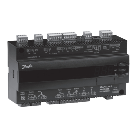
- Page 1 User Guide Controller for appliance control AK-CC 550B ADAP-KOOL® Refrigeration control systems Manual...
-
Page 2: Table Of Contents
LonWorks / DANBUSS communication card Appliance examples Contents Introduction ....................... 2 Operation ......................26 Operation ......................4 Menu survey .....................28 Applications .....................12 Connections .....................32 Survey of functions ..................15 Data ........................34 Ordering ......................35 Manual RS8GL302 © Danfoss 2016-03 AK-CC 550B... -
Page 3: Application 9
There are separate alarm limits and alarm delays for each cooling section. Display for each section. Software opdatering AK-CC 550B was updated at the end of 2012 to software version 1.6. The update applies primarily to applications 6, 9 and 10. The previous version (software version 1.2) is described in... -
Page 4: Operation
Minimum and maximum limits can be set for alarm temperature and time delays. A longer time delay can be set for high temperature alarms. This delay is active after defrosting, appliance cleaning, appliance shutdown and start-up. Manual RS8GL302 © Danfoss 2016-03 AK-CC 550B... - Page 5 The cooling appliance is stopped like the “Main switch”, but this happens without an “A45 standby alarm”. The function can be enabled by a switch on the DI input or via a setting through data communication. AK-CC 550B Manual RS8GL302 © Danfoss 2016-03...
- Page 6 All the mentioned methods can be used at random – if just of them is activated a defrost will be started. Stop of defrost Defrosting can be stopped by either: • Time • Temperature (with time as safety). Manual RS8GL302 © Danfoss 2016-03 AK-CC 550B...
- Page 7 The refrigeration will then be stopped during the set melting period. The frost will be melted so that the air flow and hence the evaporator’s capacity will be greatly improved. AK-CC 550B Manual RS8GL302 © Danfoss 2016-03...
- Page 8 In the area between the two dew point values the controller will manage the power to be supplied to the rail heat. Dew point During defrosting During defrosting the rail heat will always be 100% ON. Manual RS8GL302 © Danfoss 2016-03 AK-CC 550B...
- Page 9 A night blind is open when the appliance cleaning function is activated. A setting can define that the night blind is open when "r12" (Main switch) is set to off (see o98). AK-CC 550B Manual RS8GL302 © Danfoss 2016-03...
- Page 10 To prevent that the heating thermostat cuts in during short-term drops in air temperature a Heat time delay can be set for when to change from refrigeration to heating. Manual RS8GL302 © Danfoss 2016-03 AK-CC 550B...
- Page 11 The controller contains a number of functions which can be used together with the override function in the master gateway/system manager. Function via data communication Function in gateway/system manager Used parameters in AK-CC 550B Start of defrosting Defrost control / Time schedule / Defrost group --- Def start...
-
Page 12: Application
Application 1-4 Standard applications. This is for standard use where the vital difference is only different combinations of the following functions/outputs: • Alarm • Rail heat • Compressor • Light Manual RS8GL302 © Danfoss 2016-03 AK-CC 550B... -
Page 13: This Application Is For Refrigeration Appliances With
This application is for refrigeration appliances with one valve, one evaporator and two refrigeration sections. Alarm monitoring and display readings take place individually via the "S3" sensors in each refrigeration section. Separate product sensor can be connected. AK-CC 550B Manual RS8GL302 © Danfoss 2016-03... -
Page 14: Application 1
The number is indicated on the left-hand side of the signs. Use the sign with the current application number. One of the signs applies to both applications 4 and 10. Manual RS8GL302 © Danfoss 2016-03 AK-CC 550B... - Page 15 Here you define the sensor the thermostat is to use for its control function. S3, S4, or a combination of them. With the setting 0%, only S3 is used (Sin). With 100%, only S4. AK-CC 550B Manual RS8GL302 © Danfoss 2016-03...
- Page 16 (Alarms will not activate when the setting is set to the maximum value.) Delay of a DI1 alarm AI.Delay DI1 A cut-out/cut-in input will result in alarm when the time delay has been passed. The function is defined in o02. Manual RS8GL302 © Danfoss 2016-03 AK-CC 550B...
- Page 17 2 = Gas Defrost stop temperature Def. Stop Temp The defrost is stopped at a given temperature which is measured with a sensor (the sen- sor is defined in d10). The temperature value is set. AK-CC 550B Manual RS8GL302 © Danfoss 2016-03...
- Page 18 4: All schedules are carried out + extra if it is registered that it is required. (Reset: Temporary setting to 0 will reset the recorded values and start a new calculation of the evaporator air flow.) Manual RS8GL302 © Danfoss 2016-03 AK-CC 550B...
- Page 19 In the event of a power failure of less than four hours, the clock function will be saved. Clock: Hour setting Clock: Minute setting Clock: Date setting Clock: Month setting Clock: Year setting AK-CC 550B Manual RS8GL302 © Danfoss 2016-03...
- Page 20 Warning: Wrong selection of refrigerant may cause damage to the compressor. Other refrigerants: Here Setting 13 is selected and then three factors -Ref.Fac a1, a2 and a3 - via AKM must be set. Manual RS8GL302 © Danfoss 2016-03 AK-CC 550B...
- Page 21 1 (o05) must also be used. Save as factory setting With this setting you save the controller’s actual settings as a new basic setting (the earlier factory settings are overwritten). AK-CC 550B Manual RS8GL302 © Danfoss 2016-03...
- Page 22 The groups that are to activate the alarm relay must be set by using a numerical value which is the sum of the groups that must be activated. (E.g.: a value of 5 will activate all high temperature alarms and all sensor error. 0 will cancel the relay function) Manual RS8GL302 © Danfoss 2016-03 AK-CC 550B...
- Page 23 Measured temperature for alarm thermostat for B section Display air B Air temperature. Weighted S3 + S4 temp. for B section *) Not all will be displayed. Only the function belonging to the selection application is displayed. AK-CC 550B Manual RS8GL302 © Danfoss 2016-03...
- Page 24 *) Emergency cooling will take effect when there is lack of signal from a defined S3 or S4 sensor. The regulation will continue with a registered average cutin frequency. There are two registered values – one for day operation and one for night operation. Manual RS8GL302 © Danfoss 2016-03 AK-CC 550B...
- Page 25 The importance of individual alarms can be defined with a setting. The setting must be carried out in the group "Alarm destinations" Settings from Settings from Alarm relay Send via High Low-High System manager AKM (AKM destination) Network High Middle Log only Disabled AK-CC 550B Manual RS8GL302 © Danfoss 2016-03...
-
Page 26: Operation
Reading the temperature at defrost sensor (Or product sensor, if selected in o92.) • A short press of the lower button Manuel start or stop of a defrost • Push the lower button for four seconds. Manual RS8GL302 © Danfoss 2016-03 AK-CC 550B... - Page 27 Sensor signal for alarm funct.S4% (A36) 100% Interval between defrost (d03) Defrost sensor: 0=time, 1=S5, 2=S4 (d10) DI1 config. (o02) Case cleaning (=10) Door function (=2) Sensor signal for display view S4% (017) AK-CC 550B Manual RS8GL302 © Danfoss 2016-03...
-
Page 28: Menu Survey
Displacement of time on cutin of defrost at start-up 0 min. 240 min. Drip off time 0 min. 60 min. Delay for fan start after defrost 0 min. 60 min. Fan start temperature -50 °C 0 °C Manual RS8GL302 © Danfoss 2016-03 AK-CC 550B... - Page 29 7=R13b1. 8=R23. 9=R500. 10=R503. 11=R114. 12=R142b. 13= 14=R32. 15=R227. User defined. 16=R401A. 17=R507. 18=R402A. 19=R404A. 20=R407C. 21=R407A. 22=R407B. 23=R410A. 24=R170. 25=R290. 26=R600. 27=R600a. 28=R744. 29=R1270. 30=R417A. 31=R422A. 32=R413A. 33=R422D. 34=R427A. 35=R438A. 36=R513A. 37=R407F. AK-CC 550B Manual RS8GL302 © Danfoss 2016-03...
- Page 30 The groups that are to activate the alarm relay must be set by using a numerical value which is the sum of the groups that must be activated. (E.g.: a value of 5 will activate all high temperature alarms and all sensor error. Manual RS8GL302 © Danfoss 2016-03 AK-CC 550B...
- Page 31 If you need to return to the factory-set values, it can be done in this way: - Cut out the supply voltage to the controller - Keep upper and lower button depressed at the same time as you reconnect the supply voltage AK-CC 550B Manual RS8GL302 © Danfoss 2016-03...
-
Page 32: Applications
S5, defrost sensor, placed on the evaporator be a 230 V a.c. coil. S6, product sensor. EKA Display If there is be external reading/operation of the controller, display type EKA 163B or EKA 164B can be connected. Manual RS8GL302 © Danfoss 2016-03 AK-CC 550B... - Page 33 Electronic controls are no substitute for normal, good engineering practice. Danfoss will not be responsible for any goods, or plant compo- There is connection between terminal 15 and 16 when the fan nents, damaged as a result of the above defects. It is the installer's is on.
-
Page 34: Data
The relays cannot be used for the direct connection of capacitive loads such as LEDs and on/off control of EC motors. All loads with a switch mode power supply must be connected with a suit- able contactor or similar. Manual RS8GL302 © Danfoss 2016-03 AK-CC 550B... -
Page 35: Ordering
084B7299 (Cable, 6 m) LON / DANBUSS 084B8032 084B8574 (Display) 084B7299 (Cable, 6 m) 084Bxxxx (Data module) L < 15 m MODBUS / LON / DANBUSS 084B8032 084B8562 (Display) 084Bxxxx (Data module) L > 15 m AK-CC 550B Manual RS8GL302 © Danfoss 2016-03... - Page 36 Danfoss can accept no responsibility for possible errors in catalogues, brochures and other printed material. Danfoss reserves the right to alter its products without notice. This also applies to products already on order provided that such alternations can be made without subsequential changes being necessary in specifications already agreed.
Need help?
Do you have a question about the AK-CC 550B and is the answer not in the manual?
Questions and answers