Danfoss 51 Series Service Manual
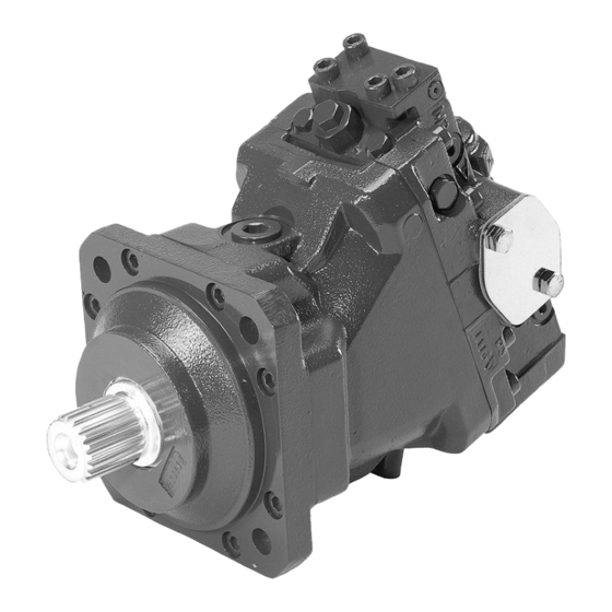
Bent axis motors two position controls
Hide thumbs
Also See for 51 Series:
- Service manual (64 pages) ,
- Repair instructions (36 pages) ,
- Service kit instructions (2 pages)

Subscribe to Our Youtube Channel
Related Manuals for Danfoss 51 Series


Summary of Contents for Danfoss 51 Series
- Page 1 MAKING MODERN LIVING POSSIBLE Service Manual Bent Axis Motors Series 51 Two Position Controls powersolutions.danfoss.com...
- Page 2 Service Manual Series 51 Two Position Controls Service Manual Revision history Table of revisions Date Changed January 2015 Danfoss layout March 2009 Added TA, TH, TN, PC, PD February 2008 First edition 11009442 • Rev CA • January 2015...
-
Page 3: Table Of Contents
Safety Precautions....................................5 Unintended Machine Movement............................5 Flammable Cleaning Solvents..............................5 Fluid Under Pressure..................................5 Personal Safety.....................................5 Hazardous Material..................................5 Symbols used in Danfoss literature............................6 Overview......................................7 General instructions..................................7 Keep it Clean....................................7 Inspect for System Contamination............................7 Replace the O-rings and Gaskets............................7 Lubricate all Moving Parts................................7 Torque Procedure.................................. - Page 4 Service Manual Series 51 Two Position Controls Service Manual Contents Repair........................................25 Removing Solenoid(s)................................25 T1/T2/T3/T4 controls................................25 Disassembly....................................25 T1/T2/T3/T4/TA/TH/TM/TN controls..........................25 Inspection....................................27 Assembly......................................27 Solenoid Assembly...................................28 T1/T2/T3/T4 controls................................28 N2 Controls Operation......................................29 Functional Description................................29 Repair........................................29 Disassembly....................................29 Inspection....................................30 Assembly......................................30 E1, E2, F1, F2 Controls Operation......................................32 Functional Description................................
-
Page 5: Safety Precautions
Service Manual Series 51 Two Position Controls Service Manual Introduction Safety Precautions Always consider safety precautions before beginning a service procedure. Protect yourself and others from injury. Take the following general precautions whenever servicing a hydraulic system. Unintended Machine Movement Warning Unintended movement of the machine or mechanism may cause injury to the technician or bystanders. -
Page 6: Symbols Used In Danfoss Literature
Service Manual Series 51 Two Position Controls Service Manual Introduction Symbols used in Danfoss literature WARNING may result in injury Tip, helpful suggestion CAUTION may result in damage to product or Lubricate with hydraulic fluid property Reusable part Apply grease / petroleum jelly... -
Page 7: Overview
Service Manual Series 51 Two Position Controls Service Manual Introduction Overview This manual includes information for the installation, maintenance, and minor repair of Series 51 two- position controls. It includes a description of each control, instructions for adjustment, and minor repair procedures. -
Page 8: Operation
Service Manual Series 51 Two Position Controls Service Manual Operation Two-position Controls Two-position controls shift the motor to either maximum or minimum displacement. Control input may be hydraulic or electric. To change displacement, the control routes pilot pressure to one end of the servo piston while draining the other. -
Page 9: Brake Pressure Defeat (Bpd)
Service Manual Series 51 Two Position Controls Service Manual Operation The PCOR setting pressure is adjustable from 130 to 370 bar [1890 to 5370 psi]. Optional orifices at locations T4, T5, T6, U6, or U7 regulate the speed of the PCOR operation. PCOR option P101 906 Example of T* PCOR option... - Page 10 Service Manual Series 51 Two Position Controls Service Manual Operation EP, EQ electrohydraulic proportional control with pressure compensator and hydraulic brake pressure defeat. Shuttle Loop flushing Max. displ. PCOR Multifunction Block P101 907 Control BPD option Brake defeat spool Shuttle valve PCOR adjuster PCOR spool P106 431E...
-
Page 11: Threshold Spring
Service Manual Series 51 Two Position Controls Service Manual Operation Threshold Spring A threshold spring acts on the opposite end of the 4-way valve. Adjusting the threshold screw changes the pressure required to move the 4-way valve and start the change in displacement. Optional orifices may be installed at several locations to regulate shift speed. - Page 12 Service Manual Series 51 Two Position Controls Service Manual Operation resolves high pressure for servo supply and low pressure for control pilot also feeds these pressures to an optional Pressure Compensating Over-Ride (PCOR) valve. Multifunction block schematic Loop flush Shuttle max.
-
Page 13: Pressure Measurements
Service Manual Series 51 Two Position Controls Service Manual Pressure measurements Port Locations and Gauge Installation Series 51 motors Main ports A+B side port P101 204E Axial port System pressure A+B Guage port M1+M2 Main port B Axial port Main port A P101 204E Legend... - Page 14 Service Manual Series 51 Two Position Controls Service Manual Pressure measurements G1, G2 controls Shaft center Solenoid wiring DIN connector 43650-AM2 Charge pressure relief valve P106 392E Legend Abbreviation Definition Gauge port: servo pressure max. angle (9/16-18UNF) E1/E2, F1/F2. H1/H2, and K1/K2 controls P106 393E 11009442 •...
- Page 15 Service Manual Series 51 Two Position Controls Service Manual Pressure measurements Gauge ports with U1/U2 controls and T1, T2, T3, T4, TA, and TH controls Solenoid for electric 2 position control P106 395E Legend Abbreviation Definition M7, M8 Gauge port control pressure (9/16-18UNF) X (A, B, and 1) Control pressure port (9/16-18UNF) 11009442 •...
-
Page 16: Adjustments
Service Manual Series 51 Two Position Controls Service Manual Adjustments Threshold Setting Adjusting Threshold Setting Threshold on two-position controls is 3 bar [44 psi], except on T* controls. 1. Using a 10 mm wrench loosen the locknut on the adjustment screw. 2. -
Page 17: Checking Pcor Setting On A Test Stand
Service Manual Series 51 Two Position Controls Service Manual Adjustments 2. Install a 600 bar [10000 psi] gauge at port M3 to read minimum servo pressure. 3. Safely prevent the motor shaft from moving by: • applying the park brake, apply an extreme load, or •... -
Page 18: Pressure Compensator Override (Pcor)
Service Manual Series 51 Two Position Controls Service Manual Pressure Compensator Override (PCOR) Repair Disassembly 1. Remove plugs (N27). Remove and discard O-rings (N27A). 2. Using a 1 inch hex wrench, remove plug (N23). Remove and discard O-ring (N23A). 3. Remove locknut (N14). 4. - Page 19 Service Manual Series 51 Two Position Controls Service Manual Pressure Compensator Override (PCOR) 4. Lubricate and install spool and spring guide assembly (N20). 5. Install spring (N18) to cavity. 6. Lubricate and install new O-ring (N16J). Install adjustment plug (Z00). 7.
-
Page 20: Multifunction Block
Service Manual Series 51 Two Position Controls Service Manual Multifunction Block Repair Disassembly 1. Using a ¼ inch internal hex wrench, remove plugs (N26). Remove and discard O-rings (N26A). 2. Remove the double resolver spool (N30). 3. Using a 1/8 inch internal hex wrench, remove plugs (N27). Remove and discard O-rings (N27A). 4. -
Page 21: Inspection
Service Manual Series 51 Two Position Controls Service Manual Multifunction Block Tool size and torque (continued) Item Wrench size Torque 10 mm internal hex 110 N•m [81 lbf•ft] (160, 250) Inspection Clean and inspect components for damage or foreign material. Replace damaged parts. Assembly 1. -
Page 22: T1, T2, T3, T4, Ta, Th, Tm, Tn
Service Manual Series 51 Two Position Controls Service Manual T1, T2, T3, T4, TA, TH, TM, TN Operation TA Control The TA control does not have two-position operation, it is Pressure Compensating Over-Ride (PCOR) operation only. It uses a sensing piston (M12) to shift the 4-way valve when system pressure reaches the PCOR setting. -
Page 23: C2/C4
Service Manual Series 51 Two Position Controls Service Manual T1, T2, T3, T4, TA, TH, TM, TN C2/C4 The C2 or C4 order ode uses no BPD option: PCOR function operates when either system pressure is high. The BPD spool resolves high pressure and routes it to the 4-way valve for servo supply and to the sensing piston. - Page 24 Service Manual Series 51 Two Position Controls Service Manual T1, T2, T3, T4, TA, TH, TM, TN TA schematic max. disp. T7 T8 M5(X3) TA - R5/R6 TA - L5/L6 TA - C2/C4 TA - C0/C3 P106 360E TH schematic max.
-
Page 25: Repair
Service Manual Series 51 Two Position Controls Service Manual T1, T2, T3, T4, TA, TH, TM, TN TM/TN schematic max. disp. T7 T8 M5(X3) TM-E 7 (12V) TM-F 7 (12V) P107 827E TN-F 8 (24V) TN-E 8 (24V) Repair Removing Solenoid(s) T1/T2/T3/T4 controls Solenoid(s) (M1) available as complete assembly only. - Page 26 Service Manual Series 51 Two Position Controls Service Manual T1, T2, T3, T4, TA, TH, TM, TN 11. Remove piston (M12). Module disassembly J10* F324 G420 (TM, TN) (may be on either side of spool) (used with TM, TN only) E*/F* NT41 L5/L6, R5/R6...
-
Page 27: Inspection
Service Manual Series 51 Two Position Controls Service Manual T1, T2, T3, T4, TA, TH, TM, TN Item Wrench size Torque 1/8 internal hex 6 N•m [4.5 lbf•ft] Inspection 1. Clean and inspect the housing and spools for wear, damage or foreign material. 2. -
Page 28: Solenoid Assembly
Service Manual Series 51 Two Position Controls Service Manual T1, T2, T3, T4, TA, TH, TM, TN Solenoid Assembly T1/T2/T3/T4 controls 1. Lubricate and install O-ring (M1A). Install solenoid stem. 2. Using a thin 3/4 inch wrench on the flats provided, torque to 47 N•m [35 lbf•ft]. 3. -
Page 29: N2 Controls
Service Manual Series 51 Two Position Controls Service Manual N2 Controls Operation Functional Description The N2 control consists of a cover plate mounted on the motor’s endcap, a seal plug in place of the four- way valve, and passage plugs at locations T1, T2, and T3. The servo piston is powered externally. -
Page 30: Inspection
Service Manual Series 51 Two Position Controls Service Manual N2 Controls Inspection Clean and inspect components for damage or foreign material. Replace damaged parts as necessary. Assembly 1. Lubricate and install new O-ring (M12) to plug (M10). 2. Install the plug (M10) to the four-way valve cavity in the end cap. 3. - Page 31 Service Manual Series 51 Two Position Controls Service Manual N2 Controls 9. Lubricate and install new O-ring (G12A) onto plug (G12). Using a 1/4 inch internal hex wrench, install plug. Torque to 37 N•m [28 lbf•ft].. N2 Control G30A G12A G30A T2 G420 P101 217E...
-
Page 32: E1, E2, F1, F2 Controls
Service Manual Series 51 Two Position Controls Service Manual E1, E2, F1, F2 Controls Operation Functional Description The E* and F* two-position controls consist of a ported housing containing a cartridge style, 3-way, two- position, solenoid valve. The control housing mounts to the multifunction block containing the double- resolver spool. -
Page 33: Assembly
Service Manual Series 51 Two Position Controls Service Manual E1, E2, F1, F2 Controls 2. Using a ¼ inch internal hex wrench, remove plugs (M22, M19). Remove and discard O-rings (M22A, M19A). 3. Using a 4 mm internal hex wrench, remove screws (M14). 4. - Page 34 Service Manual Series 51 Two Position Controls Service Manual E1, E2, F1, F2 Controls 6. Install the coil nut. Using a 3/4 inch hex wrench, torque to 6 N•m [4 lbf•ft]. Do not overtorque. E*, F* control M22A Cartridge M19A P106 382E Coil Tool sizes and torques...
-
Page 35: Operation
Service Manual Series 51 Two Position Controls Service Manual G1, G2, G7 Operation Functional Description The G* two-position controls consist of a ported housing that contains a four-way, 2-position, solenoid operated cartridge valve. A seal plug is installed in the four-way valve cavity in the motor’s endcap. The control contains a loop-flushing shuttle valve and relief valve. -
Page 36: Disassembly
Service Manual Series 51 Two Position Controls Service Manual G1, G2, G7 G* control G420 F324 G20A M15A M152 M151 G20A M150 M14A P101 212 Tool sizes and torques Item Wrench size Torque 1/8 inch internal hex 9 N•m [7 lbf•ft] 1/4 inch internal hex 37 N•m [28 lbf•ft] 1-1/16 inch hex... -
Page 37: Inspection
Service Manual Series 51 Two Position Controls Service Manual G1, G2, G7 4. Remove two plugs (G20). Remove and discard O-rings (G20A). 5. Remove loop-flushing springs (K14), seats (K16), and spool (K18). 6. Using a 3/4 inch wrench, remove coil nut and coil from solenoid valve (M1). 7. - Page 38 Service Manual Series 51 Two Position Controls Service Manual G1, G2, G7 G* control G420 F324 G20A M15A M152 M151 G20A M150 M14A P101 212 Tool sizes and torques Item Wrench size Torque 1/8 inch internal hex 9 N•m [7 lbf•ft] 1/4 inch internal hex 37 N•m [28 lbf•ft] 1-1/16 inch hex...
-
Page 39: U1, U2
Service Manual Series 51 Two Position Controls Service Manual U1, U2 Operation Functional Description The U* two-position controls consist of a ported housing containing a shuttle spool and a solenoid. The shuttle spool resolves which port, system A or system B, is at higher pressure, routing that high pressure to the four-way valve to power the servo piston. - Page 40 Service Manual Series 51 Two Position Controls Service Manual U1, U2 9. Remove piston (M12). 10. Remove the 4-way valve assembly (F32). Discard O-rings (F324). Caution Read Series 51 and 51-1 Bent Axis Motors Service Manual 11008567 for minor repair instructions for the 4-way valve, threshold spring, and ramp spring components, if repair is necessary.
-
Page 41: Inspection
Service Manual Series 51 Two Position Controls Service Manual U1, U2 Tool size and torque (continued) Item Wrench size Torque 10 mm internal hex 110 N•m [81 lbf•ft] (160, 1250) M16, N20, NT40 1/4 inch internal hex 37 N•m [28 lbf•ft] 3 mm internal hex 1. -
Page 42: Pc, Pd
Service Manual Series 51 Two Position Controls Service Manual PC, PD Operation Functional Description PC Control The PC control consists of a multifunction block with PCOR valve attached. The multifunction block contains the servo supply spool. It resolves high loop pressure for servo supply, and routes the high loop pressure to the PCOR valve. -
Page 43: Repair
Service Manual Series 51 Two Position Controls Service Manual PC, PD Stop pin dimension Repair Refer to Pressure Compensator Override (PCOR) on page 18, and Multifunction Block on page 20, earlier in this book for repair instructions. Schematic Diagrams PC schematic max. - Page 44 Service Manual Series 51 Two Position Controls Service Manual PC, PD PD schematic M4 M3 Max. disp. X3(M5) P101 236E P101 236E 11009442 • Rev CA • January 2015...
- Page 45 Service Manual Series 51 Two Position Controls Service Manual 11009442 • Rev CA • January 2015...
- Page 46 Service Manual Series 51 Two Position Controls Service Manual 11009442 • Rev CA • January 2015...
- Page 47 Service Manual Series 51 Two Position Controls Service Manual 11009442 • Rev CA • January 2015...
- Page 48 Phone: +86 21 3418 5200 Danfoss can accept no responsibility for possible errors in catalogues, brochures and other printed material. Danfoss reserves the right to alter its products without notice. This also applies to products already on order provided that such alterations can be made without changes being necessary in specifications already agreed.
Need help?
Do you have a question about the 51 Series and is the answer not in the manual?
Questions and answers