Table of Contents
Advertisement
Advertisement
Table of Contents
Troubleshooting

Related Manuals for Nilfisk-Advance 34 RST EcoFlex


Summary of Contents for Nilfisk-Advance 34 RST EcoFlex
-
Page 1: Service Manual
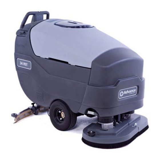
34 RST, 34 RST EcoFlex Service Manual Advance Models: 56315900(34RST D), 56315901(34RST D-C) 56315902(34RST D-C / W/Strainer) 56315903(34RST D-C / W/Battery Watering) 56381029 (34 RST X34D) 56381031 (34 RST X34D-C), 56381809 (34RST D-C Strainer HD) 4/08 revised 12/13 FORM NO. 56043115... -
Page 2: Table Of Contents
Table of Contents Table of Contents Introduction . . . . . . . . . . . . . . . . . . . . . . . . . . . . . . . . . . . . . . . . . . . . . . . . . . .5 Parts and Service Nameplate Other Manuals Available For Your Machine... - Page 3 Table of Contents Solution System . . . . . . . . . . . . . . . . . . . . . . . . . . . . . . . . . . . . . . . . . . . . . . . . 37 Functional Overview Circuit Overview Electrical Diagram...
- Page 4 Table of Contents Palm Drive Button Replacement Testing the Reverse Button Reverse Button Replacement Testing the Speed Limit Control Potentiometer Speed Limit Control Potentiometer Replacement Electrical System . . . . . . . . . . . . . . . . . . . . . . . . . . . . . . . . . . . . . . . . . . . . . . . 72 Schematic Batteries Description of the Low Voltage Cut-Out Feature...
-
Page 5: Introduction
Repairs should be performed by your Authorized Nilfisk-Advance Service Center, who employs factory trained service personnel, and maintains an inventory of Nilfisk-Advance original replacement parts and accessories. Call the NILFISK-ADVANCE DEALER named below for repair parts or service. Please specify the Model and Serial Number when discussing your machine. -
Page 6: Conventions
Introduction Conventions Forward, backward, front, rear, left or right are intended with reference to the operator’s position, that is to say in operating position with the hands on the handlebar. Transporting the Machine Caution! Before transporting the machine on an open truck or trailer, make sure that •... -
Page 7: General Safety Instructions
Introduction General Safety Instructions Warning! ◦ This machine should be used only by properly trained and authorized persons. ◦ Never work under a machine without safety blocks or stands to support the machine. ◦ Keep sparks, flame and smoking materials away from batteries. Explosive gases are vented during normal operation. -
Page 8: Technical Specifications
Introduction Technical Specifications Voltage 36-Volt Power Source (6) 6-volt Batteries (wet acid and gel cell available) Battery Capacity 305 amp-hrs. Protection Grade IPX3 Onboard Battery Charger 36-volt, 25-amp Wet/Gel Compatible Solution Control Pulse-control gravity feed Solution Tank 30 gal. (114 L) Recovery Tank 30 gal. - Page 9 Introduction Technical Specifications (continued) 9 - FORM NO. 56043115 - 34 RST...
-
Page 10: Maintenance Schedule
Introduction Maintenance Schedule Maintenance intervals given are for average operating conditions. Machines used in severe operational environments may require service more often. MAINTENANCE ITEM Daily Weekly Monthly Yearly Charge the Batteries Check/Clean Tanks and Hoses (clean recovery tank switch and vacuum inlet screen) Check/Clean/Rotate the Brushes/Pads Check/Clean the Squeegee Check the Water Level in each Battery Cell (does not apply to gel cell batteries) -
Page 11: Pm Checklist
Advance 34 RST Models PM Checklist Defect Codes Customer needs adjustment binding Address dirty or contaminated damaged, bent or torn City leaks missing W worn out Model Serial No. Hours Does OPERATIONAL INSPECTION ITEMS Defect Codes (circle) Work Palm Drive Button and Reverse Button Operation (check for Fwd/Rev Drive) Drive System Performance (Speed Changes Min/Max) noisy sluggish Scrub System (Raise/Lower, Brush Motor On/Off) -
Page 12: Know Your Machine
Introduction Know Your Machine As you read this manual you will occasionally run across a bold number or letter in parentheses - example: (2). These numbers refer to items shown on the following pages unless otherwise noted. Refer to these pages for the location of items highlighted in bold in the text. - Page 13 Introduction 16 Solution Drain Hose/Level Indicator 25 Squeegee Mount Thumb Nut 17 Squeegee Raise/Lower Lever 26 Squeegee Adjustment Knob 18 Battery Pack Connector (non onboard charger models only) 27 Recovery Tank Drain Hose 19 Recovery Hose 28 Reverse Button 20 Wheel Drive Circuit Breaker 29 Palm Drive Buttons 21 Circuit Breaker for the Control Circuit 30 Speed Limit Control Knob...
- Page 14 Introduction Control Panel Assy Motor, Right Brush Speed Control Motor, Vac Battery (Not Shown) Motor, Brush Actuator Fuse, 150 Amp Potentiometer, 100K Ohm, Speed Limit Circuit Breaker, 5 Amp Switch, Key Circuit Breaker, 30 Amp Switch, Float (Recovery Tank Full) Contactor, Brush Motor Switch, Reverse Contactor, Vac Motor...
-
Page 15: Control Panel
Control Panel Control Panel Standard Models Key Switch (Main Power) Scrub ON Switch Solution Switch I1 – Regular Scrub ON Indicator B1 Solution Indicator I2 – Heavy Scrub ON Indicator D1 Solution Flow Indicator I1 and I2 – Extreme Scrub ON Indicators Vacuum Switch Display C1 Vacuum System Indicator... -
Page 16: Ecoflex Models
Control Panel EcoFlex Models Key Switch (Main Power) Solution Switch Vacuum Switch Display Panel Solution Flow Indicator Fault Indicator Hour Meter Detergent Indicator Battery Indicator Scrub Pressure Indicator Recovery Tank FULL Indicator Battery Low Indicator Wand Switch (Dealer Installed Option) Detergent System (EcoFlex models only) EcoFlex Switch Scrub OFF... -
Page 17: Functional Description
Control Panel Functional Description The control panel is an integral component with the Main controller (A1) circuit board. The controls on the 34 RST were designed with one touch operation in mind. For single-pass scrubbing the user can simply depress one switch and all systems on the machine will be ready to go. -
Page 18: Description Of Indicators
Control Panel Chemical Switch (F): The chemical (detergent mixing) option is available on EcoFlex models. Pressing this switch will turn on or off the chemical option. When active, a small pump will inject chemical (detergent) into the solution line upstream from the scrub deck. The chemical pump is disabled any time the solution system is inactive. See the main programming options in this manual to select (activate) the onboard chemical distribution system. -
Page 19: Scrub Mode Indicators
Control Panel Vacuum System (C) Indicator: • This indicator will be off if the vacuum is disabled and turned off. • This indicator will be green if the vacuum is on. • This indicator will flash green if the vacuum is in the 10 second delayed-off condition. •... -
Page 20: Battery Indicator
Control Panel Battery Indicator The charge state of the battery is shown in the main display area of the control panel. For standard models, this is indicated by three colored LED’s (J1). For EcoFlex models, this is shown with a bar graph (D5) in the main display. For EcoFlex models, when the battery is depleted and needs to be charged, the charge indicator (D8) will be displayed. -
Page 21: Main Controller
Control Panel Main Controller The Main controller (A1), which includes the control board and the display, is the primary electronic control for the machine and its functions (except drive control). The control board is the basic input/output device and contains a micro- contoller chip to regulate function. -
Page 22: Displaying The Control Board Revision Level
Control Panel Displaying the Control Board Revision Level During machine service, it may be helpful to know the control board revision level to determine machine configuration. To view the control board revision level: EcoFlex Models: Turn the key switch to the off position. While holding the Scrub Off (H) and Chemical (F) switches depressed, turn on the key switch. -
Page 23: Turning Fault Detection On Or Off
Control Panel Turning Fault Detection On or Off: If a fault occurs in a particular system, that system (and possibly others) will be shut down. This can make troubleshooting the system difficult. This option will allow service personnel to disable some of the fault detection checks to facilitate troubleshooting. -
Page 24: Selecting Machine Type (Ecoflex Version Only)
Control Panel Selecting Machine Type (EcoFlex version only) Selecting the machine type must be done before selecting the scrub deck type in order for the correct scrub deck values to be available. This menu is only available on EcoFlex version machines and not the AXP or ST versions. Turn the key switch to the off position. -
Page 25: Scrub Deck Down Time Period Adjustment
Control Panel Scrub Deck Down Time Period Adjustment The initial lowering of the scrub deck is timed, because there will not be any brush motor amperage to monitor for determining when to stop lowering the deck. The time that the deck is lowered is adjustable from 3.5 seconds to 4.4 seconds in 0.1-second increments. -
Page 26: Scrub Deck Pressure, Solution Flow Rate, And Chemical Flow Rate Adjustments
Control Panel Scrub Deck Pressure, Solution Flow Rate, and Chemical Flow Rate Adjustments Each of the scrub settings (Regular, Heavy, and Extreme) affects the scrub deck pressure, solution flow rate, and chemical flow rate (if equipped). These settings are adjustable. The default values are shown in the tables below. The scrub pressures are determined by examining the amperage through the brush motors. -
Page 27: Regular Scrub Setting Adjustment
Control Panel Regular Scrub Setting Adjustment Use this procedure to adjust the scrub deck pressure, solution rate, and chemical rate that are used for the Regular scrub mode. Turn the key switch to the off position. For EcoFlex models, while holding the Scrub On (I) and Wand (E) switches depressed, turn the key switch to the on position. -
Page 28: Heavy Scrub Setting Adjustment
Control Panel Heavy Scrub Setting Adjustment: Use this procedure to adjust the scrub deck pressure, solution rate, and chemical rate that are used for the Heavy scrub mode. Turn the key switch to the off position. For EcoFlex models: a. While holding the Scrub On (I) and Chemical (F) switches depressed, turn the key switch to the on position. -
Page 29: Extreme Scrub Setting Adjustment
Control Panel Extreme Scrub Setting Adjustment Use this procedure to adjust the scrub deck pressure, solution rate, and chemical rate that are used for the Extreme scrub mode. Turn the key switch to the off position. For standard models: a. While holding the Scrub On (I) and Solution (B) switches depressed, turn the key switch to the on position. -
Page 30: Troubleshooting Guide
Control Panel Troubleshooting Guide Any error codes detected by the main control board will be displayed on the display panel as they occur. If more than one error exists the display will sequence through the error codes at one-second intervals. On EcoFlex models the error (D2) will display as a mechanical wrench symbol followed by a two-digit code. - Page 31 Control Panel Error Description Comments Solenoid Bank Coil Circuit The sum of the currents through these coils is too high Overload • Inspect the “B-3” ground bus (J2-9 wire) at the controller • Brush Motor Contactor (K1) for negative battery voltage. This error will occur if B-3 is •...
-
Page 32: Main Controller I/O Table
Control Panel Main Controller I/O Table B- = Battery Negative B+ = Battery Positive Signal Nominal Reference Designation Pin Wire Color Description Range Comments Type Value Pulsed Signal equal to the Fault Input J1-4 ORN/BLU Speed Control Status -36V 37.6 - 30.6V Code flashed by the Speed Control Built-in Status LED Machine is not in Neutral (a palm... -
Page 33: Service Test Mode
Control Panel Service Test Mode To assist in the troubleshooting and servicing of the electrical system and related components, a special test mode allows independent control of the various outputs and monitoring of the various inputs. To enter the service test mode perform the following step: Turn the key switch to the off position. -
Page 34: Test Mode Output Controls
Control Panel Test Mode Output Controls The control panel switches are used to control various output functions of the Main controller while in Test Mode. Below is a list of each switch and the function it controls. Following the list is a detailed description of each function. Scrub off Switch (H): Controls the brush motors. - Page 35 Control Panel Scrub On Switch (I) This switch is used to control the output to the scrub deck lift actuator. Pressing and releasing this switch will cycle the actuator output through 4 states. These are: 1 – Output off, direction = up 2 –...
- Page 36 Control Panel • Check the Blu wire of the main harness connector at the vacuum motor to battery Negative. If no voltage repair or replace wire. • Check the Blk wire of the main harness connector at the vacuum motor to battery Positive. If no voltage repair or replace wire.
-
Page 37: Solution System
Solution System Solution System Functional Overview The main body of the machine also serves as the solution tank. The solution tank has a fill capacity of 30 gallons (114 liters). All models use one right rear tank fill opening for ease of filling. A serviceable Solution Filter is plumbed into the manual solution shutoff valve outlet to keep debris from entering the solenoid valve. -
Page 38: Circuit Overview
Solution System Circuit Overview The 34 RST machines do not use a solution pump. The gravity-fed solution rate is controlled by cycling the solution solenoid on and off at the rates shown in the table below. The three solution flow rates listed are managed by the A1 control board’s negative voltage output from the terminal J1-11 Red/Grn wire. -
Page 39: Maintenance
Solution System Maintenance • Solution Tank: Empty the solution tank weekly; remove the solution Drain Hose from its storage area (located on the right rear control handle compartment). Direct the hose to a designated “Disposal Site” and flush the tank with clean water. -
Page 40: Removal And Installation
Solution System Removal and Installation Solenoid Valve Removal Drain the solution tank or turn off the solution ball valve to prevent solution loss. Shut off the key switch and disconnect the battery connector. Note: You may want to jack up the left side of the machine for better access to the Solenoid Valve (H) and associated hardware. If you choose to jack up the machine, make sure you support the machine with safety stands or blocking to prevent the machine from dropping and possibly causing personal injury or machine damage. Never work under machine without safety stands or blocking to support the machine. Warning! Unplug the L1 solenoid valve Connector Assembly (G) from the machine harness. -
Page 41: Solution Filter And Ball Valve Removal
Solution System Solution Filter and Ball Valve Removal Drain the solution tank using the solution drain hose (B). Loosen the 2 Hose Clamps (R) and carefully remove (pry off) the solution Inlet Hose (S) and Outlet Hose (T) from the Filter/Valve Assembly (F). Remove the 2 Hose Clamps (U) that secure the Filter/Valve Assembly (F) to the chassis and remove the Filter/ Valve Assembly (F) from the machine. -
Page 42: Scrub System
Scrub System Scrub System Functional Overview The 34 RST models use the disc-type scrub system powered by (2) 3/4 HP motor gearbox assemblies. Note: Recovery Tank Full switch must be open (Tank empty). On all models the scrub deck platform is raised and lowered automatically by a vertically-mounted electric lift actuator motor. -
Page 43: Electrical Diagram
Scrub System Electrical Diagram FIGURE 1 FUSE, 150 A. FUSE, 150 A. BATTERY BATTERY 36 VDC CONTROL BOARD J2-7 CIRCUIT BREAKER, 5 AMP CIRCUIT BREAKER, 5 AMP VIO/YEL J2-1 BRUSHACTUATOR2 VIO/BLK WHT/GRN J1-14 J2-8 BRUSHCONTACTOR BRUSHACTUATOR1 MOTOR, BRUSHACTUATOR MOTOR, BRUSHACTUATOR COIL, BRUSHMOTORCONTACTOR COIL, BRUSHMOTORCONTACTOR J2-4... -
Page 44: Removal And Installation
Scrub System Removal and Installation Motor Gimbal Make sure the scrub brush deck is in its raised position, then turn the key switch off and disconnect the battery pack. Disconnect the battery pack connector before servicing machine. Caution! See Figure 2. Unlatch and remove the left- and right-hand Brush Housings (A and B). Push the brushes/pads straight down to remove them from the Motor Gimbals (C). -
Page 45: Scrub Brush Deck
Scrub System Scrub Brush Deck With scrub brushes installed, lower the scrub brush deck, turn the key switch off and disconnect the battery pack. Disconnect the battery pack connector before servicing machine. Caution! Note: If the battery pack is connected and the key switch is switched on when the scrub brush deck is lowered, the deck will automatically rise to its upper limit. This could cause personal injury or machine damage. Remove the front nose cone by firmly grasping the lower part and lifting straight up. See Figure 2. -
Page 46: Scrub Brush Lift Actuator
Scrub System Scrub Brush lift Actuator See Figure 3. With scrub brushes installed, lower the scrub brush deck, turn the key switch off and disconnect the battery pack. Note: If the lift actuator motor will not run, go to step 2, then shim up the brush deck to relieve the pressure on the connecting hardware to ease removal of the Lift Actuator Assembly (T). Remove the front nose cone by firmly grasping the lower part and lifting straight up. Disconnect the actuator motor wiring harness pigtail connector. -
Page 47: Scrub Brush Motor/Gearbox
Scrub System Scrub Brush Motor/Gearbox Remove the scrub deck from the machine following the steps in the Scrub Brush Deck Removal section. Turn the brush deck on its back. See Figure 2. Remove the brushes/pads from the Motor Gimbals (C). If removing both Motor / Gear Unit Assemblies (J), mark the location of the Assemblies on the Deck Weldment (N) for correct reassembly. -
Page 48: Recovery System
Recovery System Recovery System Functional Overview See Figure 1. Dirt and water are lifted off the floor into the recovery tank by airflow created by a three-stage 36V vacuum motor. The wastewater and air enter the vacuum system at the squeegee tool through small openings (notches) in the front squeegee blade. -
Page 49: Vacuum Motor Control Circuit Overview (Auto Mode)
Recovery System Vacuum Motor Control Circuit Overview (Auto Mode) + (Positive) Circuit input starts with: • A closed S3 key switch supplies the needed positive voltage to the A1 control board J1-13 (Brn wire). Note: The A1 control board scrub-on button must also be depressed (enabled). This operator command lowers the brush deck. -
Page 50: Maintenance
Recovery System Maintenance Service Maintenance Checklist Whenever there is a vacuum problem, it’s best to check over the entire system. Use the checklist below as a guide to thoroughly check the vacuum system. □ Inspect and clean the vacuum motor float switch. (If the switch is closed [tipped up] the vacuum motor will not operate) □... -
Page 51: Maintenance Of The Recovery Tank Float Switch
Recovery System Maintenance of the Recovery Tank Float Switch If the recovery tank float switch becomes dirty it can impair the operation of the recovery system. A dirty vacuum shutoff switch can cause the vacuum motor to not function at all, or fail to shut off when the tank is full. If daily rinsing of the recovery tank is not sufficient to keep the switch clean you may need to remove the float arm for cleaning. -
Page 52: Maintenance Of Vacuum Motor Inlet Screen
Recovery System Maintenance of Vacuum Motor Inlet Screen See Figure 4. The Vacuum Motor Inlet Screen (4) should be cleaned on a daily basis. DO NOT run water down the screen in an attempt to clean it. If you do this you will be running water directly into the vacuum motor. To remove the Vacuum Motor Inlet Screen (4) from the recovery tank, grip, twist and pull up on the Vacuum Motor Inlet Screen (4). -
Page 53: Removal And Installation
Recovery System Removal and Installation Vacuum Motor Removal Drain the Recovery Tank (A) using the drain hose. Turn the key switch off and disconnect the battery pack. Swing open the recovery tank and disconnect the vacuum motor harness connector. See Figure 5. Carefully pull the Acoustical Foam vacuum exhaust hose (B) out of the P-Clamp (C) on the Recovery Tank (A). -
Page 54: Recovery Tank Removal
Recovery System Recovery Tank Removal If you wish to remove the vacuum motor from the Recovery Tank (A), do so by following steps 1-6 in the Vacuum Motor Removal section. Disconnect the electrical connector to the Float Switch (K). Note that you may need to cut a cable tie to access the connector. -
Page 55: Squeegee System
Squeegee System Squeegee System Maintenance Squeegee Lift Linkage Adjustment See the Know Your Machine section in this manual. The squeegee pick-up tool is raised and lowered manually by a rear control panel mounted Lever (17). Squeegee Lift Lever Adjustment The squeegee tool’s storage and operating positions are adjustable. To adjust the squeegee position: Lower the squeegee assembly to the floor. -
Page 56: Servicing The Squeegee
Squeegee System Servicing the Squeegee If the squeegee leaves narrow streaks or water, the blades may be dirty or damaged. Remove the squeegee, rinse it under warm water and inspect the blades. Reverse or replace the blades if they are cut, torn, wavy or worn. To Reverse or Replace the Rear Squeegee Wiping Blade: See Figure 2. -
Page 57: Removal And Installation
Squeegee System Removal and Installation Squeegee Mount Assembly Removal Turn the key switch off and disconnect the battery pack. See Figure 3. Disconnect the Squeegee Hose (19) and remove the Squeegee Assembly (13) from the machine. Lower the Squeegee Lever (17) and disconnect the Squeegee Lift Cable (C) from the Squeegee Mount Assembly. Service Note: The downward spring force on the squeegee mount weldment can make it difficult to remove and reinstall the Squeegee Mount Assembly. You may choose to remove the squeegee level Wheels (F) from the Squeegee Mount Assembly, or jack up the machine to reduce the effect of the downward spring force. -
Page 58: Caster Wheel Removal
Squeegee System Caster Wheel Removal Turn the key switch off and disconnect the battery pack. Never work under machine without safety stands or blocking to support the machine. Warning! Drain both the solution and recovery tanks. Remove the squeegee assembly and have the scrub brush deck in the up (stored) position with the scrub brushes installed. -
Page 59: Wheel Drive System
Wheel Drive System Wheel Drive System Functional Overview See Figures 1 and 2. A 375 watt (0.5 HP) permanent magnet (36V) motor transaxle (M1) is used for the wheel drive on all machines. A Curtis PMC solid state speed controller (A2) regulates the variable speed and Fwd/Rev wheel drive motor functions. -
Page 60: Electrical Diagram
Wheel Drive System Electrical Diagram Note: For a complete description of all callouts see the Electrical System/Wiring Diagram/Schematic section in this manual. FIGURE 2 FUSE, 150 A. FUSE, 150 A. BATTERY BATTERY 36 VDC CONTROL BOARD J2-7 CIRCUIT BREAKER, 5 AMP CIRCUIT BREAKER, 5 AMP J2-1 BRUSHACTUATOR2 J1-14... -
Page 61: A2 Speed Controller Pin Key Detail
Wheel Drive System FIGURE 3 WHEEL DRIVE SYSTEM A1 Speed Control Pin Connection 4.7K POT WIPER POT HIGH R1 Speed Limit 100K Ohms POT LOW This drawing shows additional controller input circuit detail. The R1 speed limit pot is shown at its maximum speed setting, with the wiper pin #18 shorted to the pot high pin #3. -
Page 62: Wheel Drive Troubleshooting Guide
Wheel Drive System Wheel Drive Troubleshooting guide Problem Possible Cause No wheel drive in Forward or Reverse Wheel drive motor circuit breaker (F3) tripped (reset 30A circuit breaker). • Control circuit breaker (F2) tripped (reset 5A circuit breaker). • Defective S6 & S7 palm drive switches and or circuit wiring (repair or •... -
Page 63: Removal And Installation
Wheel Drive System Removal and Installation Drive Motor Transaxle Removal Turn the key switch off and disconnect the battery pack. Disconnect the battery pack before servicing machine. Warning! Never work under machine without safety stands or blocking to support the machine. Warning! Drain both the solution and recovery tanks and remove the squeegee. -
Page 64: Drive Motor Transaxle Removal (Continued)
Wheel Drive System Drive Motor Transaxle Removal (continued) Service Note: You may find it easier to loosen the wheel Nuts (A) slightly when the wheels are still on the ground and before you jack up the machine. See Figure 5. Jack the front of the machine from this location until the drive wheels are approximately 1” off the ground. Remove the (6) wheel Nuts (A) and remove the (2) Drive Wheels (B) from the Motor Transaxle (D). Disconnect the drive motor wiring connector. -
Page 65: Drive Wheel Removal
Wheel Drive System Drive Wheel Removal Turn the key switch off and disconnect the battery pack. Disconnect the battery pack before servicing machine. Warning! Never work under machine without safety stands or blocking to support the machine. Warning! Remove the squeegee. Place wood blocking in the front and rear of the Drive Wheel (F) opposite of the one that you are removing to prevent the machine from rolling. -
Page 66: Testing The Palm Drive Buttons
Wheel Drive System Testing the Palm Drive Buttons See Figure 7. Disconnect the Handle Harness (H) from the mating connector located to the left of the squeegee raise/lower handle. See Figure 8. Use a continuity checker or ohmmeter to check the continuity between pins 4 and 6 on the Handle Harness (H). -
Page 67: Palm Drive Button Replacement
Wheel Drive System Palm Drive Button Replacement Note: It’s recommended that you empty the Recovery Tank before replacing a Palm Drive Button. See Figure 7. Remove the (2) Phillips Flat Head Screws (I) and remove the Palm Switch Assembly (J) from the Handle (K). See the detail in Figure 7. Remove the (2) Phillips Pan Head Screws (L) and Flat Washers (M) and remove the Palm Button Switch (N) and (2) Switch Springs (O) from the Palm Switch Housing (P). -
Page 68: Testing The Reverse Button
Wheel Drive System Testing the Reverse Button See Figure 9. Disconnect the Handle Harness (H) from the mating connector located to the left of the squeegee raise/lower handle. See Figure 8. Use a continuity checker or ohmmeter to check the continuity between pins 3 and 5 on the Handle Harness (H). -
Page 69: Reverse Button Replacement
Wheel Drive System Reverse Button Replacement Turn the key switch off and disconnect the battery pack. Note: It’s recommended that you empty the Recovery Tank before replacing the Reverse Button. Pull the Drain Hose out of the brackets to access the 5/16”-18 Hex Head Screws (U & Z). Disconnect the Handle Harness (H) from the mating connector located to the left of the squeegee raise/lower handle. -
Page 70: Testing The Speed Limit Control Potentiometer
Wheel Drive System Testing the Speed Limit Control Potentiometer See Figure 9. Disconnect the Handle Harness (H) from the mating connector located to the left of the squeegee raise/lower handle. See Figure 8. Use an ohmmeter on pins 1 and 4 to check the total resistance of the potentiometer. If the potentiometer is working correctly, the resistance across pins 1 and 4 should measure approximately 100K ohms. - Page 71 Wheel Drive System 15. Check the position of the gray indicator on the Knob (AA) with the Potentiometer (AB) set to both the full clockwise (fast) and full counterclockwise (slow) positions. Readjust the rotational position of the Knob (AA) on the Potentiometer (AB) shaft as necessary to center the indicator to the Handle (K).
-
Page 72: Electrical System
Electrical System Electrical System Schematic (OPTIONAL) ONBOARDBATTERY CHARGER NOTE: CONNECT GRNWIRE TOF2 ANDDISCONNECT REDWIRE FROMF2 FORCHARGEROPTION INTERLOCK BLK/WHT CIRCUIT BREAKER, 5 AMP CIRCUIT BREAKER, 5 AMP FUSE, 150 A. FUSE, 150 A. BATTERY BATTERY 36 VDC CONTROL BOARD J2-7 CIRCUIT BREAKER, 5 AMP CIRCUIT BREAKER, 5 AMP VIO/YEL J2-1... -
Page 73: Batteries
• Use a combination of multiple two-volt cell units to construct a 36-volt DC battery pack system. • Nilfisk-Advance recommended battery pack capacity is a 305 AH @ 20 Hour Rate deep cycle battery system. Note: The battery pack must fit the battery compartment size listed in Specifications. -
Page 74: Battery Maintenance
Electrical System Battery Maintenance Charging Batteries Charge the batteries each time the machine is used or when the battery indicator (1 or 3) is reading less than full. Note: Refer to the algorithm chart in Advance Technical Service Bulletin TSBUS2008-984 for the correct charging algorithm for your battery type and model. Caution! • Charge batteries in a well-ventilated area. • Do not smoke while servicing the batteries. •... -
Page 75: Removal And Installation
Electrical System Removal and Installation Caution! • Use extreme caution when working with batteries. Sulfuric acid in batteries can cause severe injury if allowed to contact the skin or eyes. • Explosive hydrogen gas is vented from the batteries through openings in the battery caps. Do not smoke while servicing the batteries. -
Page 76: Maintenance And Adjustment
Electrical System Maintenance and Adjustment Lift Actuator Limit Adjustment To protect the lift actuator from traveling too far, it contains two internal limit switches for minimum and maximum travel. The minimum travel is adjusted by turning the leadscrew nut, and the maximum travel (or length) is adjusted by turning the dial at the top of the leadscrew motor. - Page 77 Electrical System 10. Remove the dust cap (6) from the top of the gear housing (5) using your fingers or a small screw driver. 11. Place a 1/2” socket (9) over the limit adjustment nut (7) to turn the nut, and increase or decrease the lower limit as follows: •...
-
Page 78: Curtis Controller Diagnostics
Diagnostics Using the Curtis Handheld Programmer Note: Also refer to the Curtis Programmer Manual, Nilfisk-Advance form number 56043101, for more details on programmer operation. With a Curtis programmer, diagnostics and troubleshooting is more direct than with the LEDs alone. The programmer presents complete diagnostic information in plain language with no codes to decipher. -
Page 79: Drive Status Led Fault Codes
Electrical System Drive Status LED Fault Codes TABLE 1 Status Light Explanation Possible Cause Code Display over-/under-temperature cutback 1. Temperature >92°C or < -25°C. 2. Excessive load on vehicle. 3. Operation in extreme environments. 0 00 throttle fault 1. Palm drive switch wires open or shorted. 2. -
Page 80: Speed Control Programming Options
Electrical System Speed Control Programming Options Following are the two speed control parameters that can be adjusted using a Curtis handheld programmer: M1 MAX SPD – Forward Transport/Scrub maximum speed limit (% of full throttle) M1 REV MAX SPD – Reverse Transport/Scrub maximum speed limit (% of full throttle) Installation Checkout for the Curtis Speed Controller After installing a controller and before operating the vehicle, carefully complete the following checkout procedure.
Need help?
Do you have a question about the 34 RST EcoFlex and is the answer not in the manual?
Questions and answers