
Related Manuals for Rear view safety RVS-718 DCT


Summary of Contents for Rear view safety RVS-718 DCT
-
Page 1: Instruction Manual
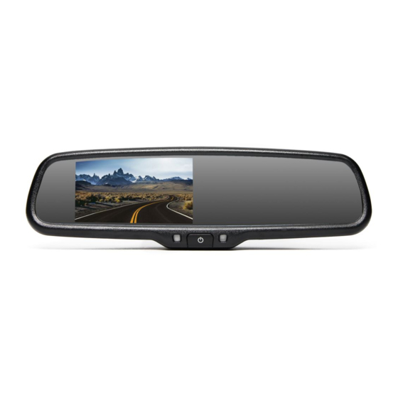
Instruction Manual G-Series Rear View Replacement Mirror Monitor RVS-718 DCT Rear View Safety, Inc. © 2016 Reverse With Confidence ™... - Page 2 Troubleshooting......15 Warranty & Disclaimer......16-17 Rear View Safety...
- Page 3 NOTE! Please read all of the installation instructions carefully before installing the product. Improper installation will void manufacturer’s warranty. Congratulations on purchasing a Rear View Backup Camera System! With this manual you will be able to properly install and operate the unit. The Backup Camera System is intended to be installed as a supplement aid to your standard rear view mirror that already exists in your vehicle.
- Page 4 Rear View Camera System. If you back up while looking only at the monitor, you may cause Rear View Safety...
-
Page 5: Installation
INSTALLATION: • Electric shock or product or disconnected wire may cause a malfunction may occur if this fire. product is installed incorrectly. • While installing the Rear View System be careful with the wire • Use this product within positioning in order to avoid wire the voltage range specified. - Page 6 If you have questions about this product, contact: Rear View Safety 1797 Atlantic Avenue Brooklyn, NY 11233 Tel: 1.800.764.1028 IN NO EVENT SHALL SELLER OR MANUFACTURER BE LIABLE FOR ANY DIRECT OR CONSEQUENTIAL DAMAGES OF ANY NATURE, OR LOSSES OR EXPENSES RESULTING FROM ANY DEFECTIVE PRODUCT OR THE USE OF ANY PRODUCT.
- Page 7 Before drilling please check that no cable or wiring is on the other side of the wall. Please clamp all wires securely to reduce the possibility of them being damaged while vehicle is in use. Keep all cables away from hot or moving parts and electrical noisy components. We recommend doing a benchmark test before installation to insure that all components are working properly.
- Page 8 Do not run the cable over sharp edges, do not kink the cable and keep away from HOT and rotating parts. Fasten all cables and secure all excess cable. Connect camera to the camera extension cable which runs inside the vehicle. Figure 1.2 Rear View Safety...
- Page 9 Wiring After connecting the camera to the “camera cable” the camera should be plugged into AV2 input. Connect the RED 12V power wire to a an ignition power source and the BLACK 12V ground wire to a chassis ground. The GREEN wire is the REVERSE trigger wire. Connect this wire to the vehicle’s backup light circuit to activate the rear-view image whenever the vehicle shifts into reverse.
- Page 10 0.2M space from the car. Accuracy The accuracy of the grid-lines can vary based on how you angle your cam- era. Therefore to conpensate for inaccurancies, you can adjust the grid-lines to your camera angle. Rear View Safety...
- Page 11 FIGURE 1.1 FIGURE 1.2 Reverse With Confidence ™...
- Page 12 FIGURE 2.1 1. RED- Power (+) 2. YELLOW- Video 3. GREEN- Mirror / Normal Imaging 4. WHITE- Audio 5. BLACK- Ground (-) Rear View Safety...
- Page 13 FIGURE 2.2 Reverse With Confidence ™...
-
Page 14: Digital Compass Calibration
3. Drive your vehicle in at least 2 circles counterclockwise, allowing 90 seconds to complete one circle. 4. Keep your circle radius close to 5 meters and your speed less than 10km/h for the most accurate calibration. 1-3. Rear View Safety... - Page 15 5. Press “SEL/REC” to select the “CALIBRATION”, press “UP” “DOWN” , select the “OFF” 1-4 Caution 1. Make sure the rear view mirror is clearly visable to the driver before calibration. 2. Do not calibrate the compass near a large truck. 3.
- Page 16 Temperature Setting (Option) How switch the temperature unit. Press the “MENU” enter into “SETTING” menu, and press “SEL/REC” button to choose the “TEMP UNIT”. press “UP” “DOWN” you can switch °F to °C 4-1. Rear View Safety...
-
Page 17: Temperature Sensor Installation
Temperature Sensor Installation Locate the temperature sensor between the front of the radiator and the front bumper. Slide the metal clip over the edge of the sheet metal or plasic shield until it is secure. Do not install the temperature sensor near the engine. The Distribution Of Magnetic Fluxline We do not recommend using the compass in an area with high magnetic lines of flux. - Page 18 Rear View Safety...
- Page 19 Reverse With Confidence ™...
-
Page 20: Specifications
Screen Size: 4.3” Display Screen: TFT-LCD Display Resolution: 400(H)x234(V) Aspect Ratio: 16:9 Color Depth: 16.7M dithering Pixel Pitch (mm) 0.219x0.219 Power Consumption: Working Voltage: DC12V VIDEO-IN to GPS/DVD Video Input: (Default) Camera to backup camera Signal System: PAL/Auto/NTSC Rear View Safety... - Page 21 No Image On Screen • Do a hard reset, unplug all cables • Verify camera is on correct camera and power cables, leave out for 1 input minute and then re-connect them • Verify cable is connected to • Check to ensure that the monitor connection to the camera is tight •...
-
Page 22: One Year Warranty
OTHERS OR THE UNAUTHORIZED USE OF NONCONFORMING PARTS; THE DAMAGE IS DUE TO NORMAL WEAR AND TEAR, THIS DAMAGE IS DUE TO ABUSE, IMPROPER MAINTENANCE, NEGLECT OR ACCIDENT; OR THE DAMAGE IS DUE TO USE OF THE REAR VIEW SAFETY, INC. SYSTEM AFTER PARTIAL FAILURE OR USE WITH IMPROPER ACCESSORIES. - Page 23 FOR ANY INJURY, LOSS OR DAMAGE, INCIDENTAL OR CONSEQUENTIAL, ARISING OUT OF THE USE OR INTENDED USE OF THE PRODUCT. IN NO EVENT SHALL REAR VIEW SAFETY AND/OR ITS AFFILIATES HAVE ANY LIABILITY FOR ANY LOSSES (WHETHER DIRECT OR INDIRECT, IN...
- Page 24 If you have any questions about this product, contact: Rear View Safety, Inc. 1797 Atlantic Avenue Brooklyn, NY 11233 800.764.1028 Better Cameras. Better Service. IT’S OUR GUARANTEE. Rear View Safety...
Need help?
Do you have a question about the RVS-718 DCT and is the answer not in the manual?
Questions and answers