Table of Contents
Advertisement
Quick Links
Advertisement
Table of Contents

Subscribe to Our Youtube Channel
Related Manuals for Rear view safety RVS-718F150


Summary of Contents for Rear view safety RVS-718F150
- Page 2 What’s in the Box?
-
Page 3: Table Of Contents
Table of Contents Introduction ....................4 Safety Information ..................5-7 Before Beginning Installation..............8 Installation Guide..................9 Installation Guide + Tips................10 Adjustable Grid Line ..................11 Installation and Wire ................12 How To Wire....................13 Splicing ......................14 Positioning....................Monitor Dimensions..................16 Monitor Specifications................17 Camera Dimensions...................18 Camera Specifications................19 Troubleshooting..................20 Warranty.......................21 Disclaimer ....................22... -
Page 4: Introduction
TV viewer or screen located for- ward of the back of the driver’s seat or in any location that is vis- ible, directly or indirectly, to the driver while operating the vehicle. REAR VIEW SAFETY... -
Page 5: Safety Information
Safety Information Please read the entire manual and follow the instructions and warnings carefully. Failure to do so can cause serious damage and/or injury, including loss of life. Be sure to obey all applica- ble local traffic and motor vehicle regulations as it pertains to this product. -
Page 6: Installation
Dropping the unit may cause is detected, disconnect the possible mechanical failure. system immediately. • Where the power cable may touch a metal case, cover the cable with a friction tape. A short circuit or disconnected wire may cause a fire. REAR VIEW SAFETY... -
Page 7: Safety Information
Safety Information If you have questions about this product, contact: Customer Service: Rear View Safety 1797 Atlantic Avenue Brooklyn, NY 11233 Tel: 1.800.764.1028 IN NO EVENT SHALL SELLER OR MANUFACTURER BE LIABLE FOR ANY DIRECT OR CONSEQUENTIAL DAMAGES OF ANY NATURE, OR LOSSES OR EXPENSES RESULTING FROM ANY DEFECTIVE PRODUCT OR THE USE OF ANY PRODUCT. - Page 8 Install split grommets where applicable. Step 3: Once all cables and wiring have been properly routed, perform a system function test by temporarily connecting the system. If the system seems to not be operating properly see troubleshooting (page 20). REAR VIEW SAFETY...
-
Page 9: Installation Guide
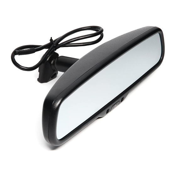
Installation Guide Mirror The mirror monitor replaces the existing car mirror. Carefully remove the mirror off the “pin”. Slide the replacement mirror onto the pin and se- cure it with the screw provided (already in the screw hole). There are many methods to remove the original rear-view mirror, however, please don’t force the mirror off the bracket. -
Page 10: Installation Guide + Tips
Installation Guide + Tips REAR VIEW SAFETY... -
Page 11: Adjustable Grid Line
Adjustable Grid Line Reverse With Confidence ™... -
Page 12: Installation And Wire
Installation and Wire Figure 1.1 Figure 1.2 REAR VIEW SAFETY... -
Page 13: How To Wire
How To Wire Figure 2.1 Reverse With Confidence ™... -
Page 14: Splicing
Splicing 1. Red - Power (+) 2. Yellow - Video 3. Green - Mirror / Normal Imaging 4. White - Audio 5. Black - Ground (-) REAR VIEW SAFETY... -
Page 15: Positioning
Positioning Reverse With Confidence ™... -
Page 16: Monitor Dimensions
Monitor Dimensions REAR VIEW SAFETY... -
Page 17: Monitor Specifications
Monitor Specifications TFT LCD Digital Monitor Screen Size 4.3” Display Screen TFT-LCD Display Resolution 400(H)x234(V) Aspect Ratio 16 : 9 Color Depth 16.7M dithering Pixel Pitch (mm) 0.219X0.219 Power Consumption Working Voltage DC 12V Video Input VIDEO-IN to GPS/DVD (default) CAMERA to backup camera Signal System PAL/AUTO/NTSC... -
Page 18: Camera Dimensions
Camera Dimensions REAR VIEW SAFETY... -
Page 19: Camera Specifications
Camera Specifications Camera 1/3 SONY IC Sensor Current Consumption MAX: 150mA CMD-III, Sensor Resolution (TV Lines) Minimum illumination 0.5 Lux Angle 170° Effective Pixels 648*488 TV System NTSC Video Output Full color vdeo out: 1.0Vp-p 75(ohm) load Video Source Working Voltage DC9-16V Video Color Full color... -
Page 20: Troubleshooting
• Connect known working into port labeled Backup Camera camera and cable to monitor. • Verify that the green positive • Verify Green trigger is receiv- trigger on power harness is ing power put to power 12v+. REAR VIEW SAFETY... -
Page 21: Warranty
Rear View Safety Inc. system after partial failure or use with im- proper accessories. -
Page 22: Disclaimer
In no event shall Rear View Safety and/or its affiliates have any liability for any losses (whether direct... - Page 23 Take Notes ________________________________________ ________________________________________ ________________________________________ ________________________________________ ________________________________________ ________________________________________ ________________________________________ ________________________________________ ________________________________________ ________________________________________ ________________________________________ ________________________________________ ________________________________________ ________________________________________ ________________________________________ ________________________________________ ________________________________________ ________________________________________ Reverse With Confidence ™...
- Page 24 If you have any questions about this product, contact: Rear View Safety, Inc. 1797 Atlantic Avenue Brooklyn, NY 11233 800.764.1028 BETTER CAMERAS. BETTER SERVICE. IT’S OUR GUARANTEE.
Need help?
Do you have a question about the RVS-718F150 and is the answer not in the manual?
Questions and answers