Table of Contents
Advertisement
Congratulations on purchasing the best network
controlled power switch available. The iBoot-G2+
provides you the ability to reboot crashed devices
with the click of a mouse. Be sure to read up on all
the features of the iBoot-G2+ Including:
•
Web Based setup and control
•
Telnet setup and control
•
Event Scheduling: Set power actions on regular
intervals
•
Expansion: Add low cost iBoot-EXP units for up to
three outlets controlled
•
AutoPing:
Automatic monitoring and action for failed
equipment.
•
I/O Control: Control or Monitor your own digital Inputs
and Outputs
•
Management Utility: Easy Setup, Firmware upgrades
and Reset to Factory Default
•
Easy Software Integration: Use the DxP Protocol to
build your own custom applications.
2.
Important Safety Instructions .................. 2
3.
General Description ................................ 3
4.
Hardware Installation .............................. 5
5.
Initial Configuration ................................. 9
6.
Web Browser Operation ........................ 11
7.
Web Setup ............................................ 13
1. Table of Contents
8.
9.
10.
11.
12.
13.
Command Line Interface ....................... 20
DxP Protocol ......................................... 25
Firmware Upgrades ............................... 25
Troubleshooting .................................... 26
Specifications ........................................ 27
Technical Support and Warranty .......... 28
Web Enabled
Power Switch
V110120E
Advertisement
Table of Contents

Related Manuals for Dataprobe iBoot G2+


Summary of Contents for Dataprobe iBoot G2+
-
Page 1: Table Of Contents
Web Enabled Power Switch V110120E Congratulations on purchasing the best network controlled power switch available. The iBoot-G2+ provides you the ability to reboot crashed devices with the click of a mouse. Be sure to read up on all the features of the iBoot-G2+ Including: •... -
Page 2: Important Safety Instructions
2. Important Safety Instructions When using this product, basic safety precautions should always be followed to reduce the risk of fire, electric shock, and injury to persons, including the following: Read and understand all instructions. Follow all warnings and marked on the product. Unplug this product from the wall outlet before cleaning. -
Page 3: General Description
A simple Web browser interface makes it easy to control power from anywhere in the world with a click of a mouse. iBoot-G2+ also supports Telnet for text commands, as well as Dataprobe’s Exchange Protocol (DxP) for interfacing to a variety of Dataprobe products and custom software development. - Page 4 GPIO information across the network. DxP protocol is available from Dataprobe’s website, allowing you to create programs to monitor and control any Dataprobe DxP enabled device, or exchange status and control between devices across the network. 2 Inputs and 2 Outputs as GPIO...
-
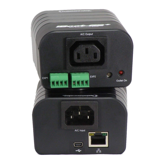
Page 5: Hardware Installation
4. Hardware Installation 4.1. Ethernet Connections iBoot-G2+ supports 10/100 Ethernet using the cable supplied, or other suitable unshielded twisted pair (Cat 5) cabling. Link (amber) and Activity (green) LEDs on the network connector indicate when the network connection is properly established. 4.2. - Page 6 4.3. Expansion Connections iBoot-G2+ has two Expansion Ports, Exp1 and Exp2 for connection to iBoot-Exp, or for use as General Purpose Inputs and Outputs (GPIO). Mode settings on the iBoot-G2+ determine how the expansion ports function. Connections to the iBoot-Exp are made using screw terminal blocks. The screw terminal blocks are on removable connectors for easy cable fabrication.
- Page 7 USB Serial Port (COMn) Used as General Purpose I/O The USB port can now be used with a standard Terminal Client (like HyperTerminal) to communicate directly with the iBoot-G2+. Dataprobe also provides a simple terminal program (EZ Term) at http://dataprobe.com/support/iboot.html V110120E...
- Page 8 4.5. Mounting Options iBoot-G2+ is suitable for desktop or shelf mounting. A mounting kit for wall and DIN rail mounting is available. Order part: 1920033 Mounting Kit for iBoot-G2+ G2 Series Remove all cables from the unit prior to installing or removing any mounting hardware.
-
Page 9: Initial Configuration
Install and Run the DMU 1. Download DMUSetup.exe 2. Run DMUSetup.exe 3. Run the DMU DMU Discovers Dataprobe Devices on Local Network Note: The IP address can only be set within the first two minutes of powering up the iBoot. The Setup Utility will only work with iBoots on the same local subnets as the PC. - Page 10 5.1. Other ways to set the IP Address 1. Automatically from a DHCP Server 2. Web Browser via the Set-up Page 3. CLI (Telnet & USB) iBoot-G2+ comes with factory installed IP address 192.168.1.254. Setting the IP address from a DHCP Server A DHCP server will automatically assign an IP address (dynamic address) as well as Subnet Mask and Gateway to the iBoot.
-
Page 11: Web Browser Operation
6. Web Browser Operation 6.1. Password Protection iBoot-G2+ uses two username/password credential sets, one for normal power control (User) and one that also provides access to the setup functions (Admin). Default Credentials: Role Username (fixed) Password (user set) Administrator admin admin User user... - Page 12 its original condition. To abort a power cycle, select the desired outlet and click on either Power On or Power Off buttons. iBoot-G2+ will assume the status selected. Expansion Set for Independent I/O Mode: The Control and Status page will display the Main Outlet, with power control buttons underneath.
-
Page 13: Web Setup
7. Web Setup iBoot-G2+ setup section consists of several pages. Access any page via the buttons on the left of the page. Each time a setting is changed click on the Save button for that page to save the changes before moving to the next page. - Page 14 Telnet Port: This setting is used to allow access to the iBoot-G2+ via telnet by ports other than standard 23. DxP Port: This setting is used to allow access to the iBoot-G2+ via Dataprobe Exchange Protocol (DxP) via ports other than standard 9100.
- Page 15 7.4. AutoPing AutoPing feature allows iBoot-G2+ automatically detect failed equipment and perform a timed reboot or other power control function (like turning on an indicator or siren). You set up to four IP addresses to be periodically pinged. When iBoot- G2+ no longer detects a response from these addresses, the programmed power control function is actuated.
- Page 16 Action: Select from None AutoPing not used Power On – Latch Upon triggering, iBoot-G2+ will power on and remain so until changed via the web, telnet, DxP, etc. Power On – Follow Upon triggering, iBoot-G2+ will power on. When the ping response returns, iBoot-G2+ will power off.
- Page 17 7.6. Heartbeat Like AutoPing, the Heartbeat monitor allows iBoot-G2+ to automatically detect failures in critical devices. With the Heartbeat monitor enabled, iBoot-G2+ will expect a message, either from the USB port or network on a regular interval. When it misses a user defined number of intervals, it will perform its programmed action.
- Page 18 Heartbeat feature has been triggered. A counter reset button is provided when logging in with the System password. 7.9. Using the Heartbeat Program The heartbeat program and instructions are available at http://dataprobe.com/support/iboot.html V110120E iBoot-G2+ Page 18...
- Page 19 7.10. Event Scheduling iBoot-G2+ can schedule up to eight reoccurring power events. Set the starting date and time, plus the action to be taken and any repeat cycle for each. To enable the time scheduling function: Enter an accessible Network Time Server and check the Enable box.
-
Page 20: Command Line Interface
The syntax of the CLI uses a basic Set (change a variable) and Get (retrieve a variable). The CLI is accessed either through the Telnet protocol, which requires a Telnet client program, or via USB which requires a serial communications program like Hyperterminal. Dataprobe also provides a simple terminal program (EZ Term) at http://dataprobe.com/support/iboot.html. - Page 21 Device Commands Set commands are available to the administrator only get location This command returns the iBoot-G2’s location ID. New Boot set location <20 char. max> This command is used to set the iBoot-G2’s location ID. set upgrade enable <yes | no> Enables or disables the ability to upload new firmware to the iBoot-G2.
- Page 22 CLI will protect against all 3 from being set to 0. set dxp control <enable/disable> This command allows the main and expansion ports to Disabled be controlled using Dataprobe Exchange Protocol (DxP) commands. set dxp query <enabled/disable> This command allows the status of the main and...
- Page 23 Action: Cycle Outlet: Exp2 Ok iBoot> set autoping <1a | 1b | 2 | 3> ipaddress This command is used to set the IP address of 0.0.0.0 <dotted decimal> AutoPing 1 or AutoPing 2 set autoping <1a | 1b | 2 | 3> frequency This command is used to set the frequency, in <1-999>...
- Page 24 Name Date Time Repeats Action 1. Event Name mm/dd/yyyy hh:mm Annually Power On 2. Event Name mm/dd/yyyy hh:mm Annually Power On 3. Event Name mm/dd/yyyy hh:mm Annually Power On 4. Event Name mm/dd/yyyy hh:mm Annually Power On 5. Event Name mm/dd/yyyy hh:mm Annually Power On 6. Event Name mm/dd/yyyy hh:mm Annually Power On 7. Event Name mm/dd/yyyy hh:mm Annually Power On 8. Event Name mm/dd/yyyy hh:mm Annually Power On set time server <dotted decimal> This command is used to set the IP Address of a 64.90.182.55 network time server. set time enable <yes | no> This command enables or disables the use of the time server and scheduled events.
-
Page 25: Dxp Protocol
9. DxP Protocol iBoot-G2+ supports the Dataprobe Exchange Protocol (DxP) for inter device communications and to allow software developers to integrate Dataprobe product into custom applications. Through the DxP protocol, the developer can: • Turn on and off power to the Main and Expansion Outlets or External Outputs •... -
Page 26: Troubleshooting
Troubleshooting The iBoot-G2+ has a recessed pushbutton switch in the event the unit is not performing as expected. Use the pushbutton as follows: Action Result Momentary Soft Reset. Will not change outlet status. 5 Seconds push Reset to Factory Defaults. Hold the button in until the Outlet LED is blinking, then release. -
Page 27: Specifications
Specifications 12.1. Physical 2.0” 60mm 8.6 oz 244g Height Weight 3.2” 82mm 320,000 hours Width MTBF 4.2” 107mm 0 – 50 degrees C Depth Temperature 12.2. AC Input IEC 320 C14 Input Cord 16AWGX3C 10A 250 UL/CSA/VDE Rated (1.25mm2X3C) Voltage Range Auto Sensing 105-240 VAC Switched Receptacle IEC 320 C13... -
Page 28: Technical Support And Warranty
Technical Support and Warranty Dataprobe Technical Support is available 8:30AM to 5:30PM ET to assist you in the installation and operation of this product. To obtain Technical Support call 201- 934-5111, or Email us at tech@dataprobe.com. Please have the following information available when you call: •...
Need help?
Do you have a question about the iBoot G2+ and is the answer not in the manual?
Questions and answers