Table of Contents
Advertisement
RSS Series
Redundancy Switch Systems
Installation and Operation
1. GENERAL
Dataprobe's RSS Redundancy Switch Systems provide high density relay based A/B switching for multiple
circuits. Two chassis systems are available to accommodate large and small applications.
Each system uses the same plug in cards, providing switching for up to 32 circuits in a single chassis. Both
systems offers gang (simultaneous) switching as well as individual control of each A/B card.
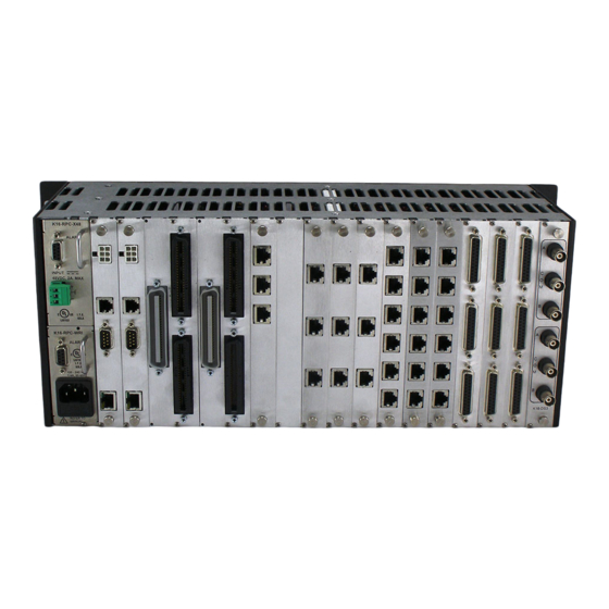
Dataprobe's RSS Series rack mounting chassis are available in two models; RSS-16 and RSS-3.
The RSS-16 supports up to 16 AB switch cards, 2 control interface cards and 2 internal power supply modules
in a compact 4U high, 19 inch chassis.
The RSS-3 supports up to 3 AB switch cards, 1 control interface card and 1 internal power supply module, in a
1U chassis with removable rack mount brackets.
Both chassis also provides access to local control switches for each of the A/B switch cards and viewing of their
A/B status LEDs.
Information in this manual applies to both systems except where specifically indicated.
Power Supply modules are available for 100 -240 VA/C , 50-60Hz and 48 VDC power sources. Two modules
can be installed in the chassis. In addition, external 24 V dc power supplies are available as an alternative to
the internal power module or to provide redundant power.
Advertisement
Table of Contents


Need help?
Do you have a question about the RSS-16 and is the answer not in the manual?
Questions and answers