
Subscribe to Our Youtube Channel
Related Manuals for MIMAKI JFX200-1213 EX


Summary of Contents for MIMAKI JFX200-1213 EX
- Page 1 You can also download the latest manual from official website. MIMAKI ENGINEERING CO., LTD. https://mimaki.com/ D203431-30 Original instructions...
- Page 2 TABLE OF CONTENTS Introduction .................. 6 For safe use.................. 8 Symbols .................... 8 Usage Warnings and Precautions ............ 9 Cautions on Installation .............. 15 Warning Labels................ 16 Chapter 1 Before Use 1.1 Usage Restrictions.............. 22 Usage Restrictions................ 22 User Restrictions ................ 22 Area Restrictions ................
- Page 3 Chapter 2 Basic Operation 2.1 Operation flow................. 54 2.2 Turning the Power On/Off............ 55 Turning the power on................ 55 Turning Off the Power................. 55 2.3 Setting up the Media............... 57 Setting up the Media................ 57 2.4 Repositioning the UV-LED Unit .......... 60 UV-LED unit position ................
- Page 4 3.14 Machine Settings .............. 98 AUTO Power-off Settings .............. 99 Time Settings.................. 99 Unit Settings .................. 100 Key Buzzer Settings ................. 101 Language Settings................ 102 Network Settings................ 103 External Stop I/F ................ 104 3.15 Nozzle Check Menu............ 106 Nozzle Check Menu List .............. 106 Printing Nozzle Check Flow..............
- Page 5 4.6 Consumable Item Replacement ........... 154 Replacing the wiper ................ 154 Replacing Carriage Filters .............. 155 Disposing the Waste Ink .............. 156 Replacing the waste ink tank before the waste ink tank confirmation message is displayed (1) .............. 159 Replacing the waste ink tank before the waste ink tank confirmation message is displayed (2) ..............
- Page 6 Adobe, the Adobe logo, Acrobat, Illustrator, Photoshop, and PostScript are the trademarks or registered trademarks of Adobe Incorporated in the United States and other countries. RasterLink and TxLink are trademarks or registered trademarks of Mimaki Engineering Co. Ltd. in Japan and other countries.
- Page 7 Introduction • Move the TV or radio away from this machine. • Plug the TV or radio into a power outlet on a power circuit other than the power circuit to which this machine is connected.
- Page 8 For safe use For safe use Symbols In this document, symbols are used for explaining the contents of cautions on operation. The symbol to be displayed differs depending on the caution content. Please understand the meaning of each symbol and use this machine safely and correctly.
- Page 9 If used as it is, it may cause fire or electric shock. Check first that the machine no longer produces smoke, and contact your distributor or a sales office of MIMAKI for repair. • Never repair your printer by yourself since it is very dangerous to do so.
- Page 10 For safe use • Precautions regarding ink are indicated on the Ink bottle. Read these carefully and make sure you understand the contents before using the product. • Store ink bottles and the waste ink tank in a location that is out of the reach of children. •...
- Page 11 Doing so will cause the paint to peel off.) • Always use only a LED UV device and UV power supply unit recommended by Mimaki. The use of any product other than our recommended products may lead to fire or machine damage.
- Page 12 For safe use • Use the printer in a room with as little dust as possible. • Keep children away from this machine. • If dust adheres around the head, it may cause ink droplets to fall. Execute head cleaning. •...
- Page 13 Handling the antifreeze liquid • Use the antifreeze liquid recommended by Mimaki. There is a risk of cooling device failure if other antifreez liquids is used. Malfunctions caused due to the use of other anti freezing liquids is out of the scope of warranty, and our company does not assume any responsibility for the same.
- Page 14 For safe use • When handling the anti freezing liquid, be sure to wear the included safety glasses and gloves. • Be sure to store the antifreeze liquid in a cold and dark place. Also keep it out of the reach of children.
- Page 15 For safe use • Using the printer in a place exposed to water will increase the possibility of electric leakage. Avoid using the printer in places exposed to water. Electrical leakage may lead to electric shock of personnel or fire. •...
- Page 16 Warning Labels Warning Labels As shown below, variouswarning labels are attached to the machine. Make sure you fully understand the details indicated on the various warning labels. If any of the warning labels become dirty and illegible or peel off, contact your local dealer or our service office and request new warning labels.
- Page 17 Warning Labels JFX200-1213EX Affixed below the cableveyor.
- Page 18 Warning Labels Order code Label M909381 M903330 M906115 M902663 M905980 M916117 (JFX200-2513EX) M919315 (JFX200-1213EX) M909385...
- Page 19 Warning Labels Order code Label M903281 M907935 M919473 (JFX200-1213EX only) M907764 (JFX200-1213EX CAUTION only) ATTENTION DO NOT STEP ON TOP NE GRIMPEZ PAS DESSUS...
- Page 20 Warning Labels...
- Page 21 Chapter 1 Before Use This chapter This chapter describes information essential before use, such as part names and installation methods. Usage Restrictions ..........22 Connecting the Cables ........3 4 Usage Restrictions ........22 Connecting the USB Cables ......3 4 User Restrictions........
- Page 22 • Access to the hazardous area must be prohibited for all persons except those who have received safety training from Mimaki Engineering or persons who have received training from them. If an untrained person enters the restricted area while the machine is in operation, there is a risk of accidental contact with the Y-bar that is in the process of printing, resulting in injury.
- Page 23 Chapter 1 Before Use 1.2 Installing this Machine Installation Environment • Do not use in a dusty place. It may lead to problems in the printer or poor printing. • For stable printing, use this machine in an environment with a temperature in the range of +15 ℃ to +30 ℃...
- Page 24 Chapter 1 Before Use • If you usually use photographic fixers, refrain from installing this machine in a room filled with the steam of photographic fixers. If this machine is installed in a room filled with photographic fixers, the ink adhering to the head solidifies and the image quality degrades no matter how many times the head is cleaned, or the nozzles may get clogged.
- Page 25 Chapter 1 Before Use 1.3 Avoid These While Operating the Printer Doing the things mentioned below when the printer is in operation might result in an injury. l Keep your face, hands, and all other body parts at a safe distance from the carriage area.
- Page 26 Chapter 1 Before Use l Keep your face, hands, and all other body parts at a safe distance from moving parts. • Do not bring your face, hands, or any other body parts close to or into the Y-bar belt. l Keep your face, hands, and all other body parts at a safe distance from the cable carrier section, and do not place any objects on top.
- Page 27 Chapter 1 Before Use l Do not look directly at the UV-LED. • Avoid looking directly at the UV-LED. Take special care when working while seated as the carriage will be roughly at eye level. Also, you may burn yourself from the LED UV unit and the parts around it, that have turned hot.
- Page 28 Chapter 1 Before Use l Pay attention to following when replacing the ink • To prevent the ink from sticking to your hands or eyes when it splashes, be sure to wear the included safety glasses and gloves. • Do not pull the ink cover too much. Pulling it too much might damage the tubes and cables.
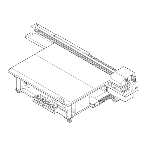
- Page 29 Chapter 1 Before Use 1.4 Names of Parts and Functions Front Side of this Machine illustration: JFX200-2513EX Power button Turns on/off the power to this machine. Carriage The carriage is provided with the ink heads for printing. Waste ink tank Waste ink gathers in this tank.
- Page 30 Chapter 1 Before Use Rear Side and Right Side of this Machine illustration: JFX200-2513EX Table Set the media on it. There are suction holes on the table to absorb the media when the vacuum is turned on. Y-bar When printing starts, it moves along the top of the table.
- Page 31 Chapter 1 Before Use Operation Panel Use the operation panel to perform settings for printing or operate this machine. [ADJUST] key [VACUUM] key Performs the adjusting functions Press to attach the media on the such as drop position correction. table. [UP] key POWER Lamp [MAINT.] key...
- Page 32 Chapter 1 Before Use Carriage The carriage is provided with the heads for printing and LED UV unit. • Do not look at the light emitted from the LED UV with a naked eye when lit. • Do not touch the LED UV unit when the LED is lit or just after it is set off. You may suffer serious burns, as the unit is very hot.
- Page 33 Chapter 1 Before Use Stop Switch Press the switch when you want to stop the machine for security reasons. There is one stop switch on the front side of the machine, and one each on the left and right edge of the Y- bar.
- Page 34 Chapter 1 Before Use 1.5 Connecting the Cables Connecting the USB Cables Connect this machine to the PC using a USB 2.0 interface cable. • Your RIP must be compatible with the USB 2.0 interface. • If the USB 2.0 interface isn't attached to the PC, contact your nearest RIP manufacturer or our sales office.
- Page 35 Chapter 1 Before Use When the machine is connected to the personal computer to which an external HDD is connected via USB, the speed of data output to the machine may drop. This may cause the head unit to stop temporarily at the right or left end during printing.
- Page 36 Chapter 1 Before Use Connecting a LAN Cable Observe the following precautions when connecting the LAN cable. • Make sure you push it in firmly until you hear a clicking sound. • Do not plug or unplug the cable while data is being transferred. LAN cable Printing Data via a Network If you want to print data via a network, you must construct the network in the following environment.
- Page 37 Chapter 1 Before Use l Connecting through switching hubs Printing cannot be done unless the PCs and devices connected to the printer are 1000BASE-T. After connecting, check the following: 1. Check the printer screen display. – From the LOCAL screen or MEDIA DETECT screen, press the [ENTER] key several times to display the information screen.
- Page 38 Chapter 1 Before Use 1.6 Ink Bottles Types of Usable Inks Following inks can be used with this machine. 4-color + white + clear model Uses one bottle each of cyan, magenta, yellow, and black and two bottles each of clear and white (LUS-150, LH-100, LUS-120, LUS-350, LUS-211) 4-color + white + clear + primer model...
- Page 39 Chapter 1 Before Use • Make sure that the lid is closed tightly before shaking the bottle. • Be careful while shaking the bottle, because the ink may leak to outside if you shake the bottle too hard. • If only a small amount of ink is remaining, it may not be possible to stir it properly. Hence, to stir the ink properly, tilt the ink bottle until it becomes vertical.
- Page 40 Chapter 1 Before Use Ink type Cap type • LUS150 ink Cap A • Primer ink Cap B • LUS-120 ink • LH-100 ink • LUS-350 ink • LUS-211 ink • LUS150 ink [Cap C] • LH100 ink • Primer ink •...
- Page 41 Chapter 1 Before Use Use the tightening jig to tighten the bottle cap in place. Tightening jig [SPA-0232] Good example Bad example Position the upper arrow within this range! [SPA-0328] Good example Bad example Position the upper arrow within this range! •...
- Page 42 Chapter 1 Before Use • Never rotate the ink bottle after setting it over the tank. Doing so may result in ink leakage. Lever Turn the tank lever from right to left. Insert the Ink IC chip. • Insert the Ink IC chip with its metal part on the left. Inserting an Ink IC chip with its wrong side inward may damage the Ink IC chip or cause it to malfunction.
- Page 43 Chapter 1 Before Use • The Ink IC chip has information on items such as ink color, remaining amount of ink, expiration date. When setting an ink bottle, insert the Ink IC chip included in the ink bottle package into the Ink IC chip insertion port provided on the ink cover. •...
- Page 44 Chapter 1 Before Use Lift the ink bottle vertically. • When the ink bottle is removed from the tank, make sure that the light-blocking cover is shut. • If the lid is not shut, close it manually. If the light-blocking cover is left open, the ink may harden.
- Page 45 Chapter 1 Before Use Keep the bottle in an upright position and remove any ink adhering to the cap surface by using a disposable wipe such as KimWipe. Remove the cap from the used ink bottle. • If the cap is hard to remove, use the fastening jig to remove it. Set a new ink bottle.
- Page 46 Chapter 1 Before Use If the light-blocking cover comes off When the light-blocking cover comes off, light penetrating into the tank may cause the ink to harden. Perform the following steps to reattach the light-blocking cover: Insert the light-blocking cover (one nub) into the cover insertion hole on the tank. While pressing the cover into the cap insertion hole as explained in Step 1, insert the other nub into the other insertion hole.
- Page 47 Chapter 1 Before Use Ink bottle lamp status Description No error Blinks in red Only a small amount of ink is remaining (near end) or the ink is one month past its expiration date. It needs to be replaced soon. Lights in red Ink bottle cannot be used either because it is empty or because of some ink error.
- Page 48 • Do not shake the ink bottle too vigorously. Vigorous shaking may cause the ink to leak from the bottle. • Never refill an ink bottle. This may cause malfunction. Mimaki bears no responsibility for problems caused by such refilling.
- Page 49 Chapter 1 Before Use 1.7 Media Usable media sizes and notes for handling are described below. Usable media sizes Item name JFX200-2513EX JFX200-1213EX Maximum width 2500 mm 1270 mm Maximum length 1300 mm 1300 mm Maximum print 2500 mm 1270 mm width Thickness 50 mm or less...
- Page 50 Chapter 1 Before Use • As the board surface is made of multiple boards, the board joints may get reflected in the printed image depending on the media thickness or strength of the paper. Also, vacuum holes may affect the printed images in the same way.
- Page 51 Chapter 1 Before Use 1.8 Notes Regarding Work Environment, etc. The frequency of configuring print settings and conducting maintenance is largely influenced by the work environment in which printing is performed and the conditions of the used media. Make sure that you have completely understood the following items before using this machine.
- Page 52 Chapter 1 Before Use...
- Page 53 Chapter 2 Basic Operation This chapter This chapter describes preparations of ink/media for printing, procedures before printing and settings. Operation flow ..........54 Test printing............6 4 Examples of Plotting Failure ......6 4 Turning the Power On/Off .......55 Relation between the head layout and the Turning the power on .........
- Page 54 Chapter 2 Basic Operation 2.1 Operation flow Turn power On/Off "Turning the Power On/Off"(P. 55) Set up the Media "Setting up the Media"(P. 57) Repositioning the UV-LED Unit "Repositioning the UV-LED Unit"(P. 60) Test Printing "Test printing"(P. 64) Head cleaning "Head Cleaning"(P.
- Page 55 Chapter 2 Basic Operation 2.2 Turning the Power On/Off Turning the power on Press the power button. • Press the power button located on the left side of the operation panel. Power button • When the power is turned on, the firmware version is displayed. JFX200EX Start-up Ver 1.00...
- Page 56 Chapter 2 Basic Operation Press the power button to turn off the power. • The power button lamp goes off. • When using this machine again, press the power button and wait until the green lamp is lit. Power button Precautions on turning off the power l Do not pull out the power cord from the power outlet.
- Page 57 Chapter 2 Basic Operation 2.3 Setting up the Media This machine can be used with a leaf media. For usable media, see "Usable media sizes"(P. 49) Setting up the Media • If a suction hole within the suction area is not covered by the media, lay out a thin sheet material such as paper, film or tape to cover the hole.
- Page 58 Chapter 2 Basic Operation Suction Area The following figure shows the suction area. Origin sticker Print origin Provided at the four corners of the table. • To change the point of origin, see "Changing the Point of Origin"(P. 74).
- Page 59 Chapter 2 Basic Operation Media Guide Holes The table edges (both top and bottom) are provided with guide holes for inserting the layout pins provided with the printer. Use these guide holes to keep the media straight. • A commercially available M3 screw can be used instead of the positioning pin provided with the printer.
- Page 60 Chapter 2 Basic Operation 2.4 Repositioning the UV-LED Unit Loosen the screws on both sides of the carriage and slide the UV-LED unit as needed for the colors and spot colors you wish to print. • Keep foreign matter out of the grooves on either side of the carriage where the UV-LED unit slides.
- Page 61 Chapter 2 Basic Operation l 4-color, W, CL (When using LUS-150, LH-100, LUS-120, LUS-350) Layer Layer Printing UV-LED Unit Position (mm) Single layer 2-layer 2nd layer: 1st layer: 2nd layer: 1st layer: 2nd layer: 1st layer: 2nd layer: 0 2nd layer: 1st layer: 65 1st layer: 2nd layer:...
- Page 62 Chapter 2 Basic Operation l 4-color, W, CL, Pr Layer Layer Printing UV-LED Unit Position (mm) Single layer 2-layer 2nd layer: 1st layer: 2nd layer: 1st layer: 2nd layer: 1st layer: 2nd layer: 0 2nd layer: 1st layer: 65 1st layer: 2nd layer: 1st layer: 2nd layer: 65...
- Page 63 Chapter 2 Basic Operation l 6-color, W, CL Layer Layer Printing UV-LED Unit Position (mm) Single layer 2-layer 2nd layer: 1st layer: 2nd layer: 1st layer: 2nd layer: 1st layer: 2nd layer: 0 2nd layer: 1st layer: 65 1st layer: 2nd layer: 1st layer: 3-layer...
- Page 64 Chapter 2 Basic Operation 2.5 Test printing Print the test pattern to make sure that there are no ink discharge problems such as clogged nozzle (blurred print or missing nozzles). Examples of Plotting Failure Discharge failure of the head (head nozzle) due to dust is a typical example of plotting failure. Periodically check the condition of the nozzle before output or during output to avoid using it in defective state.
- Page 65 Chapter 2 Basic Operation Relation between the head layout and the test patterns The following figure shows the relation between head layout and the positions of the printed test pattern. Head 1 Head 2 Head 3 ● 4C + 4SP Head 1 Head 2 pattern...
- Page 66 Chapter 2 Basic Operation Taking a Test Print Print the test pattern to make sure that there are no ink discharge problems such as clogged nozzle (blurred print or missing nozzles). The test pattern alignment direction can be selected for each test printing from the following two types. Select the direction suitable for your printing job.
- Page 67 Chapter 2 Basic Operation Press the [ENTER] key. • Start the test print. **PRINT** PLEASE WAIT • Once the printing is completed, the display returns to the Step 1. TEST PRINT (FEED DIR.) [ENT] Check the print results. • Under normal circumstances, the operations end here. •...
- Page 68 Chapter 2 Basic Operation 2.6 Head Cleaning Check the printed test pattern results and perform cleaning depending on the symptoms. Head cleaning can be done in three ways. Use them based on the pattern print results. Press the [CLEANING] key in LOCAL mode. CLEANING SOFT [ENT]...
- Page 69 Chapter 2 Basic Operation Run the test print again and check the print results. • Repeat the cleaning and test printing until the print results are normal. l If the image quality does not improve even after head cleaning • Clean the wiper and ink cap. "Cleaning wiper and cap"(P.
- Page 70 Chapter 2 Basic Operation 2.7 Printing the Data Starting a Printing Operation Set the media. • "Setting up the Media"(P. 57) (1) Open or close the suction valve according to the media size. (2) Press the [VACUUM] key to turn on the VACUUM lamp and adsorb the media. illustration: JFX200-2513EX Press the [REMOTE] key in LOCAL.
- Page 71 Chapter 2 Basic Operation • The media may get lifted and the print may get aborted due to the heat generated by the LED UV during printing. Reset the new media and start printing. Aborting a Printing Operation To stop printing halfway through, perform the following operations: Press the [REMOTE] key while printing.
- Page 72 Chapter 2 Basic Operation Press the key. VIEW SET VIEW POS Press the [ENTER] key. SET VIEW POS **** mm By pressing the keys, set the position to which the Y-bar is to be moved. • key: The Y-bar moves to the backside of the table with the point of origin in the center. •...
- Page 73 Chapter 3 Convenient Usage This chapter This chapter explains the operation procedures and various settings for convenient use of this machine. Changing the Point of Origin ......74 Ionizer Settings..........9 3 Using JOG Keys to Change the Print Origin AUTO CLEANING Settings ......9 4 ..............
- Page 74 Chapter 3 Convenient Usage 3.1 Changing the Point of Origin The factory setting of point of origin can be changed. It can be changed in one of the two ways. Changing with the JOG keys Changing from "ORIGIN" in the [FUNCTION] menu Media Light pointer mark...
- Page 75 Chapter 3 Convenient Usage Using FUNCTION menu to Change the Print Origin When setting an exact origin, set the X and Y coordinates of the origin from the FUNCTION menu. When the origin is set by using this option, the set value becomes the point of origin (0.0). Press the [FUNCTION] key in LOCAL.
- Page 76 Chapter 3 Convenient Usage 3.2 Registering the Media Thickness Register the thickness of the media to be set. You can register the thickness in the following three methods. • Registering the thickness manually • Selecting with [UP] [DOWN] keys • Checking the thickness automatically Registering the Media Thickness Manually Press the [FUNCTION] key in LOCAL.
- Page 77 Chapter 3 Convenient Usage Press the [ENTER] key. ORIGIN SETUP ORIGIN SETUP HEAD GAP = 1.2 MEDIA THICKNESS = *.* mm Automatic Checking of the Media Thickness Media thickness is automatically checked by the gap pin located at the center of the carriage. Set the media.
- Page 78 Chapter 3 Convenient Usage • Tolerance of the automatic thickness check is ±0.1 mm.
- Page 79 Chapter 3 Convenient Usage 3.3 HEAD GAP Value Set the head gap (height from media to head nozzle surface). When the head is to be moved onto the table for operations such as printing or maintenance, upon moving, it will maintain the head gap at the pre-set value. The upper limit of head gap varies depending on the thickness of the media.
- Page 80 Chapter 3 Convenient Usage Checking the Head Gap Value Perform the following operations when you want to check the currently set head gap value. Press the [ENTER] key in LOCAL. Press the [ENTER] key several times to display [HEAD GAP]. •...
- Page 81 Chapter 3 Convenient Usage 3.4 List of Functions This section outlines the various functions and describes their settings. About default "HOST" function • The value specified in the RIP software runs this function. When a value other than "HOST" is specified, the specified value is used instead of waiting for instructions from the RIP software.
- Page 82 Chapter 3 Convenient Usage 3.5 Adjusting the Bidirectional Print Drop Position If you change the printing conditions (such as media thickness and head height), do the following to correct the ink drop position for bidirectional printing (Bi) to acquire the proper printing results: Correcting the Drop Position Set the media and set the print origin.
- Page 83 Chapter 3 Convenient Usage Press to correct the drop position from pattern 1 onwards. • Corrected value: -40.0 to 40.0 PATTERN 1 • The position at which the outward feed line and the return feed line become one straight line is the correction value.
- Page 84 Chapter 3 Convenient Usage 3.6 Setting LOGICAL SEEK The head operations differ depending on the LOGICAL SEEK settings. • LOGICAL SEEK settings cannot be specified in RasterLink. When the machine setting is "HOST" the printing operation is performed considering that the LOGICAL SEEK is "ON". Media Machine width Head movement when...
- Page 85 Chapter 3 Convenient Usage Press to select the value to be set. • Available settings: HOST/ON/OFF LOGICAL SEEK : ON Press the [ENTER] key. SETUP LOGICAL SEEK [ENT] Press the [END] key several times to end the operation.
- Page 86 Chapter 3 Convenient Usage 3.7 Setting UV LEVEL Set the UV LED irradiation pattern to be used and illumination intensity to be maintained during printing. Press the [FUNCTION] key in LOCAL. FUNCTION VIEW [ENT] Press to select [SETUP], and press the [ENTER] key. SETUP DROP.POScorrect [ENT]...
- Page 87 Chapter 3 Convenient Usage Press to select the scanning direction, and press the [ENTER] key. • Available settings: Bi (bidirectional)/Uni (unidirectional) UV LEVEL : Bi Press to select the printing pattern, and press the [ENTER] key. • Available settings: PATTERN 1, 2, and onwards/NO PRINT •...
- Page 88 3.8 Reducing Stripes Between Passes MAPS Function If the feed lines do not disappear even after performing media feed correction, use the MAPS (Mimaki Advanced PassSystem) function to disperse the pass boundary to make the feed lines less visible. With this machine, you can use the MAPS2 function.
- Page 89 Chapter 3 Convenient Usage Press to select "AUTO" or "MANUAL". • AUTO: Settings are performed automatically according to the printing conditions. • MANUAL: Settings can be adjusted manually. MAPS 2 : MANUAL • If the feed stripes and uniformity of density are not improved by AUTO settings, adjust using MANUAL settings.
- Page 90 Chapter 3 Convenient Usage Press to set the [SPOT]. • AUTO: Patterns are set automatically depending on the printing conditions. • PATTERN 1 to 7/AUTO: The pattern that you select is printed. < SPOT > PATTERN: 1 Press the [ENTER] key. •...
- Page 91 Chapter 3 Convenient Usage Press to set the [TYPE/LV.]. • TYPE1 10 to 100%: Set a value according to the printing conditions. • TYPE2 10 to 100%: Set a value according to the printing conditions. < CLEAR TYPE/LV.: AUTO • The effects of MAPS2 differ depending on the images to be printed. Change print patterns, and check the effects in advance before using the MAPS2 function.
- Page 92 Chapter 3 Convenient Usage 3.9 WORK CHANGE Settings Set whether to return to LOCAL mode or keep the REMOTE mode after online plotting is complete. Press the [FUNCTION] key in LOCAL. FUNCTION VIEW [ENT] Press to select [SETUP]. FUNCTION SETUP [ENT] Press the [ENTER] key.
- Page 93 Chapter 3 Convenient Usage 3.10 Ionizer Settings Set the operations when the optional ionizer is installed. • These settings are not displayed if the optional ionizer is not installed. If this setting is not displayed even though the ionizer is installed, contact your local distributor, or our sales office or call center.
- Page 94 Chapter 3 Convenient Usage 3.11 AUTO CLEANING Settings You can set this function so that it counts the number of printed files or printed length after printing is complete, performs cleaning automatically if required. The machine can deliver stable output if its heads are always kept clean. Press the [FUNCTION] key in LOCAL.
- Page 95 Chapter 3 Convenient Usage Press to set a cleaning type. • Available settings: NORMAL/SOFT/HARD TYPE : NORMAL Press the [ENTER] key. Press the [END] key several times to end the operation. • Depending on the state of the head, there are cases in which the print defects are not corrected even after running this function.
- Page 96 Chapter 3 Convenient Usage 3.12 Setting Nozzle Surface Cleaning Frequency This function automatically cleans the nozzle face of the head and removes the ink droplets clinging to the nozzle face before or during printing. Press the [FUNCTION] key in LOCAL. FUNCTION VIEW [ENT]...
- Page 97 Chapter 3 Convenient Usage 3.13 Other Settings Change the settings according to the method of usage. Press the [FUNCTION] key in LOCAL. FUNCTION VIEW [ENT] Press to select [SETUP]. FUNCTION SETUP [ENT] Press the [ENTER] key. SETUP DROP.POScorrect [ENT] Press to select the item you want to set.
- Page 98 Chapter 3 Convenient Usage 3.14 Machine Settings These are various settings to help you use this machine comfortably. The following settings can be configured for the machine. Item Set value Details AUTO Power-off NONE/10 to 30 If are no operations or a set time, the to 600 min power turns off automatically.
- Page 99 Chapter 3 Convenient Usage AUTO Power-off Settings If are no operations or a set time, the power turns off automatically. Press the [FUNCTION] key in LOCAL. FUNCTION VIEW [ENT] Press to select [MACHINE SETUP]. FUNCTION MACHINE SETUP [ENT] Press the [ENTER] key twice. AUTO Power-off 30min Press...
- Page 100 Chapter 3 Convenient Usage Press to select [TIME]. MACHINE SETUP TIME [ENT] Press the [ENTER] key. TIME 2018.10.05 21:30:00 Press to enter time. • Selecting Year/Month/Day/Time: Select using • Inputting Year/Month/Day/Time: Input using Press the [ENTER] key. • The entered time is displayed. TIME 2018.10.05 15:30:00...
- Page 101 Chapter 3 Convenient Usage Press the [ENTER] key. TEMP. : °C [ENT] Press to select a unit for temperature. • Available settings: °C/°F Press the [ENTER] key. LENGTH : mm Press to select a unit for length. • Available settings: mm/inch Press the [ENTER] key.
- Page 102 Chapter 3 Convenient Usage Press to select "ON" or "OFF". KEY BUZZER : OFF Press the [ENTER] key. MACHINE SETUP KEY BUZZER [ENT] Press the [END] key several times to end the operation. • Even if the key buzzer is turned "OFF" the buzzer sounds for errors/warnings/completed operations cannot be turned off.
- Page 103 Chapter 3 Convenient Usage Press the [ENTER] key. MACHINE SETUP LANGUAGE [ENT] Press the [END] key several times to end the operation. Network Settings Press the [FUNCTION] key in LOCAL. FUNCTION VIEW [ENT] Press to select [NETWORK] and press the [ENTER] key. MACHINE SETUP NETWORK [ENT]...
- Page 104 Chapter 3 Convenient Usage Press , and press the [ENTER] key. • [AutoIP] is selected. NETWORK AutoIP Press to select a setting, and press the [ENTER] key. • Available settings: ON/OFF • If set to "ON", the IP address to be used is set according to the AutoIP protocol. However, if DHCP is "ON", DHCP takes priority.
- Page 105 Chapter 3 Convenient Usage Press the [FUNCTION] key in LOCAL. FUNCTION VIEW [ENT] Press to select [MACHINE SETUP]. FUNCTION MACHINE SETUP [ENT] Press the [ENTER] key. MACHINE SETUP AUTO Power-off [ENT] Press to select [EXE I/F]. MACHINE SETUP EXE I/F [ENT] Press the [ENTER] key.
- Page 106 Chapter 3 Convenient Usage 3.15 Nozzle Check Menu This configures the operations related to Nozzle Missing check function. Nozzle Check Menu List Item Set value Details Printing Check ON/OFF Set this to on if you want to perform nozzle check when "Printing Nozzle Check Settings"(P.
- Page 107 Chapter 3 Convenient Usage Retry → judgment If more missing nozzles than the "Judgment Condition" are detected after the recovery operation, the recovery operation is re-run. – This applies if the "RETRY COUNT" is set to 1 or more. Auto nozzle recovery → judgment If more missing nozzles than the "Judgment Condition"...
- Page 108 Chapter 3 Convenient Usage Press to select "ON" and press the [ENTER] key. • Available settings: ON/OFF • Select "OFF" to disable Printing Nozzle Check. Printing Check Press the [ENTER] key, and select [CHECK INTERVAL]. Printing Check :Check Interval Press to select the setting item and press the [ENTER] key.
- Page 109 Chapter 3 Convenient Usage Press to select the setting value and press the [ENTER] key. • Available settings: 0 to 3 RETRY COUNT Press the [END] key to end the operation. Auto Nozzle Recovery Settings Press the [FUNCTION] key in LOCAL. FUNCTION VIEW [ENT]...
- Page 110 Chapter 3 Convenient Usage Press to select [Judgment Condition]. NOZZLE CHECK : Judgment Condition Press to select the setting value and press the [ENTER] key. • Available settings: 1 to 64 • Each time you press the [ENTER] key, the target color changes. •...
- Page 111 Chapter 3 Convenient Usage 3.16 Resetting to Default Settings The details set in [SETUP] [MAINTENANCE] and [MACHINE SETUP] are returned to factory default settings. Press the [FUNCTION] key in LOCAL. FUNCTION VIEW [ENT] Press to select [MACHINE SETUP]. FUNCTION MACHINE SETUP [ENT] Press the [ENTER] key.
- Page 112 Chapter 3 Convenient Usage 3.17 Confirming Machine Information You can check the information of this machine. The following items can be checked as the machine information. Item Details USAGE WIPING This displays the usage status of the machine. "Checking Machine Usage PRINT LENGTH Status"(P.
- Page 113 Chapter 3 Convenient Usage WASTE INK TANK Displays how full the waste ink tank is WASTE INK TANK UV LAMP Displays the usage time of UV lamps 1 and 2 UV LAMP 1: LED A USE TIME Displays the total power on time USE TIME Checking Version Information Press the [FUNCTION] key in LOCAL.
- Page 114 Chapter 3 Convenient Usage Displaying other information Press the [ENTER] key in LOCAL. ***INK MMCCYYKK REMAIN 99999999 Each time you press the [ENTER] key, subsequent details are displayed in order. • The following information is displayed. • Remaining amount of ink BTL.
- Page 115 Chapter 3 Convenient Usage Stopping the circulation/agitation operation while power is off When white ink is used in the machine, start up the machine periodically to perform the circulation/agitation operation to prevent the ink from settling. (during operation, the remaining time is indicated at the bottom of the display) Circulating Agitating...
- Page 116 Chapter 3 Convenient Usage...
- Page 117 Chapter 4 Maintenance This chapter This chapter explains the necessary items for comfortable use of this machine, such as methods of daily maintenance and ink cartridge maintenance. Daily maintenance .........118 Automatic Maintenance Function ....1 51 Precautions for maintenance ....118 Setting the refresh intervals .......
- Page 118 Chapter 4 Maintenance 4.1 Daily maintenance Conduct the machine maintenance periodically or depending on the operation frequency of the machine, in order to use it for a long time while maintaining its accuracy. Precautions for maintenance Pay attention to the following items when maintaining this machine. •...
- Page 119 Chapter 4 Maintenance Maintenance timing Maintenance timing Maintenance items (reference page) Daily (after one day of work) "Maintenance of Head Surroundings"(P. 134) "Cleaning wiper and cap"(P. 122) "Cleaning the NCU"(P. 128) Twice a week "Washing the Head Nozzle (When Using the PR-200 Ink)"(P.
- Page 120 Chapter 4 Maintenance Maintenance of Machine Exterior Depending on the usage environment, trash and dust may stick to the exterior of the main unit. To prevent dust from entering the head moving part, soak a soft piece of cloth in water, wring it tightly and then wipe off the dust.
- Page 121 Chapter 4 Maintenance MBIS maintenance Please replace the Bottle Wiping Filter (PN: SPC-0820) if it gets dirty. Remove the bottle wiping filter. Bottle wiping filter Attach a new Bottle Wiping Filter (PN: SPC-0820). LM guide cleaning When the LM guide gets dirty, wipe it off with a soft, dry cloth. •...
- Page 122 Chapter 4 Maintenance 4.2 Maintaining the Capping Station Maintain the ink cap and wiper in the capping station. (STATION MAINT.) The ink cap and wiper function as described below. • Wiper: Wipes off any ink on the head nozzle • Ink cap: Prevents the clogging of head nozzles due to dryness As you use this machine, the wiper and ink cap start getting dirty from ink and dust.
- Page 123 Chapter 4 Maintenance Press the [ENTER] key. • Carriage moves onto the table. Moving carriage Remove the wiper. • Pull out the wiper by holding the protrusions at both the ends. Protrusion Clean the wiper and the bracket. • Wipe off any ink on the wiper and the bracket using a clean stick soaked in washing liquid. Wipe it off properly so that there is no residual washing liquid.
- Page 124 Chapter 4 Maintenance • Clean it until it looks like the picture. • After cleaning, make sure the wiper and bracket are aligned horizontally.
- Page 125 Chapter 4 Maintenance Clean the wiper cleaner. • Clean the tip of the wiper cleaner with a clean stick. Wiper cleaner • Lift the wiper cleaner up and clean the ink adhering to the inside with a clean stick. • Clean around the wiper cleaner. •...
- Page 126 Chapter 4 Maintenance Return the wiper to its original position. • Insert the wiper by holding both the ends. Protrusion Clean the cap rubber and cap rubber cover. • Wipe off any ink on the cap rubber and the cap rubber cover using a clean stick soaked in washing liquid.
- Page 127 Chapter 4 Maintenance Press the [FUNCTION] key in LOCAL. Press to select [MAINTENANCE]. Press the [ENTER] key twice. • This will put the machine in the same state as when you press the [MAINT.] key in LOCAL.
- Page 128 Chapter 4 Maintenance Cleaning the NCU Ink and dust adhere to the NCU. The NCU cannot operate normally if there is ink or dust adhering to it. Press the [MAINT.] key in LOCAL. CARRIAGE OUT [ENT] Press the [ENTER] key. MOVE POSITION : STATION MAINT.
- Page 129 Chapter 4 Maintenance Station Area Cleaning We recommend that you clean the machine often to maintain the quality of the machine and the images. • Clean the area around the station twice a week (frequency of cleaning differs depending on the usage frequency of the printer).
- Page 130 Chapter 4 Maintenance Wipe off any ink on the flushing unit or the shutter. • Wipe off the ink using a clean stick soaked in washing liquid. Wipe it off properly so that there is no residual washing liquid. Flushing filter Flushing unit Shutter •...
- Page 131 Chapter 4 Maintenance Take washing liquid in a dropper and fill the cap with it until it is full. • Fill the cap with washing liquid until it is about to overflow. Press the [ENTER] key. • After the dry suction operation is performed for 30 seconds, the display returns to Step 2. DISWAY WASH PLEASE WAIT When the Machine Is Not Used For a Long Time...
- Page 132 Chapter 4 Maintenance Clean the wiper and the bracket. (1) Pull out the wiper by holding the protrusions at both the ends. (2) Use a clean stick soaked in washing liquid. • Wipe it off properly so that there is no residual washing liquid. (3) Hold the wiper by the protrusions at both the ends and push it back to the original position.
- Page 133 Chapter 4 Maintenance • [COMPLETED (NEXT): ENT] is displayed on the screen until the washing liquid is filled. Press the [ENTER] key after Step 8 is complete. If you press the [ENTER] key before the washing liquid is filled, the carriage returns to its original position. Take washing liquid in a dropper and fill the cap with it until it is full.
- Page 134 Chapter 4 Maintenance 4.3 Maintenance of Head Surroundings Extremely minute mechanisms are used for the head, and therefore proper care must be taken when performing maintenance. Some gel-like ink or dust may be stuck in the bottom part of the slider and around the head. Rub it off using a clean stick or another similar tool.
- Page 135 Chapter 4 Maintenance Wipe any ink on the sides of the head and carriage using a clean stick. • Never rub the nozzle part. Clean the side of the Nozzle part (Never touch) head (dark gray part) with a clean stick. Clean using a clean stick.
- Page 136 Chapter 4 Maintenance 4.4 When Nozzle Clogging Cannot Be Solved If the nozzle clogging is not resolved even after head cleaning "Head Cleaning"(P. 68) is implemented, execute the following functions. HEAD FILLUP • Fill the head with ink. Filling with ink from the sub tank to the head NOZZLE WASH •...
- Page 137 Chapter 4 Maintenance Washing of head nozzle Wash the head nozzle to prevent them from getting clogged due to the hardened ink. Check these items in advance Is [INK END] displayed? • The ink is absorbed during washing. If the ink end is detected at this time, washing cannot be performed.
- Page 138 Chapter 4 Maintenance • [COMPLETED (NEXT): ENT] is displayed on the screen until the cleaning of the cap is complete. Press the [ENTER] key after Step 6 is complete. If you press the [ENTER] key before the cleaning is complete, the machine moves to the next washing step.
- Page 139 Chapter 4 Maintenance Press the [ENTER] key. • This will absorb the washing liquid filled in the cap. • The screen on the right is displayed while the cleaning liquid is still left in the cap. • After the duration has passed, the display returns to Step 2. PLEASE WAIT **CLEANING** 00 : 00...
- Page 140 Chapter 4 Maintenance Press the [ENTER] key. • Carriage moves. WIPER CLEANING COMPLETED (NEXT) [ENT] • [COMPLETED (NEXT): ENT] is displayed on the screen until the cleaning work of wiper is complete. Press the [ENTER] key after Step 4 is complete. If you press the [ENTER] key before the cleaning is complete, the machine moves to the next washing step.
- Page 141 Chapter 4 Maintenance Clean the cap rubber and cap rubber cover. • Wipe off any ink on the cap rubber and the cap rubber cover using a clean stick soaked in the F-200/LF-200 Maintenance Liquid. Thoroughly wipe off, ensuring there is no residual F-200/ LF-200 Maintenance Liquid.
- Page 142 Chapter 4 Maintenance Execute head cleaning (HARD) once for the head equipped with PR-200. (1) Press the [END] key to display the LOCAL screen. (2) Press the [CLEANING] key, then press to select CLEANING: HARD, and press the [ENTER] key. (3) In SELECT HEAD, press to select only Head 3, and press the [ENTER] key.
- Page 143 Chapter 4 Maintenance Open the maintenance cover. Maintenance cover • After the work is complete, quickly attach the removed cover. If you leave it removed for a long time, ultra-violet rays may affect the ink. Press the [ENTER] key. SET TOOL COMPLETED [ENT] •...
- Page 144 Chapter 4 Maintenance 6-Color + W Y Lm Cl W Cl W K Lc • Turn the cap 30° counterclockwise and then remove it. • Ink is stuck on the removed cap. Temporarily place it on a paper towel, etc. to avoid contamination of the surrounding area.
- Page 145 Chapter 4 Maintenance Press the [ENTER] key. AIR PG. START [ENT] Release the colored ink or the air mixed in the ink. • When you press the [ENTER] key, the machine goes into a state of atmospheric release and the ink comes out vigorously.
- Page 146 Chapter 4 Maintenance • After the work is complete, quickly attach the removed cover. If you leave it removed for a long time, ultra-violet rays may affect the ink. NOZZLE RECOVERY Function If nozzle clogging cannot be improved at the specified points, other good nozzles can be used as alternatives (nozzle recovery) for printing.
- Page 147 Chapter 4 Maintenance Press the [ENTER] key to start printing. • The nozzle pattern is printed. • When you select [ENTRY] in Step 2, the machine moves to the nozzle line selection step (Step 5) without printing the nozzle pattern. **PRINT** PLEASE WAIT •...
- Page 148 Chapter 4 Maintenance Target for nozzle recovery No registration No registration Press the [END] key several times to end the operation. • Up to 10 nozzles can be registered for each nozzle line. • Time required for printing does not change even if you use this function. •...
- Page 149 Chapter 4 Maintenance Select [NOZZLE RECOVERY] of the MAINTENANCE menu. (1) Press the [FUNCTION] key in LOCAL. (2) Press to select [MAINTENANCE], and press the [ENTER] key. (3) Press to select [NOZZLE RECOVERY]. (4) Press the [ENTER] key. Press to select [CHECK BEFORE PRINT], and press the [ENTER] key. NOZZLE RECOVERY : CHECK BEFORE PRINT Press...
- Page 150 Chapter 4 Maintenance Press the [ENTER] key. Press the [END] key several times to end the operation.
- Page 151 Chapter 4 Maintenance 4.5 Automatic Maintenance Function To use this machine comfortably, you can set the various maintenance functions to be run automatically. Here, set performing intervals of various automatic maintenance functions. Issues such as ink clogging can be avoided by performing automatic maintenance periodically. (Automatic maintenance function) For automatic maintenance function, you can make the following settings.
- Page 152 Chapter 4 Maintenance Press the [ENTER] key. AUTO MAINT. REFRESH [ENT] Press the [END] key several times to end the operation. Setting the Cleaning Interval Cleaning type and the interval between each cleaning operation are set. Select [AUTO MAINT.] of the MAINTENANCE menu. (1) Press the [FUNCTION] key in LOCAL.
- Page 153 Chapter 4 Maintenance Press the [END] key several times to end the operation.
- Page 154 To order replacement consumable items, contact your local dealer or our service office. For more information on consumable items, refer to our website. https://mimaki.com/supply/inkjet.html Replacing the wiper The wiper is a consumable good. If the message on the right is displayed, replace the wiper as soon as possible.
- Page 155 Chapter 4 Maintenance Insert a new wiper • Insert the wiper by holding the protrusions at both the ends. Protrusion Press the [ENTER] key. • After its initial operation, the machine returns to LOCAL. *Being Initialized* PLEASE WAIT Replacing Carriage Filters Replace the filters once every 1 or 2 weeks.
- Page 156 Chapter 4 Maintenance Install the new carriage filter (PN : SPC-0851). New carriage filter • Carriage filters are on the left, right, and back side of the carriage. Replace all the filters at same time. Once the replacement is complete, press the [ENTER] key. Disposing the Waste Ink The ink used in head cleaning and other functions is stored in the waste ink tank on the lower right side of the machine.
- Page 157 Chapter 4 Maintenance Disposing of Waste Ink • When disposing of the waste ink from the waste ink tank, be sure to wear the included safety glasses and gloves. Otherwise you may get ink in your eyes. • Do not replace the waste ink tank while this machine is in operation (printing or cleaning). •...
- Page 158 Chapter 4 Maintenance Replace the waste ink tank. (1) Prepare a new waste ink tank. (2) Insert by holding the handle of the waste ink tank. (3) Lift the waste ink tank and check that it is set just below the drain port. Rail •...
- Page 159 Chapter 4 Maintenance Replacing the waste ink tank before the waste ink tank confirmation message is displayed (1) When replacing the waste ink tank before the waste ink tank confirmation message is displayed (before reaching 80% (2.1 L) of the 2.6 L tank), set the waste ink information to 0% on the INFORMATION menu. Empty the waste ink tank.
- Page 160 Chapter 4 Maintenance Replacing the waste ink tank before the waste ink tank confirmation message is displayed (2) Set the waste ink information to 0% in the MAINTENANCE menu. Empty the waste ink tank. • "Disposing of Waste Ink"(P. 157) Press the [FUNCTION] key in LOCAL.
- Page 161 Chapter 4 Maintenance 4.7 About Refilling the Cooling Water To cool the LED UV unit, put anti freezing liquid mixed with water into the cooling water tank in the cooling device. The water and anti freezing liquid (PN : SPC-0394) ratio should be 2 (water) to 1 (antifreeze). Cooling device l Notes on refilling •...
- Page 162 Chapter 4 Maintenance l Precautions for handling antifreeze liquid • Always use an anti freezing liquid recommended by Mimaki. The cooling device may malfunction if any other product is used. (Supplied antifreeze liquid: 1000 cc x 1) • Do not touch the antifreeze liquid directly. If you accidentally touch the antifreeze liquid, wash it off immediately with soap and water.
- Page 163 Chapter 4 Maintenance Remove the water supply/drainage cap and air purge cap. Water supply/ drainage Air purge Prepare mixed water solution (antifreeze liquid:1, water: 2) in the provided container and fill it into the provided syringe. Fill the mixed water solution until the buzzer sound stops. •...
- Page 164 Chapter 4 Maintenance 4.8 Flushing Filter Tools required for • F-200/LF-200 Washing Liquid (PN : • Safety glasses replacement SPC-0568) • Waste cloth • Gloves • Be sure to wear the included safety glasses and gloves when performing replacement. As there is ink absorbed in the flushing filter, it may get in your eyes. Replacing the Flushing Filter The flushing filter needs to be replaced periodically.
- Page 165 Chapter 4 Maintenance Replacing the flushing filter before the replacement message is displayed Select [STATION MAINT.] of the MAINTENANCE menu. (1) Press the [ENTER] key in LOCAL. (2) Press to select [MAINTENANCE], and press the [ENTER] key. (3) Press to select [STATION MAINT.]. (4) Press the [ENTER] key.
- Page 166 Chapter 4 Maintenance...
- Page 167 Chapter 5 Troubleshooting This chapter Check again before deciding the trouble as malfunction. Troubleshooting..........168 If the message "SHAKE WHITE INK Power does not turn on ......168 BOTLES" is displayed........ 1 70 Machine does not start printing ....168 If an error related to the sub tank occurs ... 1 71 Image quality is poor ........
- Page 168 Chapter 5 Troubleshooting 5.1 Troubleshooting Check again before deciding the trouble as malfunction. If there is no improvement even after troubleshooting, contact your local distributor, or our sales office or call center. Power does not turn on In most of the cases, the power does not turn on due to improper connection of the power cable for the machine or the computer.
- Page 169 Chapter 5 Troubleshooting Problem Solution Clean around the head. "Maintenance of Head Surroundings"(P. 134) Execute head cleaning [NORMAL]. "Head Cleaning"(P. 68) Set a shorter interval for the interval wiping operation. "Setting Nozzle Surface Cleaning Frequency"(P. 96) Nozzle is clogged Nozzle discharge may become unstable depending on the surrounding temperature or if the machine is not used for a long time.
- Page 170 Chapter 5 Troubleshooting Perform the following operation to check the details of the ink bottle error. Press the [ENTER] key in LOCAL mode. LUS-150 CMWWYKClCl REMAIN 34567899 Press the [ENTER] key. NON INK IC CMWWYKClCl • Details of the ink bottle error are displayed. •...
- Page 171 Chapter 5 Troubleshooting • Make sure that the lid is closed tightly before shaking the bottle. • The ink may leak outside if you shake the bottle too hard. Shake carefully. • If only a small amount of ink is remaining, it may not be possible to stir it properly. To stir it properly, tilt the ink bottle until it becomes vertical.
- Page 172 Chapter 5 Troubleshooting Press the [ENTER] key. SELECT SUBTANK :CMYKYKMCClClWW Press the [ENTER] key. SUB TANK EXECUTE [ENT] Press the [ENTER] key. • Automatic discharge and filling operations are performed. **FILL UP** PLEASE WAIT • Perform cleaning once the filling is complete. **CLEANING** PLEASE WAIT Press the [END] key several times to end the operation.
- Page 173 Chapter 5 Troubleshooting Rotate the adjustment screw of the throttle valve to release it so that air can flow. • Rotate the adjustment screw of the throttle valve until it comes to the middle position. Adjustment screw for positive pressure Turn the adjustment screw to this position Adjustment screw for negative pressure...
- Page 174 Chapter 5 Troubleshooting 5.2 Problems Causing Messages to Appear When an abnormality occurs, the buzzer rings and the display shows a corresponding message. Take measures according to the message. Warning message Errors when performing operations Message Cause Corrective action CAN'T OPERATE An ink error occurred.
- Page 175 Chapter 5 Troubleshooting Message displayed in LOCAL Message Cause Corrective action <LOCAL> Multiple ink errors • Press the [ENTER] key to (unusable ink). check the ink bottle generating CAN'T PRINT/CART. [ENT] the error and the error details. Ink supply (printing, Replace the ink bottle with a cleaning) cannot be usable one.
- Page 176 Chapter 5 Troubleshooting Message Cause Corrective action <LOCAL> Liquid level sensor • Turn off the power on the abnormality of the sub machine and turn it on after a SUB TANK: CMYKYKMCClClWW tank has been detected. while. If displaying again, contact your local distributor, our sales office, or service center.
- Page 177 Chapter 5 Troubleshooting Message Cause Corrective action INK COLOR The color of ink in the ink • Check the color of the ink bottle bottle is of a different for which the warning occurred. : ---- YYKK type than the currently supplied ink.
- Page 178 Chapter 5 Troubleshooting Message Cause Corrective action ERROR 128 • Data transmission speed is too fast. HDC FIFO OVER • Control circuit board is defective. ERROR 128 • Data transmission speed is too slow. HDC FIFO UNDER • Control circuit board is defective.
- Page 179 Chapter 5 Troubleshooting Message Cause Corrective action ERROR 186 Error detected in the print waveform. HDC OVERFLOW ERROR 186 HDC UNDERFLOW ERROR 187 HDC SLEW RATE ERROR 188 HDC MEMORY ERROR 18a Error occurred in the main PCB power supply. Main PCB V_CORE ERROR 18b Error occurred in the 1.5...
- Page 180 Chapter 5 Troubleshooting Message Cause Corrective action ERROR 403 An error due to excessive current of X X CURRENT motor was detected. ERROR 404 An error due to excessive current of Y Y CURRENT motor was detected. ERROR 444 Time to replace the •...
- Page 181 Chapter 5 Troubleshooting Message Cause Corrective action If displaying again, contact your local distributor, our sales office, or service center. ERROR 61c Abnormality in the • Adjust the pressure. starting of negative "If pressure abnormality NEGATIVE P.CONTROL pressure control. occurs"(P. 172) If displaying again, contact your ERROR 61d Negative pressure...
- Page 182 Chapter 5 Troubleshooting Message Cause Corrective action ERROR 65c • Replace the NCU if the error NCU Sens Adj Err L does not clear. Contact your local dealer or our service office. ERROR 702 The thermistor is • Turn off the power on the defective.
- Page 183 Chapter 5 Troubleshooting Message Cause Corrective action ERROR 90f • ERROR 920 Ambient temperature is • Adjust the ambient temperature MACHINE TEMP./L **°C outside the allowable of the place where the machine range (low). is installed. ERROR 924 Ambient temperature is MACHINE TEMP./H **°C outside the allowable range (high).
- Page 184 Chapter 5 Troubleshooting...
- Page 185 Chapter 6 Appendix This chapter contains the lists of the specifications and functions of this machine. Specifications ..........186 Order of Ink Bottles ........1 89 Machine specifications ......186 Inquiry Sheet ..........1 90 Ink Specifications ........187 LICENSE Library ..........1 91...
- Page 186 Chapter 6 Appendix 6.1 Specifications Machine specifications Item JFX200-2513EX JFX200-1213EX Print head Type On-demand piezo head Specifications 3-head: 2 staggered, color 2 in-line, special color 1 in-line Print conditions 4-color + White + 300 × 300HQ: Bidirectional/Unidirectional 4/8 pass (scan × feed) Clear 300 ×...
- Page 187 Chapter 6 Appendix Item JFX200-2513EX JFX200-1213EX Noise levels During standby Not exceeding 55 dB (FAST-A, 1 m on all sides) Continuous Not exceeding 75 dB operation Compliance with standards VCCI Class A, FCC Class A, UL62368-1 ETL compliance, CE marking (EMC Directive, Low Voltage Directive, Machinery Directive), IEC/EN62368-1 (CB certified), RoHS compliant, REACH compliant, RCM Power supply specifications...
- Page 188 1 to 60°C (storage permitted only for 120 hours or less if the temperature is 60°C and one month or less if the temperature is 40°C) • Do not use any ink other than the MIMAKI designated ink. Also, do not disassemble the ink bottles or refill or replenish their ink.
- Page 189 Chapter 6 Appendix 6.2 Order of Ink Bottles The order of the set ink bottles differs depending on the ink set used. For JFX200-2513EX For JFX200-1213EX Ink set Ink distribution 4-color + white ink + clear 4-color + white ink + primer + clear 4-color + white ink(OPT-J499 required) 6-color + white ink + clear...
- Page 190 Chapter 6 Appendix 6.3 Inquiry Sheet Use this sheet for inquiries regarding printer malfunctions and abnormal operations. Fill in the following required fields and fax the sheet to our sales office. Company Name Contact Personnel Name Contact No. Printer Model Name Your OS Machine Information Error message...
- Page 191 Chapter 6 Appendix 6.4 LICENSE Library Mimaki printer Firmware Copyright @2020 MIMAKI ENGINEERING CO.,LTD. All rights reserved. This product contain open source software listed in the tables below. Component License StarterWare for ARM® based TI Sitara Processors BSD-TI The following license terms and conditions shall apply to the open source software listed in the table above: BSD-TI Copyright (C) 2010 Texas Instruments Incorporated - http://www.ti.com/...
- Page 192 Chapter 6 Appendix...
- Page 193 JFX200-2513EX / JFX200-1213EX Operation Manual October, 2024 MIMAKI ENGINEERING CO.,LTD. 2182-3 Shigeno-otsu, Tomi-shi, Nagano 389-0512 JAPAN D203431-30-17102024...
- Page 194 © MIMAKI ENGINEERING CO., LTD.2019 FW : 3.0...
Need help?
Do you have a question about the JFX200-1213 EX and is the answer not in the manual?
Questions and answers