Table of Contents
Advertisement
Quick Links
DRV830x Rev D. Hardware Quick Start Guide
Version 1.0.5
Motor Solutions
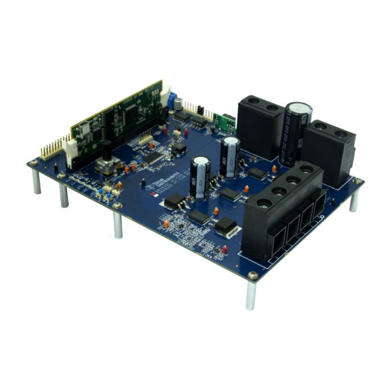
Fig 1: DRV830x EVM with controlCARD
Abstract
The Low Voltage, High Current Motor Drive EVM (DRV8301, Figure 1), provides a great way to
learn and experiment with digital control of sub 60 volt three-phase motors to increase efficiency
of operation. The board is available in two configurations, the DRV8301 or the DRV8302. This
document goes over the typical kit contents and hardware details, and explains the functions and
locations of jumpers and connectors present on the board. This document supersedes all the
documents available for the kit.
1
Advertisement
Table of Contents

Related Manuals for Texas Instruments DRV830x Rev D.


Summary of Contents for Texas Instruments DRV830x Rev D.
- Page 1 DRV830x Rev D. Hardware Quick Start Guide Version 1.0.5 Motor Solutions Fig 1: DRV830x EVM with controlCARD Abstract The Low Voltage, High Current Motor Drive EVM (DRV8301, Figure 1), provides a great way to learn and experiment with digital control of sub 60 volt three-phase motors to increase efficiency of operation.
- Page 2 Version: 1.0.5 Revision History: 1.0.5 April 23, 2014 Fixed page 18-20 comments regarding ADC and IQ CURRENT, VOLTAGE, and pole settings 1.04 January 29, 2014 Changed page 8 regarding GPIO to Enable Pin connection with TMDSCNCD28027F 1.03 July 11, 2013 Updated for TMDSCNCD28027F support.
- Page 3 WARNING This EVM is meant to be operated in a lab environment only and is not considered by TI to be a finished end-product fit for general consumer use This EVM must be used only by qualified engineers and technicians familiar with risks associated with handling high voltage electrical and mechanical components, systems and subsystems.
-
Page 4: Table Of Contents
Table of Contents Getting Familiar with the Kit ......................5 Kit Contents ....................................5 Board Features: ..................................5 Warning: about low switching frequencies on the DRV830x ....................5 Hardware Overview ........................6 Macro Blocks .................................... 6 Powering the Board ......................... 8 Hardware Resource Mapping ...................... -
Page 5: Getting Familiar With The Kit
Getting Familiar with the Kit Kit Contents The DRV830x EVM is usually available packaged as a full solution kit: • MCU controlCARD • DRV830x EVM board with slot for the controlCARD • USB Cable • USB/DVD with CCStudio IDE, GUI, documentation, and link to project software distribution •... -
Page 6: Hardware Overview
voltage level for the high-side gate driver. A bootstrap capacitor under voltage protection circuit (BST_UVP) will start under this circumstance to prevent the potential failure of the high-side MOSFET. In this circumstance, both the FAULT and OTW pins should pull low and the device should self-protect itself. - Page 7 Fig2: DRV830x-EVM Board Macros...
-
Page 8: Powering The Board
Powering the Board The board is separated into two power domains*, the low voltage Controller Power domain that powers the controller and the logic circuit present on the board, and the medium voltage power delivery line that is used to carry the medium voltage and current like the DC power for the Inverter also referred to as DC Bus. -
Page 9: Hardware Resource Mapping
6. Connect an 8-60V DC power supply to the PVDD and GND terminals. Fig3: DRV830x-HC-EVM Motor Connections Hardware Resource Mapping Resource Allocation Function GPIO Signal Name Pin no. (DRV8301/DRV8302) GPIO-00 PWM_AH DRV830x Phase AH PWM input GPIO-01 PWM_AL DRV830x Phase AL PWM input GPIO-02 PWM_BL DRV830x Phase BH PWM input... - Page 10 GPIO-13 OCTWn Over-temperature warning GPIO-14 FAULTn Over-current fault GPIO-15 LED-2 User LED GPIO-16 SPI-SIMO Isolated SPI Interface GPIO-17 SPI-SOMI Isolated SPI Interface GPIO-18 SPI-CLK Isolated SPI Interface GPIO-19 SPI-STE Isolated SPI Interface GPIO-20 QEPA Encoder A GPIO-21 QEPB Encoder B GPIO-22 STATUS User LED...
-
Page 11: Jumpers And Connectors
ADC-A7 ADC-Vhb2 Phase Voltage sense B ADC-B0 Tach/Pot input ADC-B1 IB-FB Current sense phase B ADC-B2 VDCBUS DC Bus voltage sense ADC-B3 IA-FB Current sense phase A ADC-B4 ADC-Vhb3 Phase Voltage sense C ADC-B5 IB-FB Current sense phase B ADC-B7 ADC-Vhb1 Phase Voltage sense A Table 1: Signal mapping to the controlCARD DIMM slot... - Page 12 HEADER2x1 HEADER2x1 TERM BLOCK HEADER TERM BLOCK HEADER Table 2: List of Connectors...
- Page 13 J2 (User Power Access) J8 (User SPI) J13 (User Power Access) J21 (External JTAG) Pin # Signal Pin # Signal Pin # Signal Pin # Signal VCC_5V iSD-O VCC_3.3V iCLK-O TRSTn iSD-I J4 (Optional Encoder) iGPIO J20 (DRV8301 SPI)) Pin # Signal IGND Pin #...
- Page 14 Tables3-17 Individual Connector Pinouts J5 (External Controller Access) Pin # Signal Pin # Signal VCC_5V VCC_5V STATUS EN_GATE QEPA QEPI FAULTn QEPB CAP3 OCTWn DC_CAL CAP1 DAC_PWM1 CAP2 DAC_PWM3 DAC_PWM2 DACE_PWM4 PWM_CL PWM_AL PWM_BL PWM_AH PWM_CH PWM_BH ADC-Vhb1 ADC-Vhb2 ADC-Vhb3 IC-FB VDCBUS I_TOTAL...
- Page 15 Test Points Jumpers Test Point Net Connection Reference Function VCC_5V VCC_5V to controlCARD VCC_5V_R5 CAN termination PWRGD VCC_3.3V REF_1.65V PVDD TP10 TP11 VCC_5V TP12 SH_A TP13 SH_B TP14 SH_C TP15 TP16 IB-FB TP17 IA-FB TP18 U10_1 TP19 IC-FB TP20 IGND TP21 TP22 U11_1...
-
Page 16: Optimizing Sense Circuitry
Optimizing Sense Circuitry Overview Proper resolution of motor signals is critical to the performance of any control system, but especially those with software observers attempting to replace the precision of an absolute encoder. Because the DRV83xx are built to work at over 50 Vdc-bus, the resolution of the voltage sensing is not as precise as you would like for motors <... -
Page 17: Shunt Current Feedback
Shunt Current Feedback �� �� = 1.65 + �� ∙ �� ∙ ������ �� ������ ���� ��ℎ������ ���� �� �� − 1.65 3.3 − 1.65 Select resistor values to provide Vout = 3.3V for maximum peak-to-peak phase current = 16.5 ������... -
Page 18: Phase Voltage Feedback
o �� Update the current hardware resistors ��ℎ������ o �� = R107, R95; R108,R105; R113, R103 = R80, R81, R82 ������ o �� = R92, R94; R101, R104; R99, R102 ���� //! \brief Defines the maximum current at the input to the AD converter •... - Page 19 Ex: for a maximum of 12V, add headroom of 30% to set �� ������ ( 4.99 kΩ + �� �� • �� = �� ∙ to 15.6V ���� ������ ������ 4.99 kΩ �� ������ ( 4.99 kΩ + �� �� 15.6��...
-
Page 20: Phase Voltage Filter Feedback
Phase Voltage Filter Feedback • See 5.2.4 of the User’s Guide • The voltage filter pole is needed by the FAST estimator to allow an accurate detection of the voltage feedback. The filter should be low enough to filter out the PWM signals, and at the same time allow a high speed voltage feedback signal to pass through the filter •... - Page 21 //! \brief Defines the analog voltage filter pole location, Hz #������������ USER_VOLTAGE_FILTER_POLE_Hz (400.0)
-
Page 22: Schematic Disclaimer And Warnings
EVALUATION BOARD/KIT IMPORTANT NOTICE Texas Instruments (TI) provides the enclosed product(s) under the following conditions: This evaluation board/kit is intended for use for ENGINEERING DEVELOPMENT, DEMONSTRATION, OR EVALUATION PURPOSES ONLY and is not considered by TI to be a finished end-product fit for general consumer use. - Page 23 Mailing Address: Texas Instruments Post Office Box 655303 Dallas, Texas 75265 Copyright © 2012, Texas Instruments Incorporated FCC Warning This evaluation board/kit is intended for use for ENGINEERING DEVELOPMENT, DEMONSTRATION, OR EVALUATION PURPOSES ONLY and is not considered by TI to be a finished end-product fit for general consumer use.
-
Page 24: Important Notice
IMPORTANT NOTICE Texas Instruments Incorporated and its subsidiaries (TI) reserve the right to make corrections, enhancements, improvements and other changes to its semiconductor products and services per JESD46, latest issue, and to discontinue any product or service per JESD48, latest issue.
Need help?
Do you have a question about the DRV830x Rev D. and is the answer not in the manual?
Questions and answers