Table of Contents
Advertisement
Quick Links
www.ti.com
EVM User's Guide: DAC80516EVM
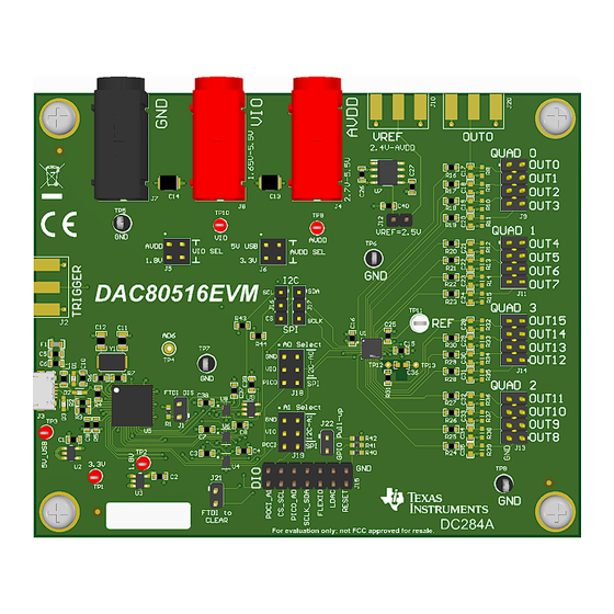
DAC80516 Evaluation Module
Description
The
DAC80516EVM
is an easy-to-use platform to
evaluate the functionality and performance of the
DAC80516
device. The DAC80516EVM has optional
circuits and jumpers to configure the device for
different applications. The DAC80516 is installed on
the EVM.
The DAC80516 offers 16 low power, 16-bit, buffered
voltage-output DACs with a full-scale output of 2.5V or
5V. The devices include a 2.5V internal reference. The
DAC output range is programmable to 2.5V or 5V.
Getting Started
1. Order the
EVM.
2. Configure EVM jumpers.
3. Install the DAC805xxEVM GUI from ti.com.
4. Connect USB and external power supplies.
5. Launch the DAC805xxEVM GUI.
SLAU916 – MAY 2024
Submit Document Feedback
Features
•
Configurable circuit to evaluate the DAC80516
•
Onboard AVDD (5V or 3.3V) and VIO (1.8V, 3.3V,
or 5V) support via USB and on-board voltage
regulators
•
Option for external reference voltage or on-board
2.5V reference voltage
•
Trigger output is available for synchronous
measurement
•
On-board FT4232 used to easily write to DAC
using the DAC805xxEVM GUI
•
External SPI and I
Applications
•
Optical networking
•
Wireless infrastructure
•
Industrial automation
•
Data acquisition systems
Copyright © 2024 Texas Instruments Incorporated
Description
2
C connections available
DAC80516 Evaluation Module
1
Advertisement
Table of Contents

Related Manuals for Texas Instruments DAC80516EVM


Summary of Contents for Texas Instruments DAC80516EVM
- Page 1 • Onboard AVDD (5V or 3.3V) and VIO (1.8V, 3.3V, DAC80516 device. The DAC80516EVM has optional or 5V) support via USB and on-board voltage circuits and jumpers to configure the device for regulators different applications.
-
Page 2: Kit Contents
This user's guide describes the characteristics, operation, and recommended use cases of the DAC80516EVM. This document provides examples and instructions on how to use the DAC80516EVM board and included software. Throughout this document, the terms evaluation board, evaluation module, and EVM are synonymous with the DAC80516EVM. -
Page 3: Hardware Theory Of Operation
C protocols. 2.1.1 Hardware Theory of Operation The DAC80516EVM is connected to the computer through the on-board FT4232 digital controller using the USB cable that is supplied with the EVM. The evaluation board features connectors and test points for all communication lines, DAC outputs, digital pins, and supplies. -
Page 4: Jumper Definitions
Hardware www.ti.com 2.1.2 Jumper Definitions The jumpers must be connected properly to operate the DAC80516EVM. Table 2-1 provides the details of the configurable jumper settings of the DAC80516EVM. Figure 2-2 shows the default jumper connections on the board. Table 2-1. DAC80516EVM Jumper Definitions... -
Page 5: Connector Definitions
SMA connector for FT4232 trigger input (unpopulated) SMA connector for DAC80516 OUT0 (unpopulated) Table 2-4 shows output header J9, J11, J13, and J14 definitions for the DAC80516EVM. SLAU916 – MAY 2024 DAC80516 Evaluation Module Submit Document Feedback Copyright © 2024 Texas Instruments Incorporated... -
Page 6: Test Points
DAC80516 OUT13 DAC80516 OUT14 DAC80516 OUT15 2, 4, 6, 8 Ground 2.1.4 Test Points The DAC80516EVM has test points available for measuring and debugging purposes. Table 2-5 lists the description of each test point. Table 2-5. DAC80516EVM Test Points Test Point... -
Page 7: Hardware Overview
DAC80516 CS/SCL pin DAC80516 POCI/A1 pin 1,3,5,7,9,11,13 Ground 2.2.2 SPI Configuration Figure 2-3 shows the DAC80516EVM configured for SPI communication. Figure 2-3. DAC80516EVM SPI Configuration SLAU916 – MAY 2024 DAC80516 Evaluation Module Submit Document Feedback Copyright © 2024 Texas Instruments Incorporated... - Page 8 Hardware www.ti.com 2.2.3 I C Configuration Figure 2-4 shows the DAC80516EVM configured for I C communication. Figure 2-4. DAC80516EVM I C Configuration The jumper connections on J18 and J19 determine the device address of the DAC80516. The following table shows the required configuration of the A0 and A1 jumpers for specific device addresses.
- Page 9 A probe can be placed across TP12 and TP13. Figure 2-5 shows a glitch measurement taken with the DAC80516EVM. In this example, C36 was populated with a 10pF capacitor and the glitch was captured on the rising edge between codes 0x7FFF to 0x8000. Time (250ns/div) Figure 2-5.
-
Page 10: Software Installation
Figure 3-2 shows the FTDI USB drivers installation window that is automatically launched after the DAC805xxEVM software installation is complete. Figure 3-2. FTDI USB Drivers DAC80516 Evaluation Module SLAU916 – MAY 2024 Submit Document Feedback Copyright © 2024 Texas Instruments Incorporated... -
Page 11: Software Overview
C has been selected as the protocal. Select the CONFIG button to save the current settings and launch the main GUI. Figure 3-4. DAC8050xxEVM Interface Settings Menu SLAU916 – MAY 2024 DAC80516 Evaluation Module Submit Document Feedback Copyright © 2024 Texas Instruments Incorporated... -
Page 12: Software Features
C or SPI communication to the DAC80516. Although the entire register map is available for use, some features have been abstracted into user controls in the High-Level Configuration page for easy operation. DAC80516 Evaluation Module SLAU916 – MAY 2024 Submit Document Feedback Copyright © 2024 Texas Instruments Incorporated... - Page 13 DAC80516 - DACs tab of the High Level Configuration page. This tab is used to set the gain and output of the DACs. The internal reference can also be powered on and off here. SLAU916 – MAY 2024 DAC80516 Evaluation Module Submit Document Feedback Copyright © 2024 Texas Instruments Incorporated...
- Page 14 DACs, along with setting the configuration for the GPIO pin. Figure 3-9. DAC80516 CLEAR/GPIO Tab of the High Level Configuration Page DAC80516 Evaluation Module SLAU916 – MAY 2024 Submit Document Feedback Copyright © 2024 Texas Instruments Incorporated...
- Page 15 100nF DDBUS7 FTDI_SCL FTDI_SDA_OUT PWREN DUT_SDA 1.00M FTDI_SDA_IN SN74LVC1G07QDBVRQ1 SUSPEND FT4232H-56Q-TRAY TXU0304RUT 20pF 20pF AVDD SN74LVC1G07QDBVRQ1 100nF Figure 4-2. DAC80516EVM Schematic: FTDI Controller Interface SLAU916 – MAY 2024 DAC80516 Evaluation Module Submit Document Feedback Copyright © 2024 Texas Instruments Incorporated...
- Page 16 4.2 PCB Layouts Figure 4-3 through Figure 4-6 show the board layout for the DAC80516EVM. Figure 4-3. DAC80516EVM PCB Top Layer Layout Figure 4-4. DAC80516EVM PCB Ground Plane Layout DAC80516 Evaluation Module SLAU916 – MAY 2024 Submit Document Feedback...
- Page 17 Hardware Design Files Figure 4-5. DAC80516EVM PCB Power Plane Layout Figure 4-6. DAC80516EVM PCB Bottom Layer Layout SLAU916 – MAY 2024 DAC80516 Evaluation Module Submit Document Feedback Copyright © 2024 Texas Instruments Incorporated...
- Page 18 Hardware Design Files www.ti.com 4.3 Bill of Materials Table 4-1 lists the DAC80516EVM bill of materials. Table 4-1. Bill of Materials for the DAC80516EVM Designator Quantity Value Description Package Reference Part Number Manufacturer C1, C2, C5 4.7µF CAP, CERM, 4.7µF, 16V,+/- 10%, X7R, 0603 0603...
- Page 19 Hardware Design Files Table 4-1. Bill of Materials for the DAC80516EVM (continued) Designator Quantity Value Description Package Reference Part Number Manufacturer Header, 2.54mm, 4x2, J9, J11, J13, J14 Header, 2.54mm, 4x2, Gold, TH TSW-104-08-L-D Samtec Header, 2.54mm, 2x1, Header, 2.54mm, 2x1, Gold, TH...
- Page 20 Hardware Design Files www.ti.com Table 4-1. Bill of Materials for the DAC80516EVM (continued) Designator Quantity Value Description Package Reference Part Number Manufacturer TP11 Test Point, Compact, White, TH White Compact Testpoint 5007 Keystone Electronics White Miniature TP12 Test Point, Miniature, White, TH...
- Page 21 Hardware Design Files Table 4-1. Bill of Materials for the DAC80516EVM (continued) Designator Quantity Value Description Package Reference Part Number Manufacturer R8, R9, R10, R11, R12, R13, R14, R15, R32, R33, 0603 R34, R35, R36, R37, R38, R39 5002 SLAU916 –...
-
Page 22: Additional Information
Texas Instruments integrated circuits used in the assembly of the DAC80516EVM. This user's guide is available from the TI web site under literature number SLAU916. Any letter appended to the literature number corresponds to the document revision that is current at the time of the writing of this document. - Page 23 STANDARD TERMS FOR EVALUATION MODULES Delivery: TI delivers TI evaluation boards, kits, or modules, including any accompanying demonstration software, components, and/or documentation which may be provided together or separately (collectively, an “EVM” or “EVMs”) to the User (“User”) in accordance with the terms set forth herein.
- Page 24 www.ti.com Regulatory Notices: 3.1 United States 3.1.1 Notice applicable to EVMs not FCC-Approved: FCC NOTICE: This kit is designed to allow product developers to evaluate electronic components, circuitry, or software associated with the kit to determine whether to incorporate such items in a finished product and software developers to write software applications for use with the end product.
- Page 25 www.ti.com Concernant les EVMs avec antennes détachables Conformément à la réglementation d'Industrie Canada, le présent émetteur radio peut fonctionner avec une antenne d'un type et d'un gain maximal (ou inférieur) approuvé pour l'émetteur par Industrie Canada. Dans le but de réduire les risques de brouillage radioélectrique à...
- Page 26 www.ti.com EVM Use Restrictions and Warnings: 4.1 EVMS ARE NOT FOR USE IN FUNCTIONAL SAFETY AND/OR SAFETY CRITICAL EVALUATIONS, INCLUDING BUT NOT LIMITED TO EVALUATIONS OF LIFE SUPPORT APPLICATIONS. 4.2 User must read and apply the user guide and other available documentation provided by TI regarding the EVM prior to handling or using the EVM, including without limitation any warning or restriction notices.
- Page 27 Notwithstanding the foregoing, any judgment may be enforced in any United States or foreign court, and TI may seek injunctive relief in any United States or foreign court. Mailing Address: Texas Instruments, Post Office Box 655303, Dallas, Texas 75265 Copyright © 2023, Texas Instruments Incorporated...
- Page 28 TI products. TI’s provision of these resources does not expand or otherwise alter TI’s applicable warranties or warranty disclaimers for TI products. TI objects to and rejects any additional or different terms you may have proposed. IMPORTANT NOTICE Mailing Address: Texas Instruments, Post Office Box 655303, Dallas, Texas 75265 Copyright © 2024, Texas Instruments Incorporated...
Need help?
Do you have a question about the DAC80516EVM and is the answer not in the manual?
Questions and answers