Table of Contents
Advertisement
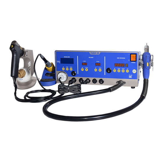
Rework System
Instruction Manual
Thank you for purchasing the HAKKO FR-702 Rework System.
Please read the manual before operating the HAKKO FR-702.
Keep this manual readily accessible for reference.
Table of Contents
...................................................................................... 1
.................................................................................. 2
......................................................................................... 63
.............................................................................. 69
●
●
................................................. 3
.............................................................. 4
............................................................ 5
................................................................. 5
............................................... 9
......................................................... 12
......................................... 13
................................................. 14
....................................................... 15
..................................................... 16
......................................................... 18
..................................... 27
.................................................... 35
............................................ 42
........................................................................ 43
...................................................................... 44
.......................................................................... 45
........................................................ 49
.......................................... 54
..................................................................... 57
............................................................ 58
........................................................... 59
...................................................................... 61
................................... 40
Advertisement
Table of Contents

Subscribe to Our Youtube Channel
Related Manuals for Hakko Electronics FR-702


Summary of Contents for Hakko Electronics FR-702
-
Page 1: Table Of Contents
Rework System Instruction Manual ● Thank you for purchasing the HAKKO FR-702 Rework System. Please read the manual before operating the HAKKO FR-702. Keep this manual readily accessible for reference. ● Table of Contents 1. PACKING LIST ..................1 2. SPECIFICATIONS .................. -
Page 2: Packing List
1. PACKING LIST Please check to make sure that all items listed below are included in the package. HAKKO FR-702 Station Tool box Power cord Handpiece holder (for hot air) HAKKO FX-8801 Soldering iron Pads (ø3.0 mm, ø5.0 mm, ø7.6 mm) -
Page 3: Specifications
2. SPECIFICATIONS ● HAKKO FX-8801 Power consumption 100V-1030W 110V-1170W Power consumption 65W (26V) 220V-1430W 230V-1530W 240V-1630W Tip to ground resistance < 2 Ω ● Station Tip to ground potential < 2 mV Dimensions (W × H × D) 370(W) × 150(H) × 220(D) mm Heating element Ceramic heater (14.6 ×... -
Page 4: Warnings, Cautions And Notes
● Use only genuine HAKKO replacement parts. ● Do not allow the HAKKO FR-702 to become wet, or use it when hands are wet. ● Be sure to hold the plug when inserting or removing the handpiece and power cords. -
Page 5: Part Names (Soldering Iron)
4. PART NAMES (Soldering iron) ● Station Power Switch (Main) Soldering Control Buttons Control Buttons (A.IRON) (B.IRON) Power Switch (A.IRON) Power Switch (B.IRON) Receptacle Receptacle (A.IRON) (B.IRON) Power cord receptacle Fuse ※Use this product with the following models. (Soldering iron) ・HAKKO FX-8801 ・HAKKO FX-8803 ・HAKKO FX-8805... -
Page 6: Initial Setup (Soldering Iron)
5. INITIAL SETUP (Soldering iron) A. Setup the iron holder Large sponge 1. Fit the small sponge pieces into the hollows of the iron holder base. 2. Add an appropriate amount of water into the iron Small sponge holder base. The small sponge will absorb water pieces and help keep the large sponge damp at all times. - Page 7 CAUTION Place the iron in the iron holder when not in use. Turn the power off when the HAKKO FR-702 is not in use for an extended period. B. After use Always clean the tip and coat it with fresh solder after use. (...
- Page 8 B. The preset mode The HAKKO FR-702 (Soldering iron) has a preset mode that will allow the unit to store up to 5 preset temperatures you can change between instead of using the above normal mode. Initial preset temperatures P1: 250℃ (482℉), P2: 300℃ (572℉), P3: 350℃ (662℉), P4: 400℃ (752℉), P5: 450℃ (842℉) The initial number of active presets is set to 5 at the factory.
- Page 9 D. Restriction on setting changes (Password function) It is possible to restrict certain setting changes to the unit. There are three choices for the password setting. (The factory default is "0 : Open") 0 : Open 1 : Partial 2 : Restricted Move to the parameter setting mode ○...
-
Page 10: Parameter Setting (Soldering Iron)
7. PARAMETER SETTING (Soldering iron) The HAKKO FR-702 (Soldering iron) has the following parameters. Parameter name Initial value Parameter No. Value ℃ ℃/F selection ℃ / ℉ ℃ Low temperature error setting 54 ~ 270℉ (30 ~ 150℃) Setting mode selection 0:... - Page 11 A. ℃ or ℉ temperature display selection 1. Either will be displayed if you press the button when is displayed. will be switched alternately If you press the button. 3. The display will return to if you press the button after selecting. B.
- Page 12 D. Password setting 1. Press the button to change the display to 2. If you press the button, the display will move to the setting mode selection screen. If you press the button, (Open), (Partial) and (Restricted) will be switched alternately.
-
Page 13: Maintenance (Soldering Iron)
8. MAINTENANCE (Soldering iron) Performing proper and periodic maintenance extends product life. Efficient soldering depends upon the temperature, quality and quantity of the solder and flux. Apply the following service procedure as dictated by the conditions of usage. WARNING Since the soldering iron can reach a very high temperature, please work carefully. Except the case especially indicated, always turn the power switch OFF and disconnect the power plug before performing any maintenance procedure. -
Page 14: Checking Procedure (Soldering Iron)
9. CHECKING PROCEDURE (Soldering iron) Disconnect the plug of the cord assembly and a. Between pins 4 & 5 2.5 – 3.5 Ω (Heating Element) (at time of room temperature) measure the resistance value between the ping of the connecting plug as follows. b. -
Page 15: Error Messages (Soldering Iron)
B. Broken Cord Assembly There are two methods of testing the cord assembly. 1. Turn the unit ON and set the temperature control knob to 480℃. Then bend the iron cord at various locations along its length, including in the strain CAUTION relief area. -
Page 16: Part Names (Desoldering Tool)
11. PART NAMES (Desoldering Tool) ● Station Power Switch (Main) Desoldering Control Buttons (Desoldering Tool) Receptacle Power Switch (Desoldering Tool) (Desoldering Tool) ● Handpiece (HAKKO FR-4101 Desoldering Tool) Back holder Filter pipe Assembly Nozzle Heating element (Inside) Release knob Trigger Hose Cord assembly... -
Page 17: Initial Setup (Desoldering Tool)
1. Connect the power cord to the receptacle on the it seats. rear of the station. 2. Connect the plug from the HAKKO FR-4101 to the receptacle on the HAKKO FR-702 (Desoldering tool). To disconnect, pull the plug CAUTION from the receptacle while Connect the plug to the receptacle, aligning the tab on the plug with the opening on the receptacle. - Page 18 3. Set the HAKKO FR-4101 in the handpiece holder. 4. Connect the hose from the HAKKO FR-4101 Connect the hose. to the vacuum outlet cap on the HAKKO FR-702 station. 5. Plug the power cord into a grounded power outlet.
-
Page 19: Operation (Desoldering Tool)
13. OPERATION (Desoldering Tool) ● Operation and indication Switch and control button Normal display screen - Moving the cursor UP. Increases the value. - Moving the cursor DOWN. Decreases the value. - End of sequence (terminates a phase of a data entry mode). - Page 20 Please wait for the heater to reach the set temperature. B. Making Changes to Settings ● Selecting the preset number The HAKKO FR-702 (Desoldering Tool) has a preset mode. 1. Press any of the three control buttons. 2. The preset selection screen appears.
- Page 21 ● Changing various settings (other than preset selections) 2. The setting selection screen 1. Press and hold any one appears. of the three control buttons Set Temp for at least 2 seconds. Offset Temp Vacuum Check <↑> <↓> <ENT> The following settings can be changed from this screen: Set Temp (Nozzle temperature setting) Offset Temp...
- Page 22 ● Set Temp CAUTION The temperature range is from 330 to 450℃. ( 620 to 850℉) ● If you enter a value outside the temperature setting range, the display returns to the hundreds digit, and you have to enter a correct value. 1.
- Page 23 ● Offset Temp Example:If the measured temperature is 405℃ and set temperature is 400℃, the difference is -5℃. (need to decrease by 5℃) So, enter the figure which 5 is deducted from present offset value. 1. Move the cursor to select “Offset Temp”. After selecting, press <ENT>. 380゚...
- Page 24 ● Vacuum Check During suction, the gauge indicating sucking status is shown at the lower side of the screen. C H K Suction gauge Sign of clogging When “CHK” appears and you notice that the sucking force is weakening, perform “Vacuum Check.” 1.
- Page 25 ● Preset Temp CAUTION The temperature range is from 330 to 450℃. ( 620 to 850℉) ● If you enter a value outside the temperature setting range, the display returns to the hundreds digit, and you have to enter a correct value. 1.
- Page 26 ● Preset ID CAUTION As a preset ID, 1 to 8 characters can be used. Usable characters are “A-Z,” “0-9,” and space (“ ”). Entering a space makes your entry terminated. Any character(s) that follows the space is deleted. 1. Move the cursor to select “Preset ID”. After selecting, press <ENT>. V a c u u m C h e c k P r e s e t T e m p...
- Page 27 ● LCD Contrast To make the screen display easy to see, adjust contrast. 1. Move the cursor to select “LCD Contrast”. After selecting, press <ENT>. P r e s e t T e m p P r e s e t L C D C o n t r a s t <↑>...
-
Page 28: Parameter Settings (Desoldering Tool)
14. PARAMETER SETTINGS (Desoldering Tool) ● PARAMETER SETTINGS Press and hold any one of the three control buttons, and turn on the power switch to display the parameter setting screen. The following parameters can be set: Parameter name Value Initial value ℃... - Page 29 ● ShutOff Set Select whether you will activate the auto shut off function. When the auto shutoff function is set to on and no operation is performed for constant time after the iron is set in the iron holder, the buzzer sounds three times and the auto shutoff function will be enabled.
- Page 30 ● Vacuum Mode Select whether you manually operate the desoldering pump or use the timer function. Normal:Solder is sucked only when you are pulling the trigger. Timer:Even after you release the trigger, sucking continues for the specified period of time. * Set time in “Vacuum Time.”...
- Page 31 ● Auto Sleep Select whether you will activate the auto sleep function. When the auto sleep function is set to on and no operation is performed for constant time after the iron is set in the iron holder, the auto sleep function will be enabled. * Set temp in “Sleep temp”.
- Page 32 ● Sleep Temp Sets the auto sleep temperature. 1. Move the cursor to select “Sleep Temp”. After selecting, press <ENT>. V a c u u mM o d e A u t o S l e e p 2. Entering from hundreds to units digit. S l e e p T e m p 200゚...
- Page 33 ● Error Alarm In the buzzer sound setting mode, which sets whether to sound the buzzer when a error occurs. 1. Move the cursor to select “Error Alarm”. 200゚ C S l e e p T e m p After selecting, press <ENT>. 150゚...
- Page 34 ● Pass. Lock When enabling this function, you must enter a correct password to change a setting. The options are as follows: Lock : All setting changes require a password entry. Partial : Selection of whether or not to enter a password when changing set temperature, preset selection, and offset temperature.
- Page 35 ● Initial Reset Initial Reset allows the factory default settings to be restored. 1. Move the cursor to select “Initial Reset”. After selecting, press <ENT>. R e a d y A l a r m P a s s . L o c k I n i t i a l R e s e t...
-
Page 36: Maintenance (Desoldering Tool)
15. MAINTENANCE (Desoldering Tool) Properly maintained, the HAKKO FR-702 desoldering tool should provide years of good service. Efficient desoldering depends upon the temperature, nozzle selection, and proper routine maintenance. Perform the following service procedures as dictated by the conditions of the station's usage. - Page 37 Nozzle Maintenance CAUTION The desoldering tool may be extremely hot. During maintenance, please work carefully. 1. Inspect and clean the nozzle ● Turn the power switch ON and let the nozzle Cleaning with the nozzle cleaning pin heat up. The cleaning pin passes completely through the CAUTION hole.
- Page 38 2. Disassemble the heating element. Remove the element cover assembly and the nozzle with the provided wrench. CAUTION The element cover assembly is held to The heating element is the nozzle changing very hot during operation. tool by pressing this part from both sides.
- Page 39 ① ② 5. Replacement of station filter If the filer is showing signs of stains from flux or is stiff, replace it. Filter Attach the filter as shown in the right Vacuum outlet cap Vacuum outlet cap diagram. (with Filter) Replacing the heating element (heating core) CAUTION Except the case especially indicated, always turn the power switch OFF and disconnect the...
- Page 40 Maintenance of the pump head ● Remove the cover When performing maintenance on the pump head, remove the screws holding the cover and take the cover off. Pump head ● Cleaning the pump head 1. Remove the valve and valve guard and remove any attached flux. CAUTION •...
-
Page 41: Checking Procedure (Desoldering Tool)
16. CHECKING PROCEDURE (Desoldering Tool) WARNING Unless otherwise directed, carry out these procedures with the power switch OFF and the power UNPLUGGED. ■ Check for a broken heater 1. Check for a broken heater or sensor or sensor Measure the resistance across this position. Verify the electrical integrity of the heater and sensor. - Page 42 ■ Checking the connection Checking the connection cord for breakage cord for breakage 1. Unplug the connection cord from the station. 2. Disassemble the heating element. {Please refer to [Replacing the heating element (heating core)]} 3. Measure the resistance values between the connector and the lead wires at the socket as follows: Pin contact...
-
Page 43: Error Messages (Desoldering Tool)
17. ERROR MESSAGES (Desoldering Tool) ● Sens Error When there is the possibility that a failure has occurred in the sensor or heater (including the sensor circuit), "Sens Error" is displayed and the power is shut down. ● Grip Error "Grip Error"... -
Page 44: Part Names (Hot Air)
18. PART NAMES (Hot air) ● Station Power Switch (Main) Hot air Control Buttons (Hot air) START/STOP Power Switch Button (Hot air) ● Handpiece S (START/STOP) V (VACUUM) button button ③Sensor (internal) ①Pad This sensor detects the The pad absorbs parts. temperature of the hot air. -
Page 45: Initial Setup (Hot Air)
● Operation and indication Switch and control button The front panel of HAKKO FR-702 (Hot air) includes five operation buttons. - Used to start or stop the station. •Pressing this button when the forced cool down bypass is enabled will turn the airflow off and stop the cooling process. -
Page 46: Operation (Hot Air)
These nozzles could not be attached to HAKKO FR-702 when the vacuum pipe is extended. Do not use excessive force. A1124, A1142 Do not use these nozzles with HAKKO FR-702. These nozzles do not have space to blow hot air, using them with the HAKKO FR-702 may result in danger. The rim of the B. - Page 47 WARNING Do not stop the hot air by turning the power switch OFF. If power is turned off after use, there will be no cool-down. To avoid damage to the equipment, do not turn the power switch OFF until appears on the display. Setting of the air flow ●...
- Page 48 (When not using the timer function, select “---”. When set in the timer setting “000” , don't work. ) ● Preset mode In addition to the procedure described remove above, HAKKO FR-702 (Hot air) includes a preset mode allowing the selection of temperature, time, and airflow from the options you define (up to 5 temperature/ time/airflow settings can be programmed).
- Page 49 Select and input three letters for password The letters from six letters on the right. for password Example: The procedure for changing the set temperature when the unit is restricted by a password. (Password is "AbC") Press and hold the Press the Press the button for more...
-
Page 50: Parameter Setting (Hot Air)
21. PARAMETER SETTING (Hot air) The HAKKO FR-702 (Hot air) has the following parameters: Parameter name Parameter No. Value Initial value ℃ / ℉ selection ℃... - Page 51 ● :℃ or ℉ temperature display seletion The displayed temperature can be switched between Celsius and Fahrenheit. ● :Auto sleep ON/OFF setting Select whether you will activate the auto sleep function. ● :Auto shutoff ON/OFF setting Select whether you will activate the auto shut off function. ● :Setting mode selection Temperature setting can be switched between the normal mode and the preset mode.
- Page 52 ● Parameter entering mode 1. Turn off the power switch. 2. Turn on the power switch while pressing the button. 3. When the display shows , the station is in parameter entering mode. 4. You can switch the parameter No. by pressing the A.
- Page 53 E. Password setting 1. Either will be displayed if you press the button when is displayed. 2. If you press the ) button, (Open), (Partial) and (Restricted) will be switched alternately. 3. If you press the button after selecting, the display will return to .
- Page 54 F. Auto shutoff time setting 1. Auto shutoff time (30 minutes early) will be displayed if you press the button when is displayed. 2. Press the ) button, you can change to the desired value. The values you can enter is 30 to 60 (minutes). 3.
-
Page 55: Temperature Distribution Chart
● The temperature distribution charts for HAKKO 850 or 850B should not be used for HAKKO FR-702. HAKKO FR-702 uses a different pump and control system. When you use the HAKKO FR-702, make sure to refer to the temperature distribution charts shown to the under. - Page 56 N51-02 Single ø4.0 (0.16) ℃ (1292℉) ℃ ⑥ (1112℉) ℃ ⑤ (932℉) ℃ ④ (752℉) ℃ ③ (572℉) ℃ ② ①100℃ (392℉) ②200℃ ③300℃ ① ℃ ④400℃ (212℉) ⑤500℃ ⑥600℃ ℃ (32℉) N51-03 Single ø5.5 (0.22) ℃ (1292℉) ℃ ⑥ (1112℉) ℃...
- Page 57 N51-04 Single ø7.0 (0.28) ℃ (1292℉) ℃ (1112℉) ⑥ ℃ (932℉) ⑤ ℃ ④ (752℉) ③ ℃ (572℉) ② ℃ ①100℃ (392℉) ②200℃ ① ③300℃ ℃ ④400℃ (212℉) ⑤500℃ ⑥600℃ ℃ (32℉) N51-05 Bent Single 1.5 x 3 (0.06 x 0.12) ℃...
-
Page 58: Maintenance (Hot Air)
23. MAINTENANCE / INSPECTION (Hot air) CAUTION Replacing the heating element is very dangerous. Be sure to turn the power switch OFF and be careful of the following procedure when replacing the heating element. A. Remove the heating element CAUTION When replacing the heater, please be careful not to apply force, such as vacuum pipe is bent. -
Page 59: Error Messages (Hot Air)
24. ERROR MESSAGE (Hot air) When the error detection software in the HAKKO FR-702 detects an error, a message is displayed to alert the operator. See “Troubleshooting” for procedures to correct the error. This error occurs when there is the possibility of a sensor failure (or a ●... -
Page 60: Trouble Shooting Guide
25. TROUBLE SHOOTING GUIDE WARNING Before checking the inside of the HAKKO FR-702 or replacing parts, be sure to disconnect the power plug. CHECK ● Nothing happens when the power : Is the power cord and/or connecting plug disconnected? ACTION : Connect it. - Page 61 CHECK ● The nozzle does not heat up. : Is the desoldering gun cord assembly properly connected? (Desoldering Tool) ACTION : Connect it tightly. CHECK : Is the heating element damaged? ACTION : Replace it with a new one. ● is displayed (Hot air) CHECK : IIs the sensor broken? ACTION : Measure the resistance value of the sensor.
-
Page 62: Tip & Nozzle Styles
26. TIP & NOZZLE STYLES Unit: mm ● Tip T18-B SHAPE-B T18-C05 SHAPE-0.5C T18-C1 SHAPE-1C T18-C2 SHAPE-2C T18-C3 SHAPE-3C T18-CF1* T18-CF2* T18-CF3* T18-D08 SHAPE-0.8D T18-D12 SHAPE-1.2D T18-D16 SHAPE-1.6D T18-D24 SHAPE-2.4D T18-I SHAPE-I T18-K SHAPE-K * Tinned on the soldering surface only. ●... - Page 63 ● Straight nozzle N51-01 Single ø2.5 N51-02 Single ø4 N51-03 Single ø5.5 N51-04 Single ø7 N51-05 Bent single 1.5×3 N51-50 with N51-01, N51-03, N51-04, N51-05 ● BGA nozzle N51-10 BGA 4 × 4 N51-11 BGA 6 × 6 N51-12 BGA 8 × 8 N51-13 BGA 10 ×...
-
Page 64: Parts List
27. PARTS LIST ⑨ Pump assembly ⑦ ③ ② ⑤ ⑪ ① ⑫ ⑬ ⑩ ① ⑧ ⑧ ⑪ ⑫ ⑤ ⑥ ③ ② ④ ⑦ ⑨ ⑯ ⑮ ⑭... - Page 65 ● HAKKO FR-702 Item No. Part No. Part Name Specifications Item No. Part No. Part Name Specifications A1013 B5092 Diaphragm 2 pcs. Pump Hot air A1014 B5052 Valve plate 2 pcs. B1050 B5108 Pump head P.W.B. /100 - 127V Hot air...
- Page 66 ● HAKKO FX-8801 Soldering iron Item No. Part No. Part Name Specifications 1 ~ 11 FX8801-01 HAKKO FX-8801 ● Soldering iron parts Item No. Part No. Part Name Specifications B1785 B3469 Tip enclosure See “26. TIP & NOZZLE STYLES” B2022 Nipple B2032 Grounding spring...
- Page 67 ● HAKKO FR-4101 Part No. Part Name Specifications FR4101-81 HAKKO FR-4101 Gun type ①∼④ ● HAKKO FR-4101 parts ④ Item No. Part No. Part Name Specifications ③ A5030 Front holder ② B5104 Pre-filter A5031 Filter holder A1033 Ceramic paper filter (L) Set of 10 1 - 4 B5105...
- Page 68 ④ ⑥ ① ● Hot air (Handpiece) ② Item No. Part No. Part Name Specifications A5005 100-110V Heating element assembly ①, ② A5006 Heating element assembly 120,127V ⑤ A5007 Heating element assembly 220-240V ①,② A5022 Heating element 100-110V ① A5023 Heating element 120,127V ③...
- Page 69 ■ Accessories (Hot air) ① O ring Hex wrench O ring (6 across flats) Hex wrench (6 across flats) Tray ③ ④ Item No. Part No. Part Name Specifications C5027 Board holder ① C5028 Grip Fixture M ② C5029 Grip Fixture L ③...
-
Page 70: Wiring Diagram
28. WIRING DIAGRAM Brown... - Page 71 MEMO...
- Page 72 HEAD OFFICE 4-5, Shiokusa 2-chome, Naniwa-ku, Osaka 556-0024 JAPAN TEL:+81-6-6561-3225 FAX:+81-6-6561-8466 http://www.hakko.com E-mail:sales@hakko.com OVERSEAS AFFILIATES U.S.A.: AMERICAN HAKKO PRODUCTS, INC. TEL: (661) 294-0090 FAX: (661) 294-0096 Toll Free (800)88-HAKKO 4 2 5 5 6 http://www.hakkousa.com HONG KONG: HAKKO DEVELOPMENT CO., LTD. TEL: 2811-5588 FAX: 2590-0217 http://www.hakko.com.hk E-mail:info@hakko.com.hk...
Need help?
Do you have a question about the FR-702 and is the answer not in the manual?
Questions and answers