Table of Contents
Advertisement
®
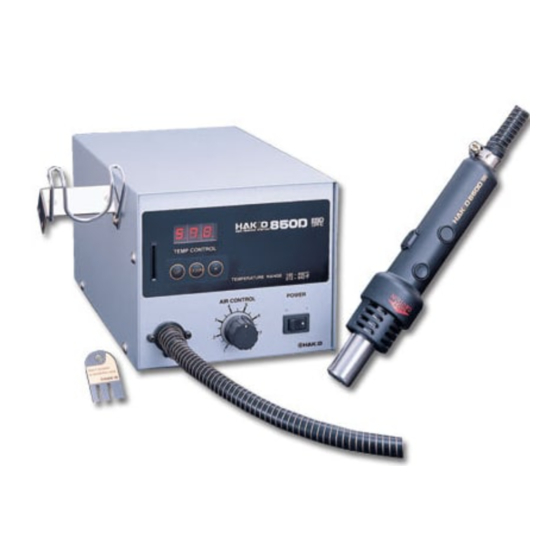
Thank you for purchasing the Hakko 850D SMD Rework
Station. This unit features digital control and display of hot
air temperature.
Please read this manual before operating the Hakko 850D.
Keep this manual readily accessible for reference.
PACKING LIST / SPECIFICATIONS ..................................................... 1
SAFETY INSTRUCTIONS .................................................................... 2
PART NAMES ....................................................................................... 3
OPERATION ......................................................................................... 5
PARAMETERS / INITIAL RESETTING ................................................ 7
USE ...................................................................................................... 8
MAINTENANCE / INSPECTION ........................................................ 10
ERROR MESSAGES ......................................................................... 11
TROUBLESHOOTING ....................................................................... 12
OPTIONAL NOZZLE .......................................................................... 13
PARTS LIST / STATION ...................................................................... 15
WIRING DIAGRAM ............................................................................ 18
SMD Rework Station
G
G
TABLE OF CONTENTS
HANDPIECE ................................................................ 17
Advertisement
Table of Contents

Related Manuals for Hakko Electronics 850D


Summary of Contents for Hakko Electronics 850D
-
Page 1: Table Of Contents
® SMD Rework Station Thank you for purchasing the Hakko 850D SMD Rework Station. This unit features digital control and display of hot air temperature. Please read this manual before operating the Hakko 850D. Keep this manual readily accessible for reference. -
Page 2: Packing List / Specifications
PACKING LIST * This product does not include a nozzle. A large Hakko 850D station ..........1 selection of nozzles is available for the Hakko 850D. Handpiece holder ..........1 Select the nozzle or nozzles suitable for the work Control card ............1 to be performed. -
Page 3: Safety Instructions
G Advise those in the work area that the unit can reach very high temperatures and should be considered potentially dangerous. G Turn the power OFF when no longer using the Hakko 850D or when leaving it unattended. G Before replacing parts or storing the unit, allow the unit to cool and then turn the power OFF. -
Page 4: Part Names
PART NAMES Station Temperature setting section Handpiece holder Handpiece holder mounting screw mounting screw TEMP CONTROL Heater DOWN indicator lamp TEMPERATURE RANGE 100-450°C 212-842°F Power switch AIR CONTROL POWER ® Airflow control knob Jack for optional foot-switch Fuse CAUTION This jack is for the foot- Handpiece holder switch only. -
Page 5: Preparation: Assembly And Electrical Connection
(Figure 2) nozzle as shown in the drawing. (Figure 2) (Figure 3) When installing an optional nozzle to the Hakko 850D, do not remove this inside screw. C. Electrical Connection and Power ON CAUTION This product is ESD-protected. Be sure to use a grounded 1. -
Page 6: Operation
This card is used when entering data for the process control functions. Any Hakko 850D card can be used with any Hakko 850D SMD rework station. Using the control card The control card is used when a value is to be changed or data are to be entered. - Page 7 Setting/Changing the Temperature CAUTION The temperature setting range is 100 – 450°C (212 – 842°F). G Attempt to enter a value outside the setting range will cause the display to begin flashing the HUNDREDS digit again. Reenter a correct value. G Both the display temperature and the temperature setting are the temperature at the sensor.
-
Page 8: Parameters / Initial Resetting
PARAMETERS / INITIAL RESETTING GEntering the Parameters The Hakko 850D has the following three parameters: 1) °C or °F temperature display selection 2) Power save time (select 30 or 60 minutes) 3) Sensor temperature display Once the station enters parameter mode, set the parameters in the order shown below. -
Page 9: Use
G QFP Desoldering 1. Set the temperature and adjust the air flow control knob. TEMP CONTROL Set the temperature (refer to page 6) and DOWN adjust the air flow control knob to desired TEMPERATURE RANGE 100-450°C 212-842°F temperature and the level. AIR CONTROL POWER WARNING... - Page 10 G QFP Soldering 1. Apply the solder paste. Apply the proper quantity of solder paste and install the SMD on the PWB. 2. Preheat the SMD. Preheat the SMD as shown in the photo. 3. Soldering Heat the lead frame evenly. 4.
-
Page 11: Maintenance / Inspection
MAINTENANCE / INSPECTION GBroken Heater or Sensor (1) Open the handpiece. 1. Remove the three screws holding the handpiece together. 2. Move the tube downward. 3. Remove the pipe from the protruding Heater connector portion of the handle. CAUTION Quartz glass and heat insulation are inside the pipe. Be careful not to drop or lose these items. -
Page 12: Error Messages
ERROR MESSAGES When the error detection software in the Hakko 850D detects an error, a message is displayed to alert the operator. See “Troubleshooting” for procedures to correct the error. Sensor Error This error occurs when there is the possibility of a sensor failure (or a failure in the sensor circuit). -
Page 13: Troubleshooting
TROUBLESHOOTING WARNING G Before checking the inside of the Hakko 850D or replacing parts, be sure to disconnect the power plug. Failure to do so may result in electric shock. G The unit does not operate CHECK : Is the fuse blown? -
Page 14: Optional Nozzle
OPTIONAL NOZZLE mm (inch) NOTE The size in Name/Specification indicates the size of IC package. C 0.8 (0.03) C 1.0 (0.04) C 1.0 (0.04) C 0.8 (0.03) D 1.8 (0.07) D 1.8 (0.07) D 2.0 (0.08) D 2.0 (0.08) PLCC A1189B A1191 A1192... - Page 15 A1189B PLCC 34 x 34 A1186B TSOL 18 x 10 A1187B TSOL 18.5 x 8 A1188B PLCC 9 x 9 A1190 Dual Single (1.34 x 1.34) (0.71 x 0.39) (0.73 x 0.31) (0.35 x 0.35) 2.5 x 9.5 (100 Pins) (20 Pins) Pitch (0.09 x 0.37) A:11 (0.43)
-
Page 16: Parts List / Station
PARTS LIST / STATION *Spare or repair parts do not include mounting screws, if they are not listed on the description. Screws must be ordered separately. Item No. Part No. Part Name Description B2732 P.W.B./display B2462 P.W.B./heat control 100-120 V With triac B2463 Radiation sheet B2317... - Page 17 PARTS LIST / HANDPIECE *Spare or repair parts do not include mounting screws, if they are not listed on the description. Screws must be ordered separately. Tapping screw Tapping screw (Fluted point) (M3 x 12) (3) (M2.6 x 6) (3) Tapping screw (M2.6 x 10) (2) Item No.
-
Page 18: Handpiece
WIRING DIAGRAM Pump P.W.B./Display Jack for foot switch Handpiece Terminal board CA sensor CN10 Heater P.W.B./Triac Heater element P.W.B./Heat control Power switch Fuse AC15V Power cord Transformer... - Page 19 HEAD OFFICE 4-5, SHIOKUSA 2-CHOME, NANIWA-KU, OSAKA, 556-0024 JAPAN TEL:+81-6-6561-3225 FAX:+81-6-6561-8466 http://www.hakko.com/ AMERICAN HAKKO PRODUCTS, INC. 28920 N. AVENUE WILLIAMS VALENCIA CA 91355, U.S.A. TEL: (661) 294-0090 FAX: (661) 294-0096 Toll Free (800)88-HAKKO Nov. 2001 4 2 5 5 6 http://www.hakkousa.com/ MA01081JU011107...
Need help?
Do you have a question about the 850D and is the answer not in the manual?
Questions and answers