Table of Contents
Advertisement
Quick Links
®
Instruction Manual
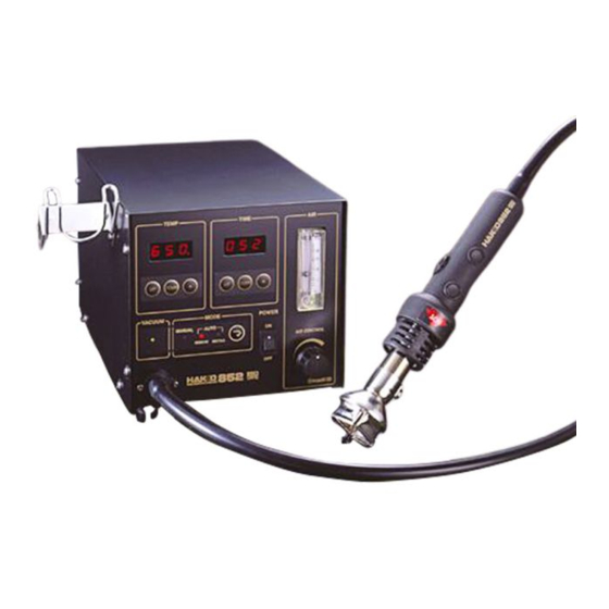
Thank you for purchasing the Hakko 852 SMD Rework
Station. This unit features:
● Digital control and display of time and temperature
● Display of air-flow rate
● Manual and automatic modes
● Built-in vacuum pickup
Please read this manual before operating the Hakko 852.
Keep this manual readily accessible for reference.
10. ERROR MESSAGES .............................................. 16
11. TROUBLESHOOTING ............................................ 16
12. OPTIONAL PARTS ................................................. 17
13. PARTS LIST / STATION ......................................... 19
14. PARTS LIST / HANDPIECE .................................... 21
15. WIRING DIAGRAM ................................................. 22
SMD Rrework Station
with Vacuum Pickup
TABLE OF CONTENTS
1. PACKING LIST .......................................................... 1
2. SPECIFICATIONS ..................................................... 1
3. SAFETY INSTRUCTIONS ......................................... 2
4. PART NAMES ........................................................... 3
7. OPERATION ............................................................. 8
8. PARAMETERS / INITIAL RESETTING ................... 14
9. MAINTENANCE / INSPECTION ............................. 15
●
●
Advertisement
Table of Contents

Related Manuals for Hakko Electronics 852


Summary of Contents for Hakko Electronics 852
-
Page 1: Table Of Contents
SMD Rrework Station with Vacuum Pickup Instruction Manual ● Thank you for purchasing the Hakko 852 SMD Rework Station. This unit features: ● Digital control and display of time and temperature ● Display of air-flow rate ● Manual and automatic modes ●... -
Page 2: Packing List
1. PACKING LIST Check the contents of the Hakko 852 package and confirm that all the items listed below are included. Hakko 852 station ..........1 * This product does not include a nozzle. A large selection of nozzles is available for the Hakko Power cord ............ -
Page 3: Safety Instructions
● Advise those in the work area that the unit can reach very high temperatures and should be considered potentially dangerous. ● Turn the power OFF when no longer using the Hakko 852 or when leaving it unattended. ● Before replacing parts or storing the unit, allow the unit to cool and then turn the power OFF. -
Page 4: Part Names
4. PART NAMES ㈰Temperature setting section Station ㈪Timer setting section ㈫Airflow setting section ㈬Airflow meter Handpiece holder TEMP TIME mounting screw Handpiece holder mounting screw ㈭Power switch Heater indicator lamp VACUUM MODE POWER ㈮Airflow control knob AIR CONTROL ㉀Vacuum indicator ㈯Mode setting section Jack for optional foot-switch... - Page 5 Station ① Temperature setting section ..Use this section for displaying and setting the temperature. The tem- perature range is 100 to 450°C. (212 to 842°F.). The temperature is (temperature setting function) factory-set to 300°C. (572°F.)..Use these buttons to increase and decrease the tempera- UP DOWN ture.
-
Page 6: Preparation: Assembly And Electrical Connection
5. PREPARATION: ASSEMBLY AND ELECTRICAL CONNECTION Preparation: Assembly and Electrical Connectio A. Station Assembly ● Attach the handpiece holder. Remove the handpiece holder mounting screw from the side of the station. Attach the handpiece holder to the station. (Fig- ure 1) (The handpiece holder can be installed on either the left or right side.) (Figure 1) - Page 7 ● Using vacuum function inop- erative nozzle (see page 18.) Attach the nozzle. a. Retract the vacuum pipe to the short- est length using the vacuum pipe con- trol knob. (Figure 5) b. Loosen the nozzle mounting screw. Attach the nozzle. (Figure 4) c.
-
Page 8: Preparation: Assembly And Electrical Connection
AUTO Select the desired mode using the mode REMOVE INSTALL selection button. The Hakko 852 provides the following (Figure 9 ) three modes: ● Manual Mode (See page 8.) In this mode, air-blow start and vacuum pump operation are handled entirely by manual operation. Use this mode... -
Page 9: Operation
7. OPERATION Operation in Manual Mode TEMP TIME ● Selecting Manual Mode When checking the Press the mode selection button and set temperature setting the mode to MANUAL. Press the button for less VACUUM MODE POWER than one second. To change The timer does not operate. - Page 10 7. OPERATION Auto/Remove Mode TEMP TIME ● Selecting Remove Mode Press the mode selection button and set the mode to REMOVE. This mode has VACUUM MODE POWER the following sequence: ① Start/hot air blow (manual) ② Vacuum ON five seconds before the timer runs out (automatic) To check the temperature set- To c h a n g e t h e a i r...
- Page 11 Auto/Install Mode TEMP TIME ● Selecting Install Mode Press the mode selection button and set the mode to INSTALL. This mode has the VACUUM MODE POWER following sequence: ① Vacuum ON (manual) ② Start/hot air blow (manual) ③ Vacuum OFF after five seconds To check the temperature set- To c h a n g e t h e a i r (automatic)
- Page 12 7. OPERATION Setting/Changing the Temperature CAUTION TEMP TIME The temperature setting range is 100 – 450°C. (212 – 842°F). ● Attempt to enter a value outside the setting range Temperature will cause the display to begin flashing the HUN- setting section VACUUM MODE POWER...
- Page 13 Setting/Changing the Time Timer setting section TEMP TIME CAUTION The timer setting range is 15 – 999 seconds. ● Attempt to enter a value outside the setting range will cause the display to begin flashing the HUN- DREDS digit again. Reenter a correct value. VACUUM MODE POWER...
- Page 14 7. OPERATION Airflow Adjustment Adjust the flow rate of the hot air while TEMP TIME watching the airflow meter. The adjust- ment range is 7l/min to 20l/min. VACUUM MODE POWER Read from CAUTION the center AIR CONTROL of the ball. Do not apply excessive force when turning the airflow control knob.
-
Page 15: Parameters / Initial Resetting
8. PARAMETERS / INITIAL RESETTING ● Entering the Parameters The Hakko 852 has the following three parameters: 1) °C or °F temperature display selection 2) Power save time (select 30 or 60 minutes) 3) Sensor temperature display Once the station enters parameter mode, set the parameters in the order shown below. -
Page 16: Maintenance / Inspection
9. MAINTENANCE / INSPECTION ● Broken Heater or Sensor ① Open the handpiece. 1. Retract the vacuum pipe to its shortest length. 2. Remove the three screws holding the handpiece together. 3. Move the tube downward. Heater connector 4. Remove the pipe from the protruding portion of the handle. -
Page 17: Error Messages
flashes to indicate the possibility of a heater failure. 11. TROUBLESHOOTING WARNING ● Before checking the inside of the Hakko 852 or replacing parts, be sure to disconnect the power plug. Failure to do so may result in electric shock. ● The unit does not operate... -
Page 18: Optional Parts
12. OPTIONAL PARTS mm (inch) �Nozzles PLCC C 0.8 (0.03) C 1.0 (0.04) C 0.8 (0.03) NOTE D 1.8 (0.07) D 2.0 (0.08) D 2.0 (0.08) The size in Name/ Air flow A1125B~A1129B A1191 A1192 A1131~A1141B Specification indicates A1180B~A1189B the size of IC package. A1203B~A1265B �VACUUM FUNCTION OPERATIVE NOZZLES. - Page 19 CAUTION Be sure not to use No. A1124 Single ø2.5 (0.09) and No. A1142 Bent Single 1.5 x 3 (0.06 x 0.12) nozzle with the Hakko 852. These nozzles do not have space to blow hot air, using them with the 852 may result in danger.
-
Page 20: Parts List / Station
13. PARTS LIST / STATION *Spare or repair parts do not include mounting screws, if they are not listed on the description. Screws must be ordered separately. Item No. Part No. Part Name Description B2461 P.W.B./display B2462 P.W.B./heat control 100-120 V With triac B2482 P.W.B./heat control 220-240 V With triac... -
Page 21: Parts List / Handpiece
14. PARTS LIST / HANDPIECE *Spare or repair parts do not include mounting screws, if they are not listed on the description. Screws must be ordered separately. Tapping screw Tapping screw (Fluted point) (M3 × 12) (3) (M2.6 × 6) (3) Tapping screw (M2.6 ×... -
Page 22: Wiring Diagram
15. WIRING DIAGRAM Hot air pump Jack for foot-switch P.W.B./Display Handpiece Terminal board CA sensor Heater P.W.B./Triac P.W.B./Heat control Heater element Power switch AC15V Power Vacuum pump Transformer receptacle... - Page 23 HEAD OFFICE TEL:+81-6-6561-3225 FAX:+81-6-6561-8466 http://www.hakko.com E-mail:sales@hakko.com OVERSEAS AFFILIATES U.S.A.: AMERICAN HAKKO PRODUCTS, INC. TEL: (661) 294-0090 FAX: (661) 294-0096 Toll Free (800)88-HAKKO 4 2 5 5 6 http://www.hakkousa.com HONG KONG: HAKKO DEVELOPMENT CO., LTD. TEL: 2811-5588 FAX: 2590-0217 http://www.hakko.com.hk E-mail:info@hakko.com.hk SINGAPORE: HAKKO PRODUCTS PTE., LTD.
Need help?
Do you have a question about the 852 and is the answer not in the manual?
Questions and answers