
Related Manuals for Vaisala HMP60


Summary of Contents for Vaisala HMP60
- Page 1 USER'S GUIDE Vaisala Humidity and Temperature Probes HMP60, HMP110 and HMP110T M211060EN-C...
- Page 2 The contents are subject to change without prior notice. Please observe that this manual does not create any legally binding obligations for Vaisala towards the customer or end user. All legally binding commitments and agreements are included exclusively in the applicable supply contract or Conditions of...
-
Page 3: Table Of Contents
Trademarks ................9 License Agreement ..............9 Warranty..................9 CHAPTER 2 PRODUCT OVERVIEW................11 Introduction to HMP60, HMP110, and HMP110T ....11 Basic Features and Options..........12 Filter Options ............... 13 Installation Accessories (Optional) ........14 Probe Mounting Clamp ............14 Probe Mounting Flange............ - Page 4 One-Point Adjustment of RH Measurement (HMP110) ..49 Two-Point Adjustment of RH Measurement (HMP110) ..50 One-Point Adjustment of T Measurement (HMP110 and HMP110T) ................52 Repair Maintenance..............54 Changing the INTERCAP® Sensor (HMP60) .....54 Changing the HUMICAP® 180R Sensor (HMP110) ...55 2 ___________________________________________________________________ M211060EN-C...
- Page 5 Solving Typical Problems ............. 57 Technical Support ..............58 Product Returns ..............58 CHAPTER 7 TECHNICAL DATA ..................59 Specifications ................. 59 Performance (HMP60) ............59 Relative Humidity ............59 Temperature..............59 Dewpoint ................ 59 Performance (HMP110) ............60 Relative Humidity ............60 Temperature..............
- Page 6 List of Tables Table 1 Manual Revisions ...............6 Table 2 Related Manuals.................6 Table 3 Quantities Measured by the HMP60 and HMP110 ....12 Table 4 Quantities Measured by the HMP110T ........12 Table 5 Filter Properties ................13 Table 6 Pinout of the Probe Connector ..........22 Table 7 Default Serial Communication Settings........26...
-
Page 7: Chapter 1 General Information
This chapter provides general notes for the manual and the products. About This Manual This manual provides information for installing, operating, and maintaining Vaisala Humidity and Temperature Probes HMP60, HMP110 and HMP110T. Contents of This Manual This manual consists of the following chapters: - Chapter 1, General Information, provides general notes for the manual and the products. -
Page 8: Version Information
Technical specification updated. Related Manuals Table 2 Related Manuals Manual Code Manual Name M211059EN HMP60, HMP110 and HMP110T Quick Guide M211106EN Loop Power Converter Quick Reference Guide M211080EN Mounting Flange for Humidity Probes Quick Reference Guide Documentation Conventions Throughout the manual, important safety considerations are highlighted... -
Page 9: Safety
ESD Protection Electrostatic Discharge (ESD) can cause immediate or latent damage to electronic circuits. Vaisala products are adequately protected against ESD for their intended use. It is possible to damage the product, however, by delivering electrostatic discharges when touching, removing, or inserting any objects inside the equipment housing. -
Page 10: Recycling
EN 55022 Class B: Information technology equipment - Radio disturbance characteristics - Limits and methods of measurement. Patent Notice The HMP60 and HMP110 are protected by the following patents and patent applications and their corresponding national rights: Finnish patent 98861, French patent 6650303, German patent 69418174, Japanese patent 3585973, UK patent 0665303, U.S. -
Page 11: Trademarks
United States and/or other countries. License Agreement All rights to any software are held by Vaisala or third parties. The customer is allowed to use the software only to the extent that is provided by the applicable supply contract or Software License Agreement. - Page 12 User's Guide ______________________________________________________________________ This page intentionally left blank. 10 __________________________________________________________________ M211060EN-C...
-
Page 13: Chapter 2 Product Overview
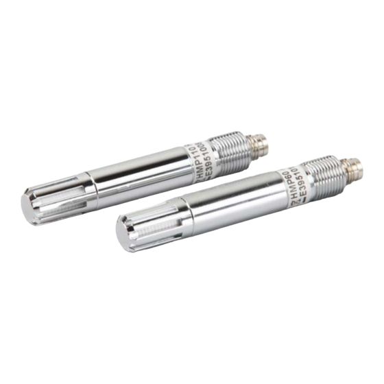
HMP110 uses the Vaisala HUMICAP® 180R sensor for increased accuracy. The HMP110 requires calibration after sensor replacement. This can be done on the serial line using the optional Vaisala USB cable. 0912-101 Figure 1... -
Page 14: Basic Features And Options
ºF Basic Features and Options - HMP60 and HMP110 analog output mode: two analog output channels, selectable from 0 ... 1 V / 0 ... 2.5 V / 0 ... 5 V / 1 ... 5 V - HMP110T: analog output mode: single analog output channel (CH1), selectable from 0 ... -
Page 15: Filter Options
Chapter 2 __________________________________________________________ Product Overview Filter Options The available filters for HMP60, HMP110 and HMP110T are shown in Figure 2 below. For order codes, see section Options and Accessories on page 62. 1001-008 Figure 2 Filter Options Table 5 Filter Properties No. -
Page 16: Installation Accessories (Optional)
The flange is a general purpose mounting accessory for Ø 12mm probes, and comes with a sealing plug for coaxial cables that is not needed when the flange is used with HMP60, HMP110 and HMP110T. 0911-109 Figure 4... -
Page 17: Duct Installation Kit
Chapter 2 __________________________________________________________ Product Overview Duct Installation Kit The duct installation kit includes a plastic pipe with a flange (Vaisala order code: 215619). To install the probe with the duct installation kit, drill a hole to the duct wall, assemble the probe to the duct installation kit, slide the probe head through the hole, and attach the flange to the duct wall with four screws. -
Page 18: Loop Power Converter
User's Guide ______________________________________________________________________ Loop Power Converter The loop power converter is an open frame module that converts one 0 ... 2.5 VDC voltage output to a 4 ... 20 mA current output. To use the loop power converter module, the probe: - must be in the analog output mode - the desired quantity must be on channel 1 - channel 1 must be scaled to 0 ... -
Page 19: Cables
M8 series cables can be used. 0910-135 Figure 7 Cable with Threaded Connector The USB Serial Interface Cable uses a snap-on connector. The USB cable is intended for maintenance purposes only, not for permanent installation. 0809-002 Figure 8 USB Serial Interface Cable VAISALA _______________________________________________________________________ 17... - Page 20 User's Guide ______________________________________________________________________ This page intentionally left blank. 18 __________________________________________________________________ M211060EN-C...
-
Page 21: Dimensions
Chapter 3 _______________________________________________________________ Installation CHAPTER 3 INSTALLATION This chapter provides you with information that is intended to help you install the product. Dimensions 0912-103 Figure 9 HMP60, HMP110, and HMP110T Dimensions 0912-102 Figure 10 Installation with Plastic M12 Nuts, Dimensions VAISALA _______________________________________________________________________ 19... -
Page 22: Mounting The Probe
User's Guide ______________________________________________________________________ Mounting the Probe HMP60, HMP110 and HMP110T are designed to be mounted from the M12 thread on the probe body or from the smooth part of the probe body. For a convenient installation, use the optional installation accessories: - Use the plastic mounting nuts to hold the probe in a through-wall installation. -
Page 23: Drilling Instructions For Duct Installation Kit
Drill holes for the duct installation kit mounting screws around the hole in a square arrangement, 42 mm apart from each other. Use a 3.2-mm drill bit to drill the holes for the mounting screws (four ST4.2×16-C-Z DIN 7981 screws). VAISALA _______________________________________________________________________ 21... -
Page 24: Wiring
For a secure connection to the probe, connect to the 4-pin M8 connector using a threaded connector. Connect the shield if using a shielded cable. In the shielded cables supplied by Vaisala, the threaded connector connects the shield to the probe housing. 0912-104... -
Page 25: Wiring With The Loop Power Converter
Chapter 3 _______________________________________________________________ Installation Wiring with the Loop Power Converter To use the loop power converter module with HMP60, HMP110, or HMP110T, make sure that: - The probe is in the analog output mode - The desired quantity must be on channel 1 - Channel 1 is scaled to 0 ... -
Page 26: Power Supply Requirements
User's Guide ______________________________________________________________________ Power Supply Requirements The operating voltage for the HMP60, HMP110 and HMP110T probes must be in the following range: - 5 ... 28 VDC when using the 0 ... 1 V, 0 ... 2.5 V or RS-485 output - 8 ... -
Page 27: Chapter 4 Operation
20. For temporary use of the serial interface (for example, calibration), you can use the optional USB cable (Vaisala order code: 219690). Before you can use the USB cable, you must install the provided USB driver on your PC, see Installing the Driver for the USB Cable on page 26. -
Page 28: Table 7 Default Serial Communication Settings
User's Guide ______________________________________________________________________ NOTE The Vaisala USB cable is not designed for permanent installation. When using the USB cable, no separate power unit is needed. The probe is powered through the USB port. For permanent interfacing to a host system, use a shielded cable with a threaded connector. -
Page 29: Installing The Driver For The Usb Cable
COM port. There is no reason to uninstall the driver for normal use. However, if you wish to remove the driver files and all Vaisala USB cable devices, you can do so by uninstalling the entry for Vaisala USB Instrument Driver from the Add or Remove Programs (Programs and Features in Windows Vista) in the Windows Control Panel. -
Page 30: Terminal Application Settings For Probes In Rs-485 Mode
User's Guide ______________________________________________________________________ Terminal Application Settings for Probes in RS-485 Mode The steps below describe how to connect to the HMP60, HMP110 and HMP110T using the PuTTY terminal application for Windows (available for download at www.vaisala.com) and the USB serial interface. The instructions assume that your probe has been ordered with the RS-485 output. -
Page 31: Figure 16 Putty Terminal Application
Chapter 4 ________________________________________________________________ Operation 0810-070 Figure 16 PuTTY Terminal Application VAISALA _______________________________________________________________________ 29... -
Page 32: Terminal Application Settings For Probes In Analog Mode
Select the Serial settings category, and check that the correct COM port is selected in the Serial line to connect to field. You can check which port the USB cable is using with the Vaisala USB Instrument Finder program that has been installed in the Windows Start menu. -
Page 33: List Of Serial Commands
View or set serial line answer minimum delay SEND [0 ... 99] Output the reading once SNUM View the serial number of the probe UNIT Select metric or non-metric output units VERS View software version of the probe VAISALA _______________________________________________________________________ 31... -
Page 34: Device Information And Status
Set the serial interface mode [STOP/RUN/POLL] Device Information and Status View Device Information The ? command outputs a listing of device information. ?<cr> Example: HMP60 / 1.00.0 Serial number : E3950006 Batch number : E3950006 Sensor number : A0000000 Sensor model... -
Page 35: View Calibration Information
This command is useful if you need to order a new probe with the same options. CODE<cr> Example: code Order code : A12A01B0 View Serial Number Use the SNUM command to view the serial number of the probe. SNUM<cr> Example: snum Serial number : E3950006 VAISALA _______________________________________________________________________ 33... -
Page 36: View Software Version
Use the R command to start the continuous outputting of measurement values as an ASCII text string to the serial line. For HMP60 and HMP110, the output always includes readings for temperature, RH and Td. For HMP110T, the output includes only temperature. -
Page 37: Output The Measurement Message Once
(300, 600, 1200, 2400, 4800, 9600, 19200, 38400, 57600) parity (n = none, e = even, o = odd) data bits (7 or 8) stop bits (1 or 2) Example (shows default settings): seri Baud P D S 19200 N 8 1 VAISALA _______________________________________________________________________ 35... -
Page 38: Set Serial Interface Mode
User's Guide ______________________________________________________________________ Set Serial Interface Mode SMODE [xxx]<cr> where STOP, RUN, or POLL In STOP mode: outputting only when command is issued, any command can be used. In RUN mode: outputting automatically, only command S can be used. In POLL mode: outputting only when command is issued, any command can be used after the line has been opened using the OPEN command. -
Page 39: Set Output Interval
1.0 = No filtering, latest measurement is output without averaging 0.5 = Average of last two measurements 0.1 = Average of approximately 16 measurements Example (default setting, no filtering): filt Filter 1.000 Example (set filtering to 0.5): filt 0.5 Filter 0.500 VAISALA _______________________________________________________________________ 37... -
Page 40: Set Probe Address
User's Guide ______________________________________________________________________ Set Probe Address Use the ADDR command to view or set the probe address. To operate in the POLL mode, the probe must have an address. If multiple probes share the same serial line, each probe must have a different address. For a description of the serial interface modes, see section Set Serial Line Settings on page 35. -
Page 41: Set Measurement Units
UNIT [M/N]<cr> M is for metric units, N is for non-metric units. Quantity Metric Unit Non-Metric Unit ºC ºF ºC ºF Examples: unit Units : Metric unit n Units : Non metric VAISALA _______________________________________________________________________ 39... -
Page 42: Calibration Commands
User's Guide ______________________________________________________________________ Calibration Commands Calibrate Humidity Measurement Use the CRH command to perform a one-point or two-point correction to the capacitance measurement of the probe. This command changes the offset and/or gain of the humidity measurement, depending on the calibration and reference: - one-point calibration with a single <... -
Page 43: Clear Adjustment Of Rh Measurement
30 ºC. To update the measured value while the command is running, press enter without inputting a value. Example: two-point calibration 22.03 Ref1 ? 22 Press any key when ready ... 55.12 Ref2 ? 55 VAISALA _______________________________________________________________________ 41... -
Page 44: Clear Adjustment Of T Measurement
User's Guide ______________________________________________________________________ Clear Adjustment of T Measurement Use the CTCLR command to clear the adjustment of temperature measurement that has been done using the CT command. CTCLR<cr> Example: ctclr View User Adjustment Parameters Use the L command to view the current user adjustment parameters. This command is useful for checking the currently applied customer calibration. -
Page 45: Other Commands
Ch2 output 0 ... 1 V Example (set channel 1 to 0 ... 1 V and channel 2 to 0 ... 5 V): amode 0 2 Ch1 output 0 ... 1 V Ch2 output 0 ... 5 V VAISALA _______________________________________________________________________ 43... -
Page 46: Extend Analog Output Range
User's Guide ______________________________________________________________________ Extend Analog Output Range Use the AOVER command to allow the analog output channels to exceed their specified range by 10%. The scaling of the quantity remains as before; the extra range is used for additional measurement range in the wet end. -
Page 47: Connect To The Probe In Poll Mode
RESET<cr> Example (probe set to serial mode STOP, will output probe model and software version at reset): reset HMP60 / 1.00.0 Example (probe set to serial mode RUN, will start to output measurement messages at reset): reset T= 23.6 'C RH= 20.2 %RH Td= -0.5 'C T= 23.6 'C RH= 20.2 %RH Td= -0.5 'C... -
Page 48: Restore Factory Settings
User's Guide ______________________________________________________________________ Restore Factory Settings Use the FRESTORE command to restore the factory settings to the probe. All user settings, including the user-performed calibration corrections, will be lost. The probe will revert back to the factory calibrated settings. FRESTORE<cr> Example: frestore Factory settings restored... -
Page 49: Chapter 5 Maintenance
This chapter provides information that is needed in basic maintenance of the product. Periodic Maintenance The humidity measurement accuracy of the HMP60 and HMP110 should be calibrated yearly. When calibration indicates that accuracy is not within specification: - HMP60: change the INTERCAP® Sensor. -
Page 50: Changing The Filter
To calibrate your probe, you need a known stable humidity or temperature reference, and a way to read the output of the probe (analog or serial). As a humidity reference you can use, for example, the Vaisala Humidity Calibrator HMK15. -
Page 51: Adjustment Procedure (Hmp110)
Measurement (HMP110) To perform a one-point adjustment to the capacitance measurement of the HMP110 you need: - The Vaisala USB cable (Vaisala order code: 219690) - PC with a terminal application. - One humidity reference. One-point calibration with a single <... -
Page 52: Two-Point Adjustment Of Rh Measurement (Hmp110)
To perform a two-point adjustment to the capacitance measurement of the HMP110 you need: - The Vaisala USB cable (Vaisala order code: 219690) - PC with a terminal application. - Two humidity references. The first point requires a < 50 %RH humidity reference, the second point must be >... - Page 53 Check with the L command that the user adjustment parameters have changed. If you wish to remove the effects of RH calibration (returning the RH measurement of the HMP110 to the factory calibrated state), see section Clear Adjustment of RH Measurement on page 41. VAISALA _______________________________________________________________________ 51...
-
Page 54: One-Point Adjustment Of T Measurement (Hmp110 And Hmp110T)
(HMP110 and HMP110T) To perform a one-point adjustment to the temperature measurement of the HMP110 or HMP110T you need: - The Vaisala USB cable (Vaisala order code: 219690) - PC with a terminal application. - One known and stable temperature reference. - Page 55 Check with the L command that the user adjustment parameters have changed. If you wish to remove the effects of T calibration (returning the T measurement of the probe to the factory calibrated state), see section Clear Adjustment of T Measurement on page 42. VAISALA _______________________________________________________________________ 53...
-
Page 56: Repair Maintenance
(HMP60) This procedure restores the humidity measurement accuracy of the HMP60. No adjustment after the sensor change is needed. To perform this procedure, you need a new INTERCAP® sensor. It is also recommended that you replace the filter with a new one. For order codes, see section Options and Accessories on page 62. -
Page 57: Changing The Humicap® 180R Sensor (Hmp110)
54. Handle the new sensor by the plastic frame. DO NOT TOUCH THE SENSOR PLATE. Perform a two-point adjustment of the RH measurement as instructed in section Two-Point Adjustment of RH Measurement (HMP110) on page 50. Attach a new filter on the probe. VAISALA _______________________________________________________________________ 55... - Page 58 User's Guide ______________________________________________________________________ This page intentionally left blank. 56 __________________________________________________________________ M211060EN-C...
-
Page 59: Chapter 6 Troubleshooting
Solving Typical Problems You can check the error message via the serial interface by using the ERRS command. If you are unable to remove the errors, contact Vaisala technical support. See section Technical Support on page 58. Table 10... -
Page 60: Technical Support
2. If the error is still active, contact Vaisala - Parameter flash check sum technical support. error Technical Support For technical questions, contact the Vaisala technical support by e-mail at helpdesk@vaisala.com. For contact information of Vaisala Service Centers, see www.vaisala.com/services/servicecenters.html. Product Returns If the product must be returned for service, see www.vaisala.com/services/return.html. -
Page 61: Chapter 7 Technical Data
Chapter 7 ____________________________________________________________ Technical Data CHAPTER 7 TECHNICAL DATA This chapter provides the technical data of the product. Specifications Performance (HMP60) Relative Humidity Measurement range 0 ... 100 %RH Typical accuracy temperature range +0 ... +40 °C 0 ... 90 %RH ±3 %RH... -
Page 62: Performance (Hmp110)
0 ... 90 %RH ±3.0 %RH 90 ... 100 %RH ±4.0 %RH Factory calibration uncertainty (+20 °C) ±1.5 %RH Humidity sensor Vaisala HUMICAP® 180R Temperature Measurement range -40 ... +80 °C Accuracy over temperature range 0 ... +40 °C ±0.2 °C -40 ... -
Page 63: Operating Environment
Chrome coated ABS plastic cable Polyurethane Housing classification IP65 Body thread M12x1 / 10 mm Cable connector 4-pin M8 (IEC 60947-5-2) Cable lengths 0.3 and 3 m Weight probe 17 g probe with 0.3 m cable 28 g VAISALA _______________________________________________________________________ 61... -
Page 64: Options And Accessories
User's Guide ______________________________________________________________________ Options and Accessories Table 11 HMP60 Options and Accessories Description Item Code Vaisala INTERCAP® sensor 15778HM Vaisala INTERCAP® sensor, 10 pcs INTERCAPSET-10PCS Probe mounting flange 226061 Probe mounting clamps, 10 pcs 226067 Sensor protection Plastic grid filter... -
Page 65: Table 13 Hmp110T Options And Accessories
215619 Shielded cable, 0.3 m HMP50Z032SP Shielded cable, 3 m HMP50Z300SP Shielded cable (+80 ºC), 1.5 m 225777SP Shielded cable (+80 ºC), 3 m 225229SP FEP cable (+180 ºC), 3 m 226902SP USB serial interface cable 219690 VAISALA _______________________________________________________________________ 63... - Page 66 *M211060EN*...
Need help?
Do you have a question about the HMP60 and is the answer not in the manual?
Questions and answers