
Vaisala HMP110 series Manuals
Manuals and User Guides for Vaisala HMP110 series. We have 5 Vaisala HMP110 series manuals available for free PDF download: User Manual, Manual
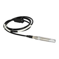
Vaisala HMP110 series User Manual (98 pages)
Humidity and Temperature Probes
Brand: Vaisala
|
Category: Measuring Instruments
|
Size: 2 MB
Table of Contents
Advertisement

Vaisala HMP110 series User Manual (79 pages)
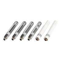
Humidity and Temperature Probes
Brand: Vaisala
|
Category: Accessories
|
Size: 2 MB
Table of Contents
Advertisement

Vaisala HMP110 series User Manual (66 pages)
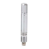
Humidity and Temperature Probes
Brand: Vaisala
|
Category: Test Equipment
|
Size: 0 MB
Table of Contents
Vaisala HMP110 series Manual (4 pages)
HMP60 Series, HMP110 Series, Humidity and Temperature Probes
Brand: Vaisala
|
Category: Measuring Instruments
|
Size: 1 MB