Table of Contents
Advertisement
Quick Links
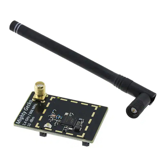
UG178: EFR32MG 2400/868 MHz 13 dBm
Dual Band Radio Board
The SLWRB4150A Radio Board for the Wireless Starter Kit Main-
board is an excellent starting point to get familiar with the
EFR32™ Mighty Gecko Wireless System-on-Chip.
The Wireless Starter Kit Mainboard contains sensors and peripherals demonstrating
some of the Mighty Gecko's many capabilities. These together provide all necessary
tools for developing a Silicon Labs wireless application.
The WSTK Mainboard is included with all Silicon Labs Wireless Starter Kits. It is not in-
cluded when purchasing a single radio board.
silabs.com | Smart. Connected. Energy-friendly.
RADIO BOARD FEATURES
• EFR32 Mighty Gecko Wireless SoC with
256 kB Flash and 32 kB RAM.
(EFR32MG1P233F256GM48)
• Inverted-F PCB antenna (2.4 GHz band)
• SMA connector (868 MHz band)
WSTK MAINBOARD FEATURES
• Ethernet and USB connectivity
• Advanced Energy Monitor
• Packet Trace Interface support
• SEGGER J-Link on-board debugger
• Debug Multiplexer supporting external
hardware as well as radio board
• Silicon Labs' Si7021 Relative Humidity and
Temperature sensor
• Ultra low power 128x128 pixel Memory
LCD
• User LEDs / Pushbuttons
• 20-pin 2.54 mm header for expansion
boards
• Breakout pads for direct access to all radio
I/O pins
• Power sources includes USB, CR2032
coin cell and AA batteries.
SOFTWARE SUPPORT
• Simplicity Studio™
• Energy Profiler
• Network Analyzer
Rev. 1.00
Advertisement
Table of Contents

Related Manuals for Silicon Laboratories SLWRB4150A


Summary of Contents for Silicon Laboratories SLWRB4150A
- Page 1 UG178: EFR32MG 2400/868 MHz 13 dBm Dual Band Radio Board The SLWRB4150A Radio Board for the Wireless Starter Kit Main- RADIO BOARD FEATURES board is an excellent starting point to get familiar with the EFR32™ Mighty Gecko Wireless System-on-Chip. • EFR32 Mighty Gecko Wireless SoC with 256 kB Flash and 32 kB RAM.
-
Page 2: Introduction
1. Introduction The SLWRB4150A Radio Board is a single EFR32MG 2400/868 MHz 13 dBm radio board for the Wireless Starter Kit Mainboard. A radio board and a mainboard used together makes a complete development platform for Silicon Labs EFR32 Mighty Gecko Wireless System-on-Chips. -
Page 3: Kit Hardware Overview
ARM Coresight 19-pin trace/debug header Battery or Ultra-low power 128x128 USB power pixel memory LCD, Serial-port, packet trace and Advanced buttons and LEDs Energy Monitoring header Figure 2.1. SLWRB4150A with Wireless STK Mainboard silabs.com | Smart. Connected. Energy-friendly. Rev. 1.00 | 2... -
Page 4: Block Diagram
UG178: EFR32MG 2400/868 MHz 13 dBm Dual Band Radio Board Block Diagram 3. Block Diagram A system overview of the EFR32MG 2400/868 MHz 13 dBm Dual Band Radio Board used together with an Wireless STK Mainboard is shown in the figure below. Board USB Mini-B Controller... -
Page 5: Connectors
UG178: EFR32MG 2400/868 MHz 13 dBm Dual Band Radio Board Connectors 4. Connectors This chapter gives you an overview of the Wireless Starter Kit Mainboard connectivity. The placement of the connectors can be seen in the figure below. In/Out Debug Simplicity Header Connector... -
Page 6: Expansion Header
UG178: EFR32MG 2400/868 MHz 13 dBm Dual Band Radio Board Connectors 4.2 Expansion Header On the right hand side of the board an angled 20-pin expansion header is provided to allow connection of peripherals or plugin boards. The connector contains a number of I/O pins that can be used with most of the EFR32 Mighty Gecko's features. Additionally, the VMCU, 3V3 and 5V power rails are also exported. -
Page 7: Expansion Header Pin-Out
UG178: EFR32MG 2400/868 MHz 13 dBm Dual Band Radio Board Connectors 4.2.1 Expansion Header Pin-out The pin-routing on the EFR32 is very flexible, so most peripherals can be routed to any pin. However, many pins are shared between the Expansion Header and other functions on the Wireless STK Mainboard. Table 4.1 Expansion Header Pinout on page 6 includes an overview of the mainboard features that share pins with the Expansion Header. -
Page 8: Debug Connector
UG178: EFR32MG 2400/868 MHz 13 dBm Dual Band Radio Board Connectors 4.3 Debug Connector The Debug Connector serves multiple purposes based on the "debug mode" setting which can be configured in Simplicity Studio. When mode is set to "Debug IN", this connector allows an external debug emulator to be used with the radio board EFR32. When set to "De- bug OUT", this connector allows the kit to be used as a debugger towards an external target. -
Page 9: Simplicity Connector
UG178: EFR32MG 2400/868 MHz 13 dBm Dual Band Radio Board Connectors 4.4 Simplicity Connector The Simplicity Connector featured on the Wireless Starter Kit Mainboard enables advanced debugging features such as the AEM, the Virtual COM port and the Packet Trace Interface to be used towards an external target. The pinout is illustrated in the figure below. VMCU Virtual COM TX / MOSI Virtual COM RX / MISO... -
Page 10: Power Supply And Reset
UG178: EFR32MG 2400/868 MHz 13 dBm Dual Band Radio Board Power Supply and Reset 5. Power Supply and Reset 5.1 Radio Board Power Selection The EFR32 on a Wireless Starter Kit can be powered by one of these sources: • the debug USB cable; •... -
Page 11: Board Controller Power
UG178: EFR32MG 2400/868 MHz 13 dBm Dual Band Radio Board Power Supply and Reset 5.2 Board Controller Power The board controller is responsible for important features such as the debugger and the Advanced Energy Monitor, and is powered exclusively through the USB port in the top left corner of the board. This part of the kit resides on a separate power domain, so a differ- ent power source can be selected for the target device while retaining debugging functionality. -
Page 12: Peripherals
UG178: EFR32MG 2400/868 MHz 13 dBm Dual Band Radio Board Peripherals 6. Peripherals The starter kit has a set of peripherals that showcase some of the features of the EFR32. Be aware that most EFR32 I/O routed to peripherals are also routed to the breakout pads. This must be taken into consideration when using the breakout pads for your application. -
Page 13: Memory Lcd-Tft Display
UG178: EFR32MG 2400/868 MHz 13 dBm Dual Band Radio Board Peripherals 6.2 Memory LCD-TFT Display A 1.28-inch SHARP Memory LCD-TFT is available on the kit to enable interactive applications to be developed. The display has a high resolution of 128 by 128 pixels, and consumes very little power. It is a reflective monochrome display, so each pixel can only be light or dark, and no backlight is needed in normal daylight conditions. -
Page 14: Serial Flash
UG178: EFR32MG 2400/868 MHz 13 dBm Dual Band Radio Board Peripherals 6.3 Serial Flash The BRD4150A radio board is equipped with an 8 Mbit Macronix MX25R SPI flash that is connected directly to the EFR32 Mighty Gecko. Figure 6.3 Radio Board Serial Flash on page 13 shows how the serial flash is connected to the EFR32. -
Page 15: Si7021 Relative Humidity And Temperature Sensor
UG178: EFR32MG 2400/868 MHz 13 dBm Dual Band Radio Board Peripherals 6.4 Si7021 Relative Humidity and Temperature Sensor The Si7021 I C relative humidity and temperature sensor is a monolithic CMOS IC integrating humidity and temperature sensor ele- ments, an analog-to-digital converter, signal processing, calibration data, and an I C Interface. -
Page 16: Virtual Com Port
UG178: EFR32MG 2400/868 MHz 13 dBm Dual Band Radio Board Peripherals 6.5 Virtual COM Port An asynchronous serial connection to the board controller is provided for application data transfer between a host PC and the target EFR32. This eliminates the need for an external serial port adapter. Isolation &... -
Page 17: Board Controller
■ Connecting The SLWRB4150A must be connected to Ethernet using the Ethernet connector in the top left corner of the mainboard for the admin console to be available. See ● Ethernet Interface for details on the Ethernet connectivity. -
Page 18: Serial Port Configuration
UG178: EFR32MG 2400/868 MHz 13 dBm Dual Band Radio Board Board Controller ■ Built-in Help The admin console has a built in help system which is accessed by the command. The command will print a list of all top help help level commands: WSTK>... -
Page 19: Advanced Energy Monitor
UG178: EFR32MG 2400/868 MHz 13 dBm Dual Band Radio Board Advanced Energy Monitor 8. Advanced Energy Monitor 8.1 Introduction Any embedded developer seeking to make his embedded code spend as little energy as the underlying architecture supports, needs tools to easily and quickly discover inefficiencies in the running application. This is what the Simplicity Energy Profiler is designed to do. -
Page 20: Aem Accuracy And Performance
UG178: EFR32MG 2400/868 MHz 13 dBm Dual Band Radio Board Advanced Energy Monitor 8.3 AEM Accuracy and Performance The AEM is capable of measuring currents in the range of 0.1 µA to 95 mA. For currents above 250 µA, the AEM is accurate within 0.1 mA. -
Page 21: On-Board Debugger
9.1 Host Interfaces The SLWRB4150A supports connecting to the on-board debugger using either Ethernet or USB. Many tools support connecting to a debugger using either USB or Ethernet. When connected over USB, the kit is identified by its J-Link serial number. -
Page 22: Debug Modes
9.2 Debug Modes. Selecting the active debug mode is done with a drop-down menu in the Kit Manager tool in Simplicity Studio. Debug MCU: In this mode the on-board debugger is connected to the EFR32 on the SLWRB4150A. Board Host... -
Page 23: Debugging During Battery Operation
UG178: EFR32MG 2400/868 MHz 13 dBm Dual Band Radio Board On-Board Debugger Board Host Controller Computer RADIO BOARD External Debug Probe DEBUG HEADER Figure 9.3. Debug IN Note: For "Debug IN" to work, the board controller on the kit must be powered throught the USB connector. 9.3 Debugging During Battery Operation When the EFR32 is powered by battery and the J-Link USB is still connected, the on-board debug functionality is available. -
Page 24: Device Connectivity
UG178: EFR32MG 2400/868 MHz 13 dBm Dual Band Radio Board Device Connectivity 10. Device Connectivity The SLWRB4150A provides several convenient ways to communicate with a target application without soldering or using external hard- ware. 10.1 Virtual COM Port When the target device drives the VCOM_ENABLE (PA5) signal high, a communication line to the Board Controller is enabled. The target can then communicate to the host computer via the Board Controller using USART0, Location 0 (TX pin PA0, RX pin PA1). -
Page 25: Kit Manager And Upgrades
UG178: EFR32MG 2400/868 MHz 13 dBm Dual Band Radio Board Kit Manager and Upgrades 11. Kit Manager and Upgrades The Kit Manager is a program that comes with Simplicity Studio. It can perform various kit and EFR32 specific tasks. 11.1 Kit Manager Operation This utility gives the ability to program the EFR32, upgrade the kit, lock and unlock devices and more. -
Page 26: Schematics, Assembly Drawings And Bom
UG178: EFR32MG 2400/868 MHz 13 dBm Dual Band Radio Board Schematics, Assembly Drawings and BOM 12. Schematics, Assembly Drawings and BOM The schematics, assembly drawings and bill of materials (BOM) for the hardware included in the EFR32MG 2400/868 MHz 13 dBm Dual Band Radio Board are available through Simplicity Studio when the kit documentation package has been installed. -
Page 27: Kit Revision History And Errata
13. Kit Revision History and Errata 13.1 Revision History The kit revision can be found printed on the box label of the kit, as outlined in the figure below. EFR32MG 2400/868 MHz 13 dBm Radio Board SLWRB4150A 01-05-16 124802042 Figure 13.1. Revision info Table 13.1. -
Page 28: Document Revision History
UG178: EFR32MG 2400/868 MHz 13 dBm Dual Band Radio Board Document Revision History 14. Document Revision History Revision 1.00 2016-04-15 Initial document release. silabs.com | Smart. Connected. Energy-friendly. Rev. 1.00 | 27... -
Page 29: Table Of Contents
Table of Contents 1. Introduction ....... . 1 1.1 Kit Contents . - Page 30 11. Kit Manager and Upgrades ......11.1 Kit Manager Operation ......24 11.2 Firmware Upgrades .
- Page 31 The products are not designed or authorized to be used within any Life Support System without the specific written consent of Silicon Laboratories. A "Life Support System" is any product or system intended to support or sustain life and/or health, which, if it fails, can be reasonably expected to result in significant personal injury or death.
Need help?
Do you have a question about the SLWRB4150A and is the answer not in the manual?
Questions and answers