Siemens SCALANCE X308-2M Operating Instructions Manual
Industrial ethernet switches
Hide thumbs
Also See for SCALANCE X308-2M:
- Operating instructions manual (322 pages) ,
- Compact operating instructions (58 pages) ,
- Compact operating instructions (72 pages)
Table of Contents
Advertisement
SCALANCE X-
SIMATIC NET
Industrial Ethernet Switches
SCALANCE X-300
Operating Instructions
02/2012
A5E01113043-12
300
___________________
Preface
___________________
Safety instructions
___________________
Introduction
___________________
Network topologies
___________________
Description of the device
___________________
Installation
___________________
Connecting
___________________
Configuration, displays and
display elements
___________________
Technical specifications
___________________
Approvals, certificates,
standards
_______________ _ _ __
Accessories
_______________ _ _ __
Graphics
___________________
Appendix
1
2
3
4
5
6
7
8
9
10
11
A
Advertisement
Table of Contents

Related Manuals for Siemens SCALANCE X308-2M


Summary of Contents for Siemens SCALANCE X308-2M
- Page 1 ___________________ SCALANCE X- Preface ___________________ Safety instructions ___________________ Introduction SIMATIC NET ___________________ Network topologies Industrial Ethernet Switches ___________________ SCALANCE X-300 Description of the device ___________________ Installation Operating Instructions ___________________ Connecting ___________________ Configuration, displays and display elements ___________________ Technical specifications ___________________ Approvals, certificates, standards _______________ _ _ __...
- Page 2 Note the following: WARNING Siemens products may only be used for the applications described in the catalog and in the relevant technical documentation. If products and components from other manufacturers are used, these must be recommended or approved by Siemens. Proper transport, storage, installation, assembly, commissioning, operation and maintenance are required to ensure that the products operate safely and without any problems.
-
Page 3: Preface
Preface Purpose of the Operating Instructions These Operating Instructions describe the design and functions of the compact and modular Industrial Ethernet Switches of the SCALANCE X-300 product line and support you during installation, commissioning, and troubleshooting on site. Validity of the Operating Instructions These Operating Instructions are valid for the following product groups of the SCALANCE X- 300 product line, see also section Product overview (Page 21). - Page 4 Preface Overview of the technical documentation of the IE Switches X-300 The technical documentation of the X-300 product line is divided into hardware and software and can be found in the following documents: ● PH - Configuration Manual (PDF) The software is described in the configuration manual (PH) for both product lines X-300 and X-400.
- Page 5 – In 5 languages on the Internet on the pages of Siemens Automation Customer Support under the following entry ID: 8763736 (http://support.automation.siemens.com/WW/view/en/8763736) If you have questions on the use of SIMATIC NET products, please contact your Siemens sales partner. Standards and approvals The devices of the SCALANCE X-300 product line meet the requirements for the CE mark.
- Page 6 Preface SCALANCE X-300 Operating Instructions, 02/2012, A5E01113043-12...
-
Page 7: Table Of Contents
Table of contents Preface ..............................3 Safety instructions ........................... 13 Important notes on using the device in hazardous areas ............16 Introduction.............................. 19 Basics of Ethernet switching ......................19 Product overview .........................21 2.2.1 Type designations........................21 2.2.2 Designs of the IE Switch X-300 devices ..................23 2.2.3 X-300 product group ........................24 2.2.4... - Page 8 XR-300M EEC product group ..................... 69 4.2.5.1 SCALANCE XR324-4M EEC product characteristics..............69 4.2.6 Product group X-300M PoE ......................71 4.2.6.1 SCALANCE X308-2M PoE product characteristics ..............71 4.2.7 Product group XR-300M PoE...................... 73 4.2.7.1 SCALANCE XR324-4M PoE product characteristics ..............73 4.2.8 MM900 media modules.......................
- Page 9 Table of contents 5.2.6 19" rack mounting - XR-300M EEC product group..............115 Inserting media modules and SFP transceivers ................119 5.3.1 Installation and removal of media modules ................119 5.3.2 SFP installation in SFP media module ..................123 Connecting ............................125 Connecting the switch........................125 Connecting media modules/SFPs....................126 Connecting the grounding......................126 6.3.1...
- Page 10 Table of contents XR-300M technical specifications ..................... 169 8.4.1 Construction, installation and environmental conditions............169 8.4.2 Connectors and electrical data ....................171 8.4.3 Cable lengths ..........................172 8.4.4 Block architecture........................173 8.4.5 Other properties ........................174 Technical specifications for X-300EEC..................175 8.5.1 Construction, installation and environmental conditions............
- Page 11 Table of contents 9.2.2 X-300M type plate........................233 9.2.3 X-300M conformity certificates....................233 9.2.4 X-300M FDA and IEC approvals....................234 9.2.5 Overview of X-300M approvals....................235 9.2.6 X-300M mechanical stability (in operation)................236 Product group XR-300M ......................236 9.3.1 XR-300M approvals, certificates ....................236 9.3.2 XR-300M type plate ........................240 9.3.3 XR-300M conformity certificate....................240 9.3.4...
- Page 12 Table of contents 11.2 X-300M dimension drawings..................... 284 11.3 XR-300M dimension drawings ....................286 11.4 X-300EEC dimension drawings ....................289 11.5 XR-300M EEC dimension drawings..................291 11.6 MM900 dimension drawings ..................... 297 11.7 SFP dimension drawings ......................300 11.8 X-300M PoE dimension drawings..................... 301 11.9 XR-300M PoE dimension drawings ..................
-
Page 13: Safety Instructions
Safety instructions Safety notices on the use of the devices The following safety notices must be adhered to when setting up and operating the device and during all associated work such as installation, connecting up, replacing devices or opening the device. Safety requirements for installation According to the UL/CSA certification, the devices are an "open type". - Page 14 Safety instructions General notices regarding use in hazardous areas WARNING Risk of explosion when connecting or disconnecting the device EXPLOSION HAZARD DO NOT CONNECT OR DISCONNECT EQUIPMENT WHEN A FLAMMABLE OR COMBUSTIBLE ATMOSPHERE IS PRESENT. WARNING Replacing components EXPLOSION HAZARD SUBSTITUTION OF COMPONENTS MAY IMPAIR SUITABILITY FOR CLASS I, DIVISION 2 OR ZONE 2.
- Page 15 Safety instructions Notices for use in hazardous areas according to ATEX WARNING Requirements for the cabinet/enclosure To comply with EU Directive 94/9 (ATEX95), this enclosure must meet the requirements of at least IP54 in compliance with EN 60529. The fiber-optic bus connections labeled SCALANCE MM900 (see type plate) may also be led through a hazardous area zone1 (see also MM900 approvals, certificates (Page 263), section "Explosion Protection Directive (ATEX)").
-
Page 16: Important Notes On Using The Device In Hazardous Areas
Safety instructions 1.1 Important notes on using the device in hazardous areas Important notes on using the device in hazardous areas WARNING WARNING - EXPLOSION HAZARD - DO NOT DISCONNECT WHILE CIRCUIT IS LIVE UNLESS AREA IS KNOWN TO BE NON-HAZARDOUS. - Page 17 Safety instructions 1.1 Important notes on using the device in hazardous areas Safety requirements for installation According to the IEC 61131-2 standard and therefore in accordance with the EU directive 2006/95/EC (Low Voltage Directive), the devices are "open equipment" and in accordance with UL/CSA certification, they are an "open type".
- Page 18 Safety instructions 1.1 Important notes on using the device in hazardous areas SCALANCE X-300 Operating Instructions, 02/2012, A5E01113043-12...
-
Page 19: Introduction
Introduction Basics of Ethernet switching Ethernet switching Ethernet switches forward data packets directly from the input port to the appropriate output port during data exchange based on the address information. Ethernet switches operate on a direct delivery basis. Essentially, switches have the following functions: ●... - Page 20 Introduction 2.1 Basics of Ethernet switching Technical options (network topologies) The IE Switches X-300 simplify the expansion of a network regardless of the network topology. You can use an IE Switch X-300 in the following network topologies: ● Linear structure ●...
-
Page 21: Product Overview
Introduction 2.2 Product overview Product overview 2.2.1 Type designations Structure of the type designation The type designation of an IE Switch X-300 is made up of several parts that have the following meaning: Interfaces of devices without optical ports: Interface Property Electrical RJ-45 port for 10/100 Mbps. - Page 22 Introduction 2.2 Product overview If information applies to all devices, the term "IE Switches X-300" is used. If information applies to only a particular product group, the relevant names will be used without extra information on the type or number of interfaces. Examples: "X-300" stands for non-modular devices with a compact housing, "XR-300"...
-
Page 23: Designs Of The Ie Switch X-300 Devices
Introduction 2.2 Product overview 2.2.2 Designs of the IE Switch X-300 devices Designs and variants of the IE Switch X-300 The IE switches of the SCALANCE X-300 product line can have the following designs and variants: Designs of the IE Switch X300 Compact devices: IE switches X-300 (3 sizes: 60, 120, 180) Rack devices (R): 19"... -
Page 24: X-300 Product Group
Introduction 2.2 Product overview Table 2- 1 Legend No. in Components for the modular devices (M): Fig. Module slots for MM900 media modules Slots for 2-port MM900 media modules SFP media module (MM992-2SFP) for MM900 media modules The SFP transceivers (small form-factor pluggable) may only be used in the SFP media module. Grip on the media module for installing/removing SFP transceiver Clip on the SFP for installation/removal... -
Page 25: Product Group Xr-300M
Introduction 2.2 Product overview 2.2.5 Product group XR-300M Product line Product Device: (Variant) [Order number] group SCALANCE X-300 XR-300M XR324-12M (2 x 24 VDC, cable outlet front) [6GK5 324-0GG00-1AR2] XR324-12M (1 x 100 to 240 VAC, cable [6GK5 324-0GG00-3AR2] outlet front) XR324-12M (2 x 24 VDC, cable outlet rear) [6GK5 324-0GG00-1HR2]... -
Page 26: X-300Eec Product Group
Introduction 2.2 Product overview 2.2.6 X-300EEC product group The following features distinguish the different X-300EEC variants: ● 24 to 48 VDC power supply unit or multirange power supply unit 100 to 240 VAC/ 60 to 250 VDC ● Power supply unit single or double (redundant) ●... -
Page 27: Xr-300M Eec Product Group
Introduction 2.2 Product overview 2.2.7 XR-300M EEC product group Product line Product Device: (Variant) [Order number] group SCALANCE X-300 XR-300M XR324-4M EEC (1 x 24 VDC, cable outlet front) [6GK5 324-4GG00-1ER2] XR324-4M EEC (2 x 24 VDC, cable outlet front) [6GK5 324-4GG00-2ER2] XR324-4M EEC (1 x 100 to 240 VAC, cable... -
Page 28: Product Group Xr-300M Poe
Introduction 2.2 Product overview 2.2.9 Product group XR-300M PoE Components of the product The following parts ship with a SCALANCE XR-324-4M PoE: ● Device with C-PLUG exchangeable medium ● 2 mounting brackets and 8 screws (M3x5 recessed head, drive: Torx) for 19" rack installation ●... -
Page 29: Mm900 Media Modules
Introduction 2.2 Product overview 2.2.10 MM900 media modules Note Type designation and labeling of a media module differ Example: The device with order number 6GK5 992-2AS00-8AA0 is called, for example, "MM992-2SFP", the labeling on the device is "9922AS". The labeling on the devices is shown in bold face in the following table following the [order numbers]. - Page 30 Introduction 2.2 Product overview Type key for the MM900 media modules The type designation of an MM900 media module is made up of several parts that have the following meaning: M M 9 9 1 - 2 100 Mbps Number of ports Interface Interface Property...
-
Page 31: Product Overview
Introduction 2.2 Product overview 2.2.11 Product overview Media modules NOTICE The SFP media modules MM992-2SFP may only be fitted with approved transceivers. The SFP media module can be fitted with up to two SFP transceivers. The SFP media modules MM992-4SFP may only be fitted with approved transceivers. The SFP media module can be fitted with up to four SFP transceivers. - Page 32 Introduction 2.2 Product overview SCALANCE X-300 Operating Instructions, 02/2012, A5E01113043-12...
-
Page 33: Network Topologies
Network topologies Linear structure Functional description Linear structures can be created with the IE Switches X-300. The cascading depth and total span of a network are limited only by the signal propagation times of the communication connections. Properties of the linear structure Each IE Switch X-300 communicates over a TP or FO cable with a neighboring Ethernet switch. -
Page 34: Ring With Redundancy Manager
Network topologies 3.3 Ring with redundancy manager Properties of a star structure Each IE Switch X-300 communicates over a TP or FO cable with a central switch with which all other switches are also connected within a star structure. Communication is possible over the optical or the electrical ports. - Page 35 Network topologies 3.3 Ring with redundancy manager Functional description The two ends of the bus are closed to form a ring by a IE Switch X-300 operating as a redundancy manager. Both the redundancy manager and the other IE switches (redundancy clients) in the ring must be interconnected via their ring ports (see below).
- Page 36 Network topologies 3.3 Ring with redundancy manager Configuration example Sample configurations with IE Switch X-300, SIMATIC S7-200/300/400, operator control and monitoring system, H system, and PC as end devices. Figure 3-3 Gigabit ring with redundancy manager (RM) Figure 3-4 Ring with FO cable and redundancy manager SCALANCE X-300 Operating Instructions, 02/2012, A5E01113043-12...
-
Page 37: Options Of Media Redundancy
Network topologies 3.4 Options of media redundancy Options of media redundancy There are various options available to increase the network availability of an Industrial Ethernet network with optical or electrical linear bus topologies: ● Mesh networks ● Parallel connection of transmission paths ●... - Page 38 Network topologies 3.4 Options of media redundancy How media redundancy works in a ring topology When using media redundancy, the data paths between the individual devices are reconfigured if the ring is interrupted at one point. Following reconfiguration of the topology, the devices can once again be reached in the resulting new topology.
-
Page 39: Mrp
CP 1604 (6GK1 160-4AA00) as of firmware version V2.2 – Non-Siemens devices that support this functionality. Further Siemens devices are planned that will support MRP. ● All devices must be interconnected via their ring ports. ● If you configure in STEP 7, MRP must be enabled on all devices in the ring (see "MRP configuration in PROFINET IO"). - Page 40 Network topologies 3.4 Options of media redundancy Topology The following schematic shows a possible topology for devices in a ring with MRP. Figure 3-6 Example of a ring topology with the MRP media redundancy protocol The following rules apply to a ring topology with media redundancy using MRP: ●...
-
Page 41: Hsr
Network topologies 3.4 Options of media redundancy 3.4.3 The "HSR" method allows a reconfiguration time of 0.3 seconds following an interruption in the ring. Requirements The following requirements must be met for problem-free operation with the HSR media redundancy method: ●... -
Page 42: Redundant Coupling Of Network Segments
Network topologies 3.5 Redundant coupling of network segments Redundant coupling of network segments Redundant coupling of network segments The example of redundant coupling of two network segments as shown here, for example rings with a redundancy manager, can be implemented homogeneously with all SCALANCE X300 variants. - Page 43 Network topologies 3.5 Redundant coupling of network segments In this case, network segments are rings with a redundancy manager (RM). The rings can also be interrupted at one point (linear topology). For a redundant link as shown in the figure, two IE Switches X-300 must be configured within a network segment.
- Page 44 Network topologies 3.5 Redundant coupling of network segments SCALANCE X-300 Operating Instructions, 02/2012, A5E01113043-12...
-
Page 45: Description Of The Device
Description of the device Compatibility of SCALANCE X-300 Compatibility list Note Modular devices (M) The MM900 media modules and the SFP transceivers are used only in modular devices (M). The following products and devices are compatible with IE Switches X-300: ●... - Page 46 Description of the device 4.1 Compatibility of SCALANCE X-300 ● Network components in a ring structure with IE Switch X-300 as redundancy manager – Electrical ring structure: ESM/OSM SCALANCE X-200 SCALANCE X-200IRT SCALANCE XF200 SCALANCE XF204IRT SCALANCE X-300 (it may be necessary to configure other ring ports) SCALANCE X-400 –...
-
Page 47: Product Groups
Description of the device 4.2 Product groups Product groups 4.2.1 X-300 product group 4.2.1.1 SCALANCE X304-2FE product characteristics Possible attachments The SCALANCE X304-2FE has four RJ-45 jacks and two FO ports (for multimode fiber) for the connection of end devices or other network segments. Figure 4-1 X304-2FE Column... -
Page 48: Scalance X306-1Ld Fe Product Characteristics
Description of the device 4.2 Product groups 4.2.1.2 SCALANCE X306-1LD FE product characteristics Possible attachments The SCALANCE X306-1LD FE has 6 RJ-45 jacks and 1 FO port (for single mode fiber) for attachment of end devices or further network segments. Figure 4-2 SCALANCE X306-1LD FE Column... -
Page 49: Scalance X307-3 Product Characteristics
Description of the device 4.2 Product groups 4.2.1.3 SCALANCE X307-3 product characteristics Possible attachments The SCALANCE X307-3 has 7 RJ-45 jacks and 3 FO ports (for multimode fiber) for the connection of end devices or other network segments. Figure 4-3 SCALANCE X307-3 Column Port number... -
Page 50: Scalance X307-3Ld Product Characteristics
Description of the device 4.2 Product groups 4.2.1.4 SCALANCE X307-3LD product characteristics Possible attachments The SCALANCE X307-3LD has 7 RJ-45 jacks and 3 FO ports (for single mode fiber) for the connection of end devices or other network segments. Figure 4-4 SCALANCE X307-3LD Column Port number... -
Page 51: Scalance X308-2Lh Product Characteristics
Description of the device 4.2 Product groups 4.2.1.5 SCALANCE X308-2LH product characteristics Possible attachments The SCALANCE X308-2LH has 8 RJ-45 jacks and 2 FO ports (for single mode fiber) for the connection of end devices or other network segments. Figure 4-5 SCALANCE X308-2LH Column Port number... -
Page 52: Scalance X308-2Lh+ Product Characteristics
Description of the device 4.2 Product groups 4.2.1.6 SCALANCE X308-2LH+ product characteristics Possible attachments The SCALANCE X308-2LH+ has 8 RJ-45 jacks and 2 FO ports (for single mode fiber) for the connection of end devices or other network segments. Figure 4-6 SCALANCE X308-2LH+ Column Port number... -
Page 53: Scalance X310Fe Product Characteristics
Description of the device 4.2 Product groups 4.2.1.7 SCALANCE X310FE product characteristics Possible attachments The SCALANCE X310FE has 10 RJ-45 jacks for the connection of end devices or other network segments. Figure 4-7 SCALANCE X310FE Column Port number Connection type No marking →... -
Page 54: Scalance X308-2 Product Characteristics
Description of the device 4.2 Product groups 4.2.1.8 SCALANCE X308-2 product characteristics Possible attachments The SCALANCE X308-2 has 8 RJ-45 jacks and 2 FO ports (for multimode fiber) for the connection of end devices or other network segments. Figure 4-8 SCALANCE X308-2 Column Port number... -
Page 55: Scalance X308-2Ld Product Characteristics
Description of the device 4.2 Product groups 4.2.1.9 SCALANCE X308-2LD product characteristics Possible attachments The SCALANCE X308-2LD has 8 RJ-45 jacks and 2 FO ports (for single mode fiber) for the connection of end devices or other network segments. Figure 4-9 SCALANCE X308-2LD Column Port number... -
Page 56: Scalance X310 Product Characteristics
Description of the device 4.2 Product groups 4.2.1.10 SCALANCE X310 product characteristics Possible attachments The SCALANCE X310 has 10 RJ-45 jacks for the connection of end devices or other network segments. Figure 4-10 SCALANCE X310 Column Port number P8 * P9 * P10 * Connection type... -
Page 57: Scalance X320-1Fe Product Characteristics
Description of the device 4.2 Product groups 4.2.1.11 SCALANCE X320-1FE product characteristics Possible attachments The SCALANCE X320-1 FE has 20 RJ-45 jacks and 1 FO port (for multimode fiber) for the connection of end devices or other network segments. Figure 4-11 SCALANCE X320-1 FE Column Port number... -
Page 58: Scalance X320-3Ld Fe Product Characteristics
Description of the device 4.2 Product groups 4.2.1.12 SCALANCE X320-3LD FE product characteristics Possible attachments The SCALANCE X320-3LD FE has 20 RJ-45 jacks and 1 FO port (for multimode fiber) and 2 FO ports (for single mode fiber) for the connection of end devices or other network segments. -
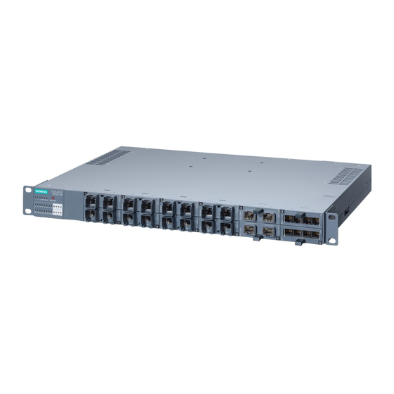
Page 59: Product Group X-300M
4.2.2 Product group X-300M Possible attachments The SCALANCE X308-2M and X308-2M TS are partly modular devices and each has 8 ports. ● 4 fixed ports in the base device: 4 electrical RJ-45 jacks (with securing collar) for connection of end devices or other network segments. - Page 60 The connection of end devices or other network segments does not depend on the module slot, but rather on the selected media module. Refer to the section Media module installation in slot. Example of connections Figure 4-14 SCALANCE X308-2M with MM992-2 and MM991-2 SCALANCE X-300 Operating Instructions, 02/2012, A5E01113043-12...
- Page 61 Description of the device 4.2 Product groups Column Slot number Media MM992-2 MM991-2 modules used Port number P1 * P5 *) P7 *) P2 * P3 * P6 *) P8 *) P4 * Connection type No marking → Fast Ethernet port electrical ) marking →...
-
Page 62: Product Group Xr-300M
Description of the device 4.2 Product groups 4.2.3 Product group XR-300M Possible attachments The SCALANCE XR324-12M is a fully modular device and has 24 ports. ● 0 fixed ports on the base device ● 24 modular ports via module slots: 12 media modules (optical or electrical as required) can be combined using slots (S1- S12) depending on the application. - Page 63 Description of the device 4.2 Product groups Example of a configuration CAUTION Use only approved media modules in the module slots The connection of end devices or other network segments does not depend on the module slot, but rather on the selected media module. Refer to the section Media module installation in slot.
-
Page 64: X-300Eec Product Group
Description of the device 4.2 Product groups 4.2.4 X-300EEC product group 4.2.4.1 Characteristics of the X-300EEC product group Variants The SCALANCE X-300EEC is a 19"/2 device with 9 ports for the connection of end devices or other network segments. There are 2 device types with the following ports: ●... - Page 65 Description of the device 4.2 Product groups Figure 4-17 SCALANCE X302-7EEC (from below) with protective bracket and LC connector Replacing the C-PLUG In the X-300EEC devices, the slot for the C-PLUG is on the top on the housing. Figure 4-18 C-PLUG of the X-300EEC CAUTION The C-PLUG may only be removed or inserted when the power supply to the device is...
- Page 66 Description of the device 4.2 Product groups Terminal block for signaling contact and power supply The terminal block of the X-300EEC for connecting the signaling contact and power supply has the following terminals: ● F1, F2: Signaling contact The 2 signaling contacts on the device version with a redundant power supply are energized in parallel.
- Page 67 Description of the device 4.2 Product groups Ports of the X302-7EEC The SCALANCE X302-7EEC has the following ports: ● 2 electrical gigabit ports (P8 to P9) ● 7 optical Fast Ethernet ports (P1 to P7) Figure 4-19 SCALANCE X302-7EEC Port number Connection type Optical Electrical...
- Page 68 Description of the device 4.2 Product groups Ports of the X307-2EEC The SCALANCE X307-2EEC has the following ports: ● 7 electrical ports (P3 to P9) – 5 Fast Ethernet ports (P3 to P7) – 2 gigabit ports (P8, P9) ● 2 optical Fast Ethernet ports (P1, P2) Figure 4-20 SCALANCE X307-2EEC Port number...
-
Page 69: Xr-300M Eec Product Group
Description of the device 4.2 Product groups 4.2.5 XR-300M EEC product group 4.2.5.1 SCALANCE XR324-4M EEC product characteristics Possible attachments The SCALANCE XR324-4M EEC is a partially modular device and has 24 ports. ● 16 fixed ports in the base device: 16 RJ-45 jacks for connection of end devices or other network segments. - Page 70 Description of the device 4.2 Product groups SCALANCE XR324-4M EEC overview of the variants IE Switch Order number SCALANCE XR324-4M EEC (1 x 24 V … 48 V, cable outlet front) 6GK5 324-4GG00-1ER2 SCALANCE XR324-4M EEC (2 x 24 V … 48 V, cable outlet front) 6GK5 324-4GG00-2ER2 SCALANCE XR324-4M EEC (1 x 100 V to 240 V, cable outlet front) 6GK5 324-4GG00-3ER2...
-
Page 71: Product Group X-300M Poe
SCALANCE X308-2M PoE product characteristics Possible attachments The SCALANCE X308-2M PoE is a partially modular device and has eight ports. ● Four fixed ports in the base device: Four PoE-compliant ports (RJ-45 jacks with securing collars) for connection of end devices or other network segments. - Page 72 The connection of end devices or other network segments does not depend on the module slot, but rather on the selected media module. Refer to the section Media module installation in slot. Example: Fitted with media modules MM992-2 and MM991-2 Figure 4-23 SCALANCE X308-2M PoE with MM992-2 and MM992-2SFP Column Slot number Media MM992-2...
-
Page 73: Product Group Xr-300M Poe
Description of the device 4.2 Product groups 4.2.7 Product group XR-300M PoE 4.2.7.1 SCALANCE XR324-4M PoE product characteristics Possible attachments The SCALANCE XR324-4M PoE is a partially modular device and has 24 ports. ● 16 fixed ports on the base device: –... - Page 74 Description of the device 4.2 Product groups Slot number Media MM991-2 (SC) MM991-2 (SC) modules used Port number P1 * P2 * P3 * P4 * P1*) P2*) P1*) P2*) Slot number Media MM991-2 MM991-2 modules used Port number P9 * P11* ) P12* ) P13*...
-
Page 75: Mm900 Media Modules
Description of the device 4.2 Product groups 4.2.8 MM900 media modules Possible attachments The MM992-2CUC media module has the following: ● 2 x 10/100/1000 Mbps, RJ-45 ports electrical with securing collar Figure 4-25 MM992-2CUC [9922GA] [Device labeling in square brackets] Possible attachments The MM992-2CU media module has the following: ●... -
Page 76: Mm992-2M12 Product Characteristics
Description of the device 4.2 Product groups 4.2.8.1 MM992-2M12 product characteristics Possible attachments The MM992-2M12 media module has the following: ● 2 x 10/100/1000 Mbps, GE M12 connector electrical Figure 4-27 MM992-2M12C [9922HA] [Device labeling in square brackets] Note Only the media module MM992-2SFP may be fitted with approved SFP transceivers. The SFP media module can be fitted with up to two SFPs. - Page 77 Description of the device 4.2 Product groups Possible attachments The MM991-2 media module has the following: ● 2 x100 Mbps, BFOC port optical (multimode, glass) up to max. 3 km Figure 4-29 MM991-2 [9912AB] [Device labeling in square brackets] Possible attachments The MM991-2LD media module has the following: ●...
- Page 78 Description of the device 4.2 Product groups Possible attachments The MM991-2LD (SC) media module has the following: ● 2 x 100 Mbps, SC port optical, (single mode glass), up to max. 26 km Figure 4-32 MM991-2LD (SC) [9912AF] [Device labeling in square brackets] Possible attachments The MM991-2LH+ (SC) media module has the following: ●...
- Page 79 Description of the device 4.2 Product groups Possible attachments The MM992-2LD media module has the following: ● 2 x 1000 Mbps, SC port optical, (single mode glass), up to max. 10 km Figure 4-35 MM992-2LD [9922AM] [Device labeling in square brackets] Possible attachments The MM992-2LH media module has the following: ●...
-
Page 80: General Notes On Mm900
Description of the device 4.2 Product groups Possible attachments The MM992-2ELH media module has the following: ● 2 x 1000 Mbps, SC port optical, (single mode glass), up to max. 120 km Figure 4-38 MM992-2ELH [9922AQ] [Device labeling in square brackets] 4.2.8.2 General notes on MM900 Note... - Page 81 Description of the device 4.2 Product groups The MM900 media module decides what can be connected The connection of end devices or other network segments does not depend on the module slot, but rather on the selected MM900 media module. Possible attachments Figure Electrical RJ-45 ports with securing collar...
-
Page 82: Sfp Transceiver
Description of the device 4.2 Product groups 4.2.9 SFP transceiver Possible attachments The SFP991-1 transceiver has the following: ● 1 x 100 Mbps, LC port optical (multimode, glass) up to max. 3 km Figure 4-39 SFP991-1 Possible attachments The SFP991-1LD transceiver has the following: ●... - Page 83 Description of the device 4.2 Product groups Possible attachments The SFP992-1 transceiver has the following: ● 1 x 1000 Mbps, LC port optical (multimode, glass) up to max. 750 m Figure 4-42 SFP992-1 Possible attachments The SFP992-1LD transceiver has the following: ●...
-
Page 84: General Notes On Sfp
Description of the device 4.2 Product groups Possible attachments The SFP992-1LH+ transceiver has the following: ● 1 x 1000 Mbps, LC port optical (single mode, glass) up to max. 70 km Figure 4-45 SFP992-1LH+ Possible attachments The SFP992-1ELH transceiver has the following: ●... -
Page 85: Interfaces And Signaling Contact Of The Switches
Description of the device 4.3 Interfaces and signaling contact of the switches Note An SFP with multimode has a black clip and an SFP with single mode has a blue clip. To protect the pins, these are fitted with a dummy plug. Interfaces and signaling contact of the switches 4.3.1 Ethernet interfaces - electrical ports... - Page 86 Description of the device 4.3 Interfaces and signaling contact of the switches Transmission medium Data transmission at 10 Mbps and at 100 Mbps is over two wire pairs (pin 1, 2, 3, 6) of the twisted pair cable. For 10 Mbps, at least a category 3 (Cat 3) and for 100 Mbps, at least a four-wire (2 x 2) category 5 (Cat 5) cable is necessary.
-
Page 87: 1000Base-T
Description of the device 4.3 Interfaces and signaling contact of the switches 4.3.1.2 1000Base-T Transmission rate The transmission rate of the electrical Ethernet ports is 10 Mbps, as Fast Ethernet ports 100 Mbps or as gigabit ports 1 Gbps. Transmission mode The transmission mode for 1000Base-T is specified in the IEEE 802.3ab standard. -
Page 88: Power Over Ethernet (Poe)
100 m is used, the connected device can be supplied with a power of 12.95 W. Note The total power provided by the SCALANCE X308-2M PoE on all four PoE ports is a maximum of 30.8 W. The PoE ports meet the conditions listed in the IEEE 802.3af / IEEE 802.3at standard (type 1) for environment A , in other words power supply over Ethernet within a power supply system. -
Page 89: Ports Of The Xr-300M Poe
Description of the device 4.3 Interfaces and signaling contact of the switches Possible attachments The X308-2M PoE is a partially modular device and has 4 fixed ports and 2 slots for media modules. ● 4 electrical ports 4 PoE-compliant RJ-45 jacks with securing collars for connection of end devices or network segments. -
Page 90: Isolation Between The Tp Ports
Description of the device 4.3 Interfaces and signaling contact of the switches Possible attachments The XR324-4M PoE is a partially modular device and has 16 fixed ports and 4 slots for media modules. ● 16 electrical ports – Ports P1 to P8 8 PoE-compliant RJ-45 jacks with securing collars for connection of end devices or network segments –... -
Page 91: Ethernet Interfaces - Optical Ports
Description of the device 4.3 Interfaces and signaling contact of the switches 4.3.2 Ethernet interfaces - optical ports 4.3.2.1 1000Base-SX Transmission rate The transmission rate of the optical gigabit ports is 1 Gbps. Transmission mode Transmission with 1000Base-SX is defined in the IEEE 802.3z standard and is specified as 1000 Mbps transmission rate and full duplex. -
Page 92: Signaling Contact
Description of the device 4.3 Interfaces and signaling contact of the switches Transmission medium Data is transmitted over single mode FOC. The wavelength is 1310 nm or 1550 nm. The core diameter of the single mode FO cable is 9 or 10 µm; the light source is a laser diode. -
Page 93: C-Plug (Configuration Plug)
Description of the device 4.4 C-PLUG (configuration plug) C-PLUG (configuration plug) CAUTION DO NOT REMOVE C-PLUG WHILE POWER IS ON The C-PLUG may only be removed or inserted when the power supply to the device is turned off. In a device with a varnished printed circuit board, you may only use a C-PLUG with a varnished board. - Page 94 Description of the device 4.4 C-PLUG (configuration plug) Inserting in the C-PLUG slot on the IE Switch X-300 Product group Slot Figure C-PLUG X-300 Rear of the device 1. Remove the screw cover. X-300M 2. Insert the C-PLUG in the intended slot. 3.
- Page 95 Description of the device 4.4 C-PLUG (configuration plug) Removing the C-PLUG from the IE Switch X-300 It is only necessary to remove the C-PLUG if the IE Switch develops a fault. The C-PLUG can be removed from the slot using flat pliers, tweezers, or a small screwdriver. Product group Slot Figure...
-
Page 96: Components Of The Product
Description of the device 4.5 Components of the product Components of the product Unpacking, checking 1. Make sure that the package is complete. 2. Check all the parts for transport damage. WARNING Do not use any parts that show evidence of damage! 4.5.1 Components of the product The following components are supplied with a SCALANCE X-300:... -
Page 97: Components Of The Xr-300M Product
Description of the device 4.5 Components of the product Table 4- 1 Overview of the components shipped with the X-300M product group Device: Variant Plug-in terminal block Device Product CD SCALANCE Signaling Power supply contact X308-2M 2-pin 4-pin (24 V) ●... -
Page 98: X-300Eec Product Components
Description of the device 4.5 Components of the product 4.5.4 X-300EEC product components Apart from the device itself, the following components are also supplied with the switch: Table 4- 2 Overview of the components shipped with the X-300EEC product group Device: Components of the product SCALANCE... -
Page 99: Components Of The X308-2M Poe Product
Description of the device 4.5 Components of the product ● Product CD with documentation and software ● With devices with power supply 100 to 240 VAC / 60 to 250 VDC: – A 3-pin terminal block (or two terminal blocks for redundant power supply) for the signaling contacts. -
Page 100: Components Of The Xr-324-4M Poe Product
Description of the device 4.5 Components of the product 4.5.7 Components of the XR-324-4M PoE product Components of the product The following parts ship with a SCALANCE XR-324-4M PoE: ● Device with C-PLUG exchangeable medium ● 2 mounting brackets and 8 screws (M3x5 recessed head, drive: Torx) for 19" rack installation ●... -
Page 101: Components Shipped With The Sfp Product
Description of the device 4.5 Components of the product 4.5.9 Components shipped with the SFP product Table 4- 3 Overview of the components shipped with the SFP product group Device: (Variant) Plug-in terminal block Device Product CD Transceiver (signaling (24V) contact) 4-pin 2-pin... - Page 102 Description of the device 4.5 Components of the product SCALANCE X-300 Operating Instructions, 02/2012, A5E01113043-12...
-
Page 103: Installation
Installation You will find detailed instructions on connecting up the power supply and the signaling contact in the section Connecting (Page 125). WARNING Installation guidelines and safety notices When installing and operating the device, keep to the installation instructions and safety- related notices as described here (section Safety instructions (Page 13)) and in the manual SIMATIC NET Industrial Ethernet Twisted Pair and Fiber Optic Networks (see Preface (Page 3)). -
Page 104: Overview Of The Methods Of Installation
Installation 5.1 Overview of the methods of installation Minimum clearances If you install the IE Switch X-300EEC in enclosures without forced ventilation or cooling, minimum clearances must be maintained to neighboring devices or the wall of the enclosure. By keeping to the minimum clearances, there is then an adequate stream of air for heat dissipation during operation. -
Page 105: Installing A Switch
Installation 5.2 Installing a switch Installing a switch CAUTION Electrical connections Make sure that the power supply of the switch is turned off when fitting the connectors for the power supply and the signaling contacts. For information on the electrical connections, refer to Section Connecting (Page 125). 5.2.1 Installation on a DIN rail WARNING... - Page 106 Installation 5.2 Installing a switch Uninstalling To remove an IE Switch X-300 from the DIN rail: 1. Disconnect all cables from the switch. 2. Release the lower part of the IE Switch X-300 from the DIN rail with a screwdriver and pull the lower part of the switch away from the DIN rail.
-
Page 107: Installation On A Standard Rail
Installation 5.2 Installing a switch 5.2.2 Installation on a standard rail Installation on a SIMATIC S7-300 standard rail 1. Hang the upper guide at the top of the switch housing onto the S7 standard rail. 2. Screw the IE Switch X-300 to the underside of the standard rail. 3. -
Page 108: Wall Mounting
Installation 5.2 Installing a switch Uninstalling To remove an IE Switch X-300 from the SIMATIC S7-300 standard rail, follow these steps: 1. Disconnect all connected cables. 2. Loosen the screws on the underside of the standard rail and lift the IE Switch X-300 away from the rail. -
Page 109: 19" Rack Mounting
Installation 5.2 Installing a switch Note Wall mounting of a rack device For wall mounting of a rack device (R), use suitable fittings such as a mounting bracket. Wall mounting of the IE Switch X-300EEC To mount the IE Switch X-300EEC on a wall, you require an additional securing bracket. You will find the dimensions for a suitable securing bracket in section Graphics (Page 279). - Page 110 Installation 5.2 Installing a switch Minimum clearances If you install the IE Switch in rack devices without forced ventilation or cooling, minimum clearances must be maintained to neighboring devices or the wall of the enclosure. By keeping to the minimum clearances, there is then an adequate stream of air for heat dissipation during operation.
- Page 111 Installation 5.2 Installing a switch Standard position Normal orientation of the device The ventilation grilles are on the top, bottom and sides of the • housing. The LED display is on the left of the front panel of the • housing.
- Page 112 Installation 5.2 Installing a switch 19" rack mounting with standard orientation 19" rack mounting Select the required rack device (R) and the 19" cabinet. Fix the two mounting brackets with 4 screws each to the sides of the housing. The maximum tightening torque for these screws is 0.5 Nm.
- Page 113 Installation 5.2 Installing a switch Desktop operation (only 24 V DC variants with adhesive feet) CAUTION No desktop operation for devices with 100 to 240 V AC power supply Desktop operation is permitted only for the 24 V DC variants of the rack devices (R). The adhesive feet ship with the 24 V DC variants.
-
Page 114: 19" Rack Mounting - X-300Eec Product Group
Installation 5.2 Installing a switch 5.2.5 19" rack mounting - X-300EEC product group The X-300EEC can be installed in a rack singly or as pairs. ● Mounting singly: To do this, an X-300EEC device is secured to a plate and screwed into the 19" rack. ●... -
Page 115: 19" Rack Mounting - Xr-300M Eec Product Group
Installation 5.2 Installing a switch Table 5- 3 Legend for rack mounting of two IE-Switches X-300EEC fastened together Name Plate for side Spring washer Hexagonal nut Side section (the side panel should be under slight tension) IE Switch X-300EEC 5.2.6 19"... - Page 116 Installation 5.2 Installing a switch 19" rack mounting 19" rack mounting is possible for all rack devices identified by (XR). Refer to the technical specifications, Installation options table for each product group. The rack device is installed using two mounting brackets fitted to the front. After fitting the two mounting brackets, the rack device can then be installed in a 19"...
- Page 117 Installation 5.2 Installing a switch Standard position Normal orientation of the device The ventilation grilles are on the top, bottom and sides of the • housing. The LED display is on the left of the front panel of the • housing.
- Page 118 Installation 5.2 Installing a switch 19" rack mounting with standard orientation 19" rack mounting Select the required rack device and the 19" cabinet. Fix the two mounting brackets with 4 screws each to the sides of the housing. The maximum tightening torque for these screws is 0.5 Nm.
-
Page 119: Inserting Media Modules And Sfp Transceivers
Connecting media modules and SFP transceivers CAUTION Use only approved SFPs If you use components not approved by Siemens AG, in particular SFPs, Siemens cannot accept any responsibility for the correct functioning of the "Ethernet switch system" according to the specification. - Page 120 Installation 5.3 Inserting media modules and SFP transceivers CAUTION Remember the orientation of media modules. On modular devices, there are always two module slots arranged opposite each other. Remember the correct orientation when installing MM900 media modules. Example: • The first MM900 media module is installed in slot 3. •...
- Page 121 Installation 5.3 Inserting media modules and SFP transceivers NOTICE Slot number With modular devices, the MM900 media modules must be given a slot number. The slot number labels are supplied with the modular devices. Installing a media module The media module is inserted with the handle pulled out. When the handle is inserted, the media module is locked in the device.
- Page 122 Installation 5.3 Inserting media modules and SFP transceivers Place the media module in the guide rails of the device slot. The media module is correctly installed when it clips easily into the device. Push the handle back into the media module. This locks the media module in the device.
-
Page 123: Sfp Installation In Sfp Media Module
SFP installation in SFP media module WARNING Use only approved SFPs If you use components not approved by Siemens AG, in particular SFPs, Siemens cannot accept any responsibility for the correct functioning of the Ethernet switch system according to the specification. - Page 124 Installation 5.3 Inserting media modules and SFP transceivers Select the required SFP media module in the slot of the device. (Example: X-308-2M, slot 2) Insert the SFP with the clip closed in the SFP media module. Notice: Closing the clip after insertion does not lock the device in the rack.
-
Page 125: Connecting
Connecting WARNING Before connecting up and commissioning the device, read the information in the section Safety instructions (Page 13) NOTICE Commissioning devices with redundancy mechanisms If you use redundancy mechanisms ("HSR" media redundancy or "MRP" and/or redundant coupling of rings over standby coupling), open the redundant path before you insert a new or replacement device in an operational network. -
Page 126: Connecting Media Modules/Sfps
Connecting 6.2 Connecting media modules/SFPs Connecting media modules/SFPs Power supply of the MM900 media modules The MM900 media modules are supplied with power by the switch. Power supply of the SFP transceivers The SFP transceivers are supplied with power via the SFP media module. Connecting the grounding 6.3.1 Connecting the functional ground (XR-300M EEC) -
Page 127: Grounding Of The X-300Eec
Connecting 6.3 Connecting the grounding 6.3.2 Grounding of the X-300EEC Functional ground With the devices X-300EEC and XR-300M EEC with a 100 to 240 VAC / 60 to 250 VDC power supply, functional ground must be connected to the grounding bolts or the power supply terminal of every power supply unit. -
Page 128: Power Supply
Connecting 6.4 Power supply Power supply 6.4.1 24 VDC power supply 6.4.1.1 24 VDC safety extra low voltage 24 V safety extra-low voltage (SELV) WARNING • The IE Switch X-300 is designed for operation with safety extra-low voltage (SELV). This means that only safety extra-low voltages (SELV) complying with IEC950/EN60950/ VDE0805 can be connected to the power supply terminals. - Page 129 Connecting 6.4 Power supply Connecting 24 V safety extra-low voltage (SELV) ● The power supply is connected using a 4-pin plug-in terminal block. ● The power supply can be connected redundantly. Both inputs are isolated. There is no distribution of load. When a redundant power supply is used, the power supply unit with the higher output voltage supplies the IE Switch X-300 alone.
-
Page 130: Vdc - Product Group X-300
Connecting 6.4 Power supply 6.4.1.2 24 VDC - product group X-300 Table 6- 2 Power supply for a SCALANCE X-300 Type 24 V safety extra-low voltage (SELV), redundant X304-2FE ● X306-1LD FE ● X307-3 ● X307-3LD ● X308-2 ● X308-2LD ●... -
Page 131: 24 Vdc - Product Group X-300Eec
Connecting 6.4 Power supply 6.4.1.4 24 VDC - product group X-300EEC Redundancy with the 24...48 V power supply of the IE Switch X-300EEC The X-300EEC is available with a single or redundant power supply unit to supply 24...48 V DC. Each power supply unit is monitored for power failure. The IE Switches X-300EEC therefore provide the following options for redundancy of the 24...48 V DC power supply: ●... - Page 132 Connecting 6.4 Power supply Connecting a redundant power supply to 1 power supply unit Use the left terminal block to connect the power supply. The terminal block is marked "X1": L1 L2 L1 M1 L1 M1 Figure 6-1 Anschluss_1_Netzteil_X-300EEC Assignment of the LED display to the pins for redundant power supply with devices with one power supply unit ●...
-
Page 133: 24 V Product Group Xr300M Poe
Connecting 6.4 Power supply 6.4.1.6 24 V product group XR300M PoE 24 V safety extra-low voltage (SELV) WARNING Safety extra low voltage The equipment is designed for operation with a directly connected safety extra-low voltage (SELV). (This does not apply to 100 V to 240 V devices.) The maximum current via the 24 V terminals is 8 A. -
Page 134: 100 To 240 Vac Power Supply
Connecting 6.4 Power supply Terminal block assignment (4-pin) Table 6- 4 Pinout of the 24 V safety extra-low voltage (SELV) Pin number Assignment Labeling (example) Pin 1 L1+ (24 VDC) Pin 2 Pin 3 Pin 4 L2+ (24 VDC) To wire up the power connector, use a copper cable of category 20-12 AWG or cable with a cross-section of 1.0 to 2.5 mm². -
Page 135: Fitting The Connector For 100 To 240 V Ac
Connecting 6.4 Power supply CAUTION Securing cables with dangerous voltage Make sure that the connector cannot be released accidentally by pulling on the connecting cable. Lay the cables in cable ducts or cable channels and secure the cables, where necessary, with cable ties. CAUTION Securing cables with dangerous voltage Make sure that the connector cannot be released accidentally by pulling on the connecting... - Page 136 Connecting 6.4 Power supply Procedure Follow the steps below to fit the connector to a two-wire cable: 1. Connect the cable to the terminal block. Strip the cable jacket only as far as necessary to be able to strip the insulation and connect up the wires. 2.
-
Page 137: Connecting The 100 To 240 Vac Power Supply
Connecting 6.4 Power supply 6.4.2.2 Connecting the 100 to 240 VAC power supply Connecting the 100 to 240 VAC power supply via the 2-pin terminal block There are devices with single (1 x 100 to 240 V) or redundant power supply (2 x 100 to 240 V). - Page 138 Connecting 6.4 Power supply Grounding WARNING PE connection with X-300EEC and XR-300EEC Grounding simply via the housing is inadequate. For safe operation, the protective ground must be connected to the grounding bolts. On the SCALANCE X-300EEC, the PE connector is on the bottom of the device. On the SCALANCE XR-300M EEC, the PE connector is on the rear of the device between the power connectors.
-
Page 139: Connecting The 100 To 240 V Ac Power Supply With The Xr-300M Poe
Connecting 6.4 Power supply 6.4.2.4 Connecting the 100 to 240 V AC power supply with the XR-300M PoE Connecting to the power supply The devices have a single power supply (1 x 100 to 240 V). The power supply is connected using a 2-pin plug-in terminal block. Terminal block assignment (2-pin) Table 6- 7 Pin assignment of the 100 to 240 VAC power supply... -
Page 140: Signaling Contact
Connecting 6.5 Signaling contact Signaling contact 6.5.1 24 VDC signaling contact The signaling contact is connected to a 2-pin plug-in terminal block. The signaling contact can be subjected to a maximum load of 100 mA (safety extra low voltage SELV 12 VDC / 24 VDC). Table 6- 8 Pin assignment of the signaling contact Pin number... - Page 141 Connecting 6.5 Signaling contact Signaling contact 100 to 240 VAC / 60 to 250 VDC The signaling contact is connected to a 3-pin plug-in terminal block. Table 6- 9 Pin assignment of the 100 to 240 VAC / 60 to 250 VDC signaling contact Pin number Assignment NC contact...
- Page 142 Connecting 6.5 Signaling contact SCALANCE X-300 Operating Instructions, 02/2012, A5E01113043-12...
-
Page 143: Configuration, Displays And Display Elements
Configuration, displays and display elements Assignment of slot numbers CAUTION Specifying the slot number Slots should be numbered in ascending order. Insert a label with the slot number in the slot on the housing starting, for example, with the fixed ports and continuing with the modular ports (with MM900 media modules fitted). Include blind covers and unused slots in the numbering. -
Page 144: Show Location
Configuration, displays and display elements 7.2 Show Location Show Location Localizing an IE Switches X-300 To identify an IE Switch X-300 locally and with certainty, you can use the "show location" function on a programming device to select the node over the network and make it flash. This can be used, for example, when assigning addresses to make sure that the correct node receives the address. - Page 145 Configuration, displays and display elements 7.3 XR-300 diagnostics port Pinout of the RJ-11 jack of the diagnostics port Figure 7-3 RJ-11 jack (schematic) Pin number Pinout of the RJ-11 jack n.c. n.c. TD (Transmit Data) SG (Signal Ground) RD (Receive Data) n.c.
-
Page 146: The Set / Select Button
Configuration, displays and display elements 7.4 The SET / SELECT button Pinout of the XR-300 (connecting cable for the diagnostics port) A connecting cable for the diagnostics port has a 9-pin D-sub female connector for the PC and an RJ-11 plug at the other end. The following table shows the pinout. RJ-11 plug D-sub (9-pin, female) Pin number... -
Page 147: Led Display
Configuration, displays and display elements 7.5 LED display Definition of the fault mask Using the fault mask, you specify an individual "good status" for the connected ports and the power supply. Deviations from this status are then displayed as errors/faults. 1. - Page 148 Configuration, displays and display elements 7.5 LED display The "SB" LED for the standby function This LED shows the status of the standby function. LED color LED status Meaning The standby function is disabled. green The standby function is enabled. The standby section is passive. green flashes The standby function is enabled.
- Page 149 Configuration, displays and display elements 7.5 LED display Selecting the display mode Press the SELECT/SET button to set the required display mode. If the SELECT/SET button is not pressed for longer than a minute, the device automatically changes to display mode A. Pressing SELECT/SET button Status of the "DM"...
- Page 150 Configuration, displays and display elements 7.5 LED display Meaning in display mode D Color Status Meaning L1 / L2 Power supply L1 / L2 is not monitored. If L1 / L2 falls below 17 V * , the signaling contact does not respond. green Power supply L1 / L2 is monitored.
- Page 151 Configuration, displays and display elements 7.5 LED display The P1, P2, ... LEDs for the port status The P1, P2, ... LEDs show information on the status of their respective ports (transmission rate, mode, port monitoring). The meaning of these LEDs depends on the display mode ("DM"...
- Page 152 Configuration, displays and display elements 7.5 LED display SCALANCE X-300 Operating Instructions, 02/2012, A5E01113043-12...
-
Page 153: Technical Specifications
Technical specifications Overview of operating temperatures for SCALANCE X-300 Operating temperature depending on the media modules used The information applies to media modules with product version 2 (PV2): Type Installation Without media MM992-2CUC MM991-2LH+ (SC) Media module Media module location module MM992-2CU MM992-2LH... -
Page 154: X-300 Technical Specifications
Technical specifications 8.2 X-300 technical specifications Type Installation Without media MM992-2CUC MM991-2LH+ (SC) Media module Media module location module MM992-2CU MM992-2LH MM992-2SFP MM992-2SFP MM991-2 MM992-2LH+ with SFP with SFP MM991-2LD MM992-2ELH transceiver transceiver MM991-2 (SC) SFP991-1 SFP991-1LH+ MM991-2LD (SC) SFP991-1LD SFP992-1LH MM992-2 SFP992-1... -
Page 155: Construction, Installation And Environmental Conditions
Technical specifications 8.2 X-300 technical specifications 8.2.1 Construction, installation and environmental conditions Table 8- 1 Construction Device variant Dimensions (W x H x D) Weight Degree of protection X304-2FE, 60 × 125 × 123 mm 700 g IP30 X306-1LD FE X307-3, 120 ×... -
Page 156: Connectors And Electrical Data
Technical specifications 8.2 X-300 technical specifications Table 8- 3 Permitted ambient conditions Device variant Storage/transport Operating temperature Max. relative Max. ambient temperature humidity in temperature at operating operation at 25 °C altitude X304-2FE, -40 °C to +70 °C As of hardware product <... - Page 157 Technical specifications 8.2 X-300 technical specifications Device variant Electrical Optical over twisted pair over fiber-optic cable X308-2LH 7 x RJ-45 jacks with MDI-X assignment 2 x SC duplex sockets 10/100 Mbps (half / full duplex) (1000 Mbps, full duplex to 1000BaseLX) 1 x RJ-45 socket with MDI-X pinning 10/100/1000 Mbps (half/ full duplex)
- Page 158 Technical specifications 8.2 X-300 technical specifications Table 8- 6 Electrical data: Signaling contact Voltage via signaling contact 24 VDC Switching capacity (resistive load) max. 100 mA Table 8- 7 Plug-in terminal block for connectors of the power supply and signaling contact Power supply 1 x 4-pin Signaling contact...
-
Page 159: Cable Lengths
Technical specifications 8.2 X-300 technical specifications Note 2 optical interface transceivers possible (X320-3LD FE) The device is also equipped with 2 optical interface transceivers. Fast Ethernet, long distance interface • Fast Ethernet, multimode interface • As a result, the electrical data in the technical specifications is divided into two parts: transmitter output optical and receiver input. - Page 160 Technical specifications 8.2 X-300 technical specifications Table 8- 11 Permitted cable lengths (fiber-optic cable - Fast Ethernet) Device variant Fiber-optic cable Permitted cable length Attenuation type X304-2FE, 50/125 µm 0 to 5 km ≤1 dB/km at 1 310 nm; 1 200 MHz×km; maximum X320-1 FE multimode fiber insertion loss 0.5 dB;...
-
Page 161: Other Properties
Technical specifications 8.2 X-300 technical specifications 8.2.4 Other properties Table 8- 13 Switching properties Max. number of learnable addresses 8 000 Aging time 30 sec Switching technique Store and forward Latency 5 μs Table 8- 14 Reconfiguration times for redundancy mechanisms Redundancy mechanism Reconfiguration times 300 ms... - Page 162 Technical specifications 8.2 X-300 technical specifications Table 8- 16 Full wire speed switching Number of frames per second At a frame length of At 100 Mbps At 1000 Mbps 148810 1488095 64 bytes 84459 844595 128 bytes 45290 452899 256 bytes 23496 234962 512 bytes...
-
Page 163: X-300M Technical Specifications
Technical specifications 8.3 X-300M technical specifications X-300M technical specifications Note Validity of the technical specifications All the technical specifications described in this section that is not assigned to a specific device variant, version or a media module, apply to all device variants/versions of the product group. - Page 164 Technical specifications 8.3 X-300M technical specifications Table 8- 19 Permitted ambient conditions Media module Storage/transport Operating temperature Max. relative humidity Max. ambient temperature in operation at 25 °C temperature at operating altitude Without media module -40 °C to +70 °C Horizontal installation: <...
-
Page 165: Connectors And Electrical Data
Technical specifications 8.3 X-300M technical specifications 8.3.2 Connectors and electrical data Table 8- 20 Connection for end devices or network components Max. number 8 ports Electrical (via twisted-pair) 4 x RJ-45 jacks with MDI-X assignment 10/100/1000 Mbps (half / full duplex) Media module slots 4 x modular (2 ports per slot) -
Page 166: Cable Lengths
Technical specifications 8.3 X-300M technical specifications Table 8- 25 Plug-in terminal block for connectors of the power supply and signaling contact Device version Power supply Signaling contact (power supply) 12 VDC 1 x 4-pin 1 x 2-pin 24 VDC 1 x 4-pin 1 x 2-pin 8.3.3 Cable lengths... -
Page 167: Other Properties
Technical specifications 8.3 X-300M technical specifications 8.3.4 Other properties Table 8- 28 Switching properties Max. number of learnable addresses 8 000 Aging time 30 sec Switching technique Store and forward Latency 5 μs Table 8- 29 Reconfiguration times for redundancy mechanisms Redundancy mechanism Reconfiguration times 300 ms... - Page 168 Technical specifications 8.3 X-300M technical specifications Table 8- 31 Full wire speed switching Number of frames per second At a frame length of At 100 Mbps At 1000 Mbps 148810 1488095 64 bytes 84459 844595 128 bytes 45290 452899 256 bytes 23496 234962 512 bytes...
-
Page 169: Xr-300M Technical Specifications
Technical specifications 8.4 XR-300M technical specifications XR-300M technical specifications Note Validity of the technical specifications All the technical specifications described in this section that is not assigned to a specific device variant, version or a media module, apply to all device variants/versions of the product group. - Page 170 Technical specifications 8.4 XR-300M technical specifications Table 8- 34 Permitted environmental conditions depending on the media modules used Media module Storage/transport Operating temperature Max. relative Max. ambient temperature humidity in temperature at operating operation at 25 °C altitude MM991-2, -40 °C to +70 °C Horizontal installation: <...
-
Page 171: Connectors And Electrical Data
Technical specifications 8.4 XR-300M technical specifications 8.4.2 Connectors and electrical data Table 8- 35 Connection for end devices or network components Max. number 24 ports Media module slots 12 x modular (2 ports per slot) Transmitter output (optical) and receiver input The values correspond to those of the permitted MM900 media modules and SFP transceivers. -
Page 172: Cable Lengths
Technical specifications 8.4 XR-300M technical specifications Table 8- 40 Plug-in terminal block for connectors of the power supply and signaling contact Device version Power supply Signaling contact (power supply) 2 x 24 VDC 2 x 4-pin 2 x 2-pin 1 x 100 to 240 VAC 1 x 2-pin 1 x 2-pin 8.4.3... -
Page 173: Block Architecture
Technical specifications 8.4 XR-300M technical specifications 8.4.4 Block architecture Block architecture with SCALANCE XR-300 devices The XR324-12M and XR324-4M handle the Ethernet frame traffic of the 24 ports with the aid of three switch blocks. ● The three switch blocks are connected in series (block 1 via block 2 to block 3) ●... -
Page 174: Other Properties
Technical specifications 8.4 XR-300M technical specifications 8.4.5 Other properties Table 8- 43 Switching properties Max. number of learnable addresses 8 000 Aging time 30 sec Switching technique Store and forward Latency 5 μs Table 8- 44 Reconfiguration times for redundancy mechanisms Redundancy mechanism Reconfiguration times 300 ms... -
Page 175: Technical Specifications For X-300Eec
Technical specifications 8.5 Technical specifications for X-300EEC Note The following applies to IE Switches X-300: The number of IE Switches X-300 connected in a line influences the frame delay time. When a frame passes through the switch, this is delayed by the Store&Forward function of the IE Switch X-300 by the following values: •... -
Page 176: Construction, Installation And Environmental Conditions
Technical specifications 8.5 Technical specifications for X-300EEC 8.5.1 Construction, installation and environmental conditions Table 8- 47 Construction Device version Dimensions (W x H x D) Weight Degree of protection (power supply) 1 24 VDC power supply unit • 1 800 g IP30 Without clip: 60 ×... - Page 177 Technical specifications 8.5 Technical specifications for X-300EEC Table 8- 50 Mechanical stability Strain withstood / category Test conditions (standard) Vibration Frequency range 10 Hz to 150 Hz: (IEC 60068-2-6) Transit frequency: 58 Hz to 60 Hz • Peak value of the displacement [mm] below the transit •...
-
Page 178: Connectors And Electrical Data
Technical specifications 8.5 Technical specifications for X-300EEC 8.5.2 Connectors and electrical data Table 8- 51 Connection for end devices or network components Device variant Electrical Optical over twisted pair over fiber-optic cable X302-7EEC 2 x RJ-45 jacks with MDI-X assignment 7 x LC sockets multimode (all variants) 10/100/1000 Mbps (half / full duplex) - Page 179 Technical specifications 8.5 Technical specifications for X-300EEC Table 8- 54 Electrical data: Overcurrent protection Device version Overcurrent protection of the power supply Non-replaceable fuse (power supply) 1 power supply unit 24 to 48 VDC 1 x T4A / 125 V 2 power supply units 24 to 48 VDC 2 x T4A / 125 V 1 x power supply unit 100 to 240 VAC /...
-
Page 180: Cable Lengths
Technical specifications 8.5 Technical specifications for X-300EEC Table 8- 58 Overvoltage category General Overvoltage category II In the application range of EN 60255-27 Overvoltage category III 8.5.3 Cable lengths Table 8- 59 Permitted cable lengths (copper cable - Fast Ethernet) Cable type Accessory (plug, outlet, Permitted cable length... -
Page 181: Other Properties
Technical specifications 8.5 Technical specifications for X-300EEC 8.5.4 Other properties Table 8- 62 Switching properties Max. number of learnable addresses 8 000 Aging time 30 sec Switching technique Store and forward Latency 5 μs Table 8- 63 Reconfiguration times for redundancy mechanisms Redundancy mechanism Reconfiguration times 300 ms... - Page 182 Technical specifications 8.5 Technical specifications for X-300EEC Table 8- 65 Full wire speed switching Number of frames per second At a frame length of At 100 Mbps At 1000 Mbps 148810 1488095 64 bytes 84459 844595 128 bytes 45290 452899 256 bytes 23496 234962...
-
Page 183: Xr-300M Eec Technical Specifications
Technical specifications 8.6 XR-300M EEC technical specifications XR-300M EEC technical specifications Note Validity of the technical specifications All the technical specifications described in this section that is not assigned to a specific device variant, version or a media module, apply to all device variants/versions of the product group. - Page 184 Technical specifications 8.6 XR-300M EEC technical specifications Table 8- 68 Permitted environmental conditions depending on the media modules used Media module Storage/transport Operating temperature Max. relative Max. ambient temperature humidity in temperature at operating operation at 25 °C altitude Without media module -40 °C to +70 °C Horizontal installation: <...
- Page 185 Technical specifications 8.6 XR-300M EEC technical specifications Media module Storage/transport Operating temperature Max. relative Max. ambient temperature humidity in temperature at operating operation at 25 °C altitude MM992-2SFP and the -40 °C to +70 °C Horizontal installation: < 95 % (no Horizontal installation: following SFP -40 °C to +70 °C...
-
Page 186: Connectors And Electrical Data
Technical specifications 8.6 XR-300M EEC technical specifications 8.6.2 Connectors and electrical data Table 8- 69 Connection for end devices or network components Max. number 24 ports Electrical 16 x RJ-45 jacks 10/100/1000 Mbps Media module slots 4 x modular (2 ports per slot) Transmitter output (optical) and receiver input The values correspond to those of the permitted MM900 media modules and SFP transceivers. - Page 187 Technical specifications 8.6 XR-300M EEC technical specifications Table 8- 72 Electrical data: Overcurrent protection Device version Overcurrent protection of the power supply Non-replaceable fuse (power supply) 1 x 24 to 48 VDC 1 x T2H / 250 V 2 x 24 to 48 VDC 2 x T2H / 250 V 1 x 100 to 240 VAC / 1 x T2H / 250 V (AC)
-
Page 188: Cable Lengths
Technical specifications 8.6 XR-300M EEC technical specifications 8.6.3 Cable lengths Table 8- 76 Permitted cable lengths (copper cable - Fast Ethernet) Cable type Accessory (plug, outlet, Permitted cable length TP cord) IE TP torsion cable with IE FC Outlet RJ-45 0 to 45 m + 10 m TP cord + 10 m TP cord... -
Page 189: Block Architecture
Technical specifications 8.6 XR-300M EEC technical specifications 8.6.4 Block architecture Block architecture with SCALANCE XR-300 devices The XR324-12M and XR324-4M handle the Ethernet frame traffic of the 24 ports with the aid of three switch blocks. ● The three switch blocks are connected in series (block 1 via block 2 to block 3) ●... -
Page 190: Other Properties
Technical specifications 8.6 XR-300M EEC technical specifications 8.6.5 Other properties Table 8- 78 Switching properties Max. number of learnable addresses 8 000 Aging time 30 sec Switching technique Store and forward Latency 5 μs Table 8- 79 Reconfiguration times for redundancy mechanisms Redundancy mechanism Reconfiguration times 300 ms... -
Page 191: X-300M Poe Technical Specifications
Technical specifications 8.7 X-300M PoE technical specifications Note The following applies to IE Switches X-300: The number of IE Switches X-300 connected in a line influences the frame delay time. When a frame passes through the switch, this is delayed by the Store&Forward function of the IE Switch X-300 by the following values: •... - Page 192 Technical specifications 8.7 X-300M PoE technical specifications Table 8- 84 Permitted ambient conditions Media module Storage/transport Operating temperature Max. relative Max. ambient temperature humidity in operation temperature at operating at 25 °C altitude Without media module -40 °C to +70 °C Horizontal installation: <...
- Page 193 Technical specifications 8.7 X-300M PoE technical specifications Media module Storage/transport Operating temperature Max. relative Max. ambient temperature humidity in operation temperature at operating at 25 °C altitude MM992-2SFP and the -40 °C to +70 °C Horizontal installation: < 95 % (no Horizontal installation: following SFP -40 °C to +60 °C...
-
Page 194: Connectors And Electrical Data
Technical specifications 8.7 X-300M PoE technical specifications 8.7.2 Connectors and electrical data Table 8- 85 Connection for end devices or network components Max. number 8 ports Electrical 4 x RJ-45 jacks, MDI-X pinning, 10/100/1000 Mbps (half/full duplex) power supply for connected devices (PDs) using Power over Ethernet (PoE) according to IEEE 802.3af / 802.3at (type 1) Media module slots... - Page 195 Technical specifications 8.7 X-300M PoE technical specifications Table 8- 89 Power over Ethernet at port P1, P2, P3, P4 PoE function within a power supply system According to IEEE 802.3af / 802.3at (type 1) for environment A Method of PoE power feed Alternative A (refer to the following table for the pin assignment)
-
Page 196: Cable Lengths
Technical specifications 8.7 X-300M PoE technical specifications 8.7.3 Cable lengths Table 8- 92 Permitted cable lengths (copper cable - Fast Ethernet) Cable type Accessory (plug, outlet, Permitted cable length TP cord) IE TP torsion cable with IE FC Outlet RJ-45 0 to 45 m + 10 m TP cord + 10 m TP cord... -
Page 197: Other Properties
Technical specifications 8.7 X-300M PoE technical specifications 8.7.4 Other properties Table 8- 94 Switching properties Max. number of learnable addresses 8 000 Aging time 30 sec Switching technique Store and forward Latency 5 μs Table 8- 95 Reconfiguration times for redundancy mechanisms Redundancy mechanism Reconfiguration times 300 ms... -
Page 198: Xr-300M Poe Technical Specifications
Technical specifications 8.8 XR-300M PoE technical specifications Note The following applies to IE Switches X-300: The number of IE Switches X-300 connected in a line influences the frame delay time. When a frame passes through the switch, this is delayed by the Store&Forward function of the IE Switch X-300 by the following values: •... -
Page 199: Construction, Installation And Environmental Conditions
Technical specifications 8.8 XR-300M PoE technical specifications 8.8.1 Construction, installation and environmental conditions Table 8- 98 Construction Dimensions (W x H x D) 449 × 43.6 × 305 mm Weight 6 800 g Degree of protection IP20 (with closed service panel) Table 8- 99 Installation options Device version... -
Page 200: Connectors And Electrical Data
Technical specifications 8.8 XR-300M PoE technical specifications Media module Storage/transport Operating temperature Max. relative Max. ambient temperature humidity in temperature at operating operation at 25 °C altitude MM992-2SFP and the -40 °C to +70 °C Horizontal installation: < 95 % (no Horizontal installation: following SFP -40 °C to +60 °C... - Page 201 Technical specifications 8.8 XR-300M PoE technical specifications Table 8- 102 Electrical data: Power supply Device version Redundant Redundant power Power supply (power supply) power supply unit supply possible 24 VDC 12 VDC (19.2 to 28.8 VDC) 100 to 240 VAC 100 to 240 VAC (85 to 264 V) Table 8- 103 Electrical data: Current consumption and power loss...
- Page 202 Technical specifications 8.8 XR-300M PoE technical specifications Table 8- 107 Power over Ethernet at port P1 to P8 PoE function within a power supply system According to IEEE 802.3af / 802.3at (type 1) for environment A Method of PoE power feed Alternative A (refer to the following table for the pin assignment)
-
Page 203: Cable Lengths
Technical specifications 8.8 XR-300M PoE technical specifications 8.8.3 Cable lengths Table 8- 110 Permitted cable lengths (copper cable - Fast Ethernet) Cable type Accessory (plug, outlet, Permitted cable length TP cord) IE TP torsion cable with IE FC Outlet RJ-45 0 to 45 m + 10 m TP cord + 10 m TP cord... -
Page 204: Block Architecture
Technical specifications 8.8 XR-300M PoE technical specifications 8.8.4 Block architecture Block architecture of the SCALANCE XR-300M PoE The XR-300M PoE handles the Ethernet frame traffic of the 24 ports with the aid of three switch blocks. ● The three switch blocks are connected in series (block 1 via block 2 to block 3). ●... -
Page 205: Other Properties
Technical specifications 8.8 XR-300M PoE technical specifications 8.8.5 Other properties Table 8- 112 Switching properties Max. number of learnable addresses 8 000 Aging time 30 sec Switching technique Store and forward Latency 5 μs Table 8- 113 Reconfiguration times for redundancy mechanisms Redundancy mechanism Reconfiguration times 300 ms... -
Page 206: Mm900 Technical Specifications
Technical specifications 8.9 MM900 technical specifications MM900 technical specifications Note Validity of the technical specifications All the technical specifications described in this section that are not specific to a product version, apply to the MM900 media module. 8.9.1 Construction, installation and environmental conditions Table 8- 116 Construction Dimensions (W x H x D) 60 ×... - Page 207 Technical specifications 8.9 MM900 technical specifications Type Installation Without MM992-2CUC MM991-2LH+ Media module Media module MM992-2SFP location media MM992-2CU (SC) MM992-2SFP module MM992-2M12 MM992-2LH with SFP with SFP MM991-2 MM992-2LH+ transceiver transceiver MM991-2LD MM992-2ELH SFP991-1 SFP991-1LH+ MM991-2 (SC) SFP991-1LD SFP992-1LH MM991-2LD (SC) SFP992-1 SFP992-1LH+...
-
Page 208: Connectors And Electrical Data
Technical specifications 8.9 MM900 technical specifications 8.9.2 Connectors and electrical data Table 8- 119 Interfaces Product variant Interfaces MM992-2CUC 2 x 10/100/1000 Mbps, RJ-45 ports electrical with securing collar MM992-2CU 2 x 10/100/1000 Mbps, RJ-45 port electrical without securing collar MM992-2M12 2 x 10/100/1000 Mbps, GE M12 connector electrical MM991-2... - Page 209 Technical specifications 8.9 MM900 technical specifications Table 8- 121 Electrical data: Current consumption and power loss I Product variant Current consumption Effective power loss MM992-2CUC 70 mA 1.65 W MM992-2CU 70 mA 1.65 W MM992-2M12 70 mA 1.65 W MM991-2 100 mA 2.42 W MM991-2LD...
-
Page 210: Cable Lengths
Technical specifications 8.9 MM900 technical specifications Table 8- 123 Electrical data: Transmitter output (optical) and receiver input Product variant Transmitter output (optical) Receiver input min. [dBm] max. [dBm] Sensitivity min. [dBm] Input power max. [dBm] MM992-2CUC MM992-2CU MM992-2M12 MM991-2 MM991-2LD MM991-2 (SC) MM991-2LD (SC) MM991-2LH+ (SC) - Page 211 Technical specifications 8.9 MM900 technical specifications Table 8- 125 Permitted cable lengths (fiber-optic cable - Fast Ethernet) Product variant Fiber-optic cable Max. permittted Attenuation type cable length MM991-2 50/125 µm 5 km ≤1 dB/km at 1 310 nm; 1 200 MHz×km; maximum multimode fiber insertion loss 0.5 dB;...
-
Page 212: Other Properties
Technical specifications 8.9 MM900 technical specifications Table 8- 126 Permitted cable lengths (copper cable/fiber-optic cable) for the SFP media module Product variant Max. permittted cable length MM992-2SFP Depending on the SFP transceiver used. You will find further information in the compact operating instructions "Transceiver SFP/SFP+". -
Page 213: Sfp Technical Specifications
Technical specifications 8.10 SFP technical specifications 8.10 SFP technical specifications 8.10.1 SFP construction, installation and environment Table 8- 128 Construction Device: (Variant) Dimensions (W x H x D) Weight IP degree of [in g] protection Transceiver [in mm] SFP991-1 (1 x 100 Mbps, LC port 13.7 x 11.9 x 56.5 IP20 optical, multimode glass,... - Page 214 Technical specifications 8.10 SFP technical specifications Table 8- 129 Installation options (modular) Device: (Variant) Modular installation options: Transceiver Media module installation in slot SFP installation in SFP media module SFP991-1 (1 x 100 Mbps, LC port optical, ● multimode glass, up to max. 3 km) SFP991-1LD (1 x 100 Mbps, LC port optical, single ●...
- Page 215 Technical specifications 8.10 SFP technical specifications Table 8- 130 Permitted ambient conditions Device: (Variant) Operating Storage/transport Relative humidity Operating transceiver temperature temperature at 25 °C during altitude at max. operation, xx °C ambient maximum temperature SFP991-1 (1 x 100 Mbps, LC port optical, -40 °C through -40 °C to +85 °C ‹...
-
Page 216: Sfp Connectors And Electrical Data
Technical specifications 8.10 SFP technical specifications 8.10.2 SFP connectors and electrical data Table 8- 131 Connection of end devices or network components Device: (Variant) Connection of end devices or network components Transceiver Max. of which: number electrical - optical over FO cable Single Multi mode... - Page 217 Technical specifications 8.10 SFP technical specifications Table 8- 132 Electrical data: Power supply, current consumption and power loss Device: (Variant) Effective power loss *) Transceiver SFP991-1 (1 x 100 Mbps, LC port 0.36 W optical, multimode glass, up to max. 3 km) SFP991-1LD (1 x 100 Mbps, LC port 0.39 W...
- Page 218 Technical specifications 8.10 SFP technical specifications Table 8- 133 Electrical data: Transmitter output optical and receiver input Device: (Variant) Transmitter output optical Receiver input Transceiver min. max. Sensitivity min. max. input power [dBm] [dBm] [dBm] [dBm] SFP991-1 (1 x 100 Mbps, LC port optical, multimode glass, up to max.
-
Page 219: Cable Lengths For Sfp
Technical specifications 8.10 SFP technical specifications 8.10.3 Cable lengths for SFP Table 8- 134 Permitted cable lengths (fiber-optic) Fast Ethernet Device: (Variant) Fiber FO cable lengths transceiver SFP991-1 (1 x 100 Mbps, LC port 50/125 µm multimode 0-3km optical, multimode glass, up fiber (1 dB/km at 1310 nm;... - Page 220 Technical specifications 8.10 SFP technical specifications Table 8- 135 Permitted cable lengths (fiber-optic) gigabit Device: (Variant) Fiber FO cable lengths transceiver SFP992-1 (1 x 1000 Mbps, LC port 62.5/125 µm 0-350m optical, multimode glass, up multimode fiber (3.1 dB/km at 850 nm; to max.
-
Page 221: Other Properties Of Sfp
Technical specifications 8.10 SFP technical specifications 8.10.4 Other properties of SFP Table 8- 136 MTBF Device: (Variant) MTBF transceiver SFP991-1 (1 x 100 Mbps, LC port > 120 years optical, multimode glass, up to max. 3 km) SFP991-1LD (1 x 100 Mbps, LC port >... - Page 222 Technical specifications 8.10 SFP technical specifications Table 8- 137 Full wire speed switching Number of frames At a frame length of (in bytes): at 100 Mbps at 1000 Mbps 148810 1488095 84459 844595 45290 452899 23496 234962 11973 119732 1024 9615 96154 1280...
-
Page 223: Approvals, Certificates, Standards
Approvals, certificates, standards X-300 product group 9.1.1 Approvals, Certificates Note The specified approvals apply only when the corresponding mark is printed on the product. You can check which of the following approvals have been granted for your product by the markings on the type plate. - Page 224 The current descriptions of the currently available products can always be found on the Internet under the specified entry IDs/Internet pages: – SIMATIC NET Industrial Twisted Pair and Fiber Optic Networks Manual 8763736 (http://support.automation.siemens.com/WW/view/en/8763736) – EMC Installation Guideline, Planning Guide 28518276 (http://support.automation.siemens.com/WW/view/en/28518276) ●...
- Page 225 • "Approval of SIMATIC/ SIMATIC NET Products for Direct Installation in Ex-Zone 2" You will find this on the Internet on the pages of Siemens Industry Automation Customer Support under the following entry ID: 33118441 (http://support.automation.siemens.com/WW/view/en/33118441)
-
Page 226: X-300 Type Plate
Approvals, certificates, standards 9.1 X-300 product group cULus Approval for Industrial Control Equipment cULus Listed 69B1 Underwriters Laboratories Inc. complying with ● UL 508 ● CSA C22.2 No. 142-M1987 cULus Approval Hazardous Location cULus Listed 21BP I. T. E. FOR HAZ. LOC. Underwriters Laboratories Inc. -
Page 227: X-300 Declaration Of Conformity
X-300 declaration of conformity Declaration of Conformity You will find the EC Declaration of Conformity for these products on the Internet at the following address: http://support.automation.siemens.com/WW/view/en/33118441 (http://support.automation.siemens.com/WW/view/en/33118441) --> Entry list --> Entry type "Certificates" --> Certificate type "Declaration of Conformity"... -
Page 228: Overview Of The X-300 Approvals
Approvals, certificates, standards 9.1 X-300 product group 9.1.5 Overview of the X-300 approvals Table 9- 1 Overview of the approvals Type c-UL-us c-UL-us C-TICK ATEX95 for hazardous Zone 2 locations UL 60950 1 UL1604 and FM 3611 AS/NZS 2064 EN 61000-6-4 EN 60079- UL2279 or (Class A). -
Page 229: Mechanical Stability (In Operation)
Approvals, certificates, standards 9.2 Product group X-300M 9.1.6 X-300 mechanical stability (in operation) Type IEC 60068-2-6 vibration IEC 60068-2-27 shock 5 – 9 Hz: 3.5 mm 15 g, 11 ms duration 9 – 150 Hz: 1 g 6 shocks per axis 1 octave/min, 20 sweeps X304-2FE ●... - Page 230 The current descriptions of the currently available products can always be found on the Internet under the specified entry IDs/Internet pages: – SIMATIC NET Industrial Twisted Pair and Fiber Optic Networks Manual 8763736 (http://support.automation.siemens.com/WW/view/en/8763736) – EMC Installation Guideline, Planning Guide 28518276 (http://support.automation.siemens.com/WW/view/en/28518276) ●...
- Page 231 • "Approval of SIMATIC/ SIMATIC NET Products for Direct Installation in Ex-Zone 2" You will find this on the Internet on the pages of Siemens Industry Automation Customer Support under the following entry ID: 33118441 (http://support.automation.siemens.com/WW/view/en/33118441)
- Page 232 Approvals, certificates, standards 9.2 Product group X-300M FM approval The product meets the requirements of the standards ● Factory Mutual Approval Standard Class Number 3611 ● FM Hazardous (Classified) Location Electrical Equipment: Non Incendive / Class I / Division 2 / Groups A,B,C,D / T4 and Non Incendive / Class I / Zone 2 / Group IIC / T4 Notice for Australia The product meets the requirements of the AS/NZS 2064 standard (Class A).
-
Page 233: X-300M Type Plate
X-300M conformity certificates Declaration of Conformity You will find the EC Declaration of Conformity for these products on the Internet at the following address: http://support.automation.siemens.com/WW/view/en/33118441 --> Entry list --> Entry type "Certificates" --> Certificate type "Declaration of Conformity" Example German: "EG-Konformitätserklärung SCALANCE X310", Example English: "Declaration of Conformity SCALANCE X310". -
Page 234: X-300M Fda And Iec Approvals
Approvals, certificates, standards 9.2 Product group X-300M 9.2.4 X-300M FDA and IEC approvals The following devices meet the FDA and IEC requirements listed below: Product line Product Device: (Variant) Fulfills FDA and IEC group requirements SCALANCE X-300 X-300M X308-2M X-300 X-300M X308-2M TS Note: In the modular devices (M), the marking is provided by the MM900 media modules and the SFP transceivers. -
Page 235: Overview Of X-300M Approvals
Approvals, certificates, standards 9.2 Product group X-300M 9.2.5 Overview of X-300M approvals Table 9- 2 Overview of the approvals Device: (Variant) c-UL-us c-UL-us C-TICK ATEX95 SCALANCE Zone 2 hazardous locations UL 60950 UL1604 and FM 3611 AS/NZS EN 60079- UL2279 or 2064 61000- 15:2005 , EN... -
Page 236: X-300M Mechanical Stability (In Operation)
Approvals, certificates, standards 9.3 Product group XR-300M 9.2.6 X-300M mechanical stability (in operation) Device: (Variant) IEC 60068-2-6 vibration IEC 60068-2-27 shock SCALANCE 5 – 9 Hz: 3.5 mm 15 g, 11 ms duration 9 – 150 Hz: 1 g 6 shocks per axis 1 octave/min, 20 sweeps X308-2M ●... - Page 237 The current descriptions of the currently available products can always be found on the Internet under the specified entry IDs/Internet pages: – SIMATIC NET Industrial Twisted Pair and Fiber Optic Networks Manual 8763736 (http://support.automation.siemens.com/WW/view/en/8763736) – EMC Installation Guideline, Planning Guide 28518276 (http://support.automation.siemens.com/WW/view/en/28518276) ●...
- Page 238 • "Approval of SIMATIC/ SIMATIC NET Products for Direct Installation in Ex-Zone 2" You will find this on the Internet on the pages of Siemens Industry Automation Customer Support under the following entry ID: 33118441 (http://support.automation.siemens.com/WW/view/en/33118441)
- Page 239 Approvals, certificates, standards 9.3 Product group XR-300M cULus Approval for Information Technology Equipment All variants of the XR-300M EEC with 24 VDC power supply meet the requirements cULus Listed I. T. E. Underwriters Laboratories Inc. complying with ● UL 60950-1 (Information Technology Equipment) ●...
-
Page 240: Xr-300M Type Plate
XR-300M conformity certificate Declaration of Conformity You will find the EC Declaration of Conformity for these products on the Internet at the following address: http://support.automation.siemens.com/WW/view/en/33118441 --> Entry list --> Entry type "Certificates" --> Certificate type "Declaration of Conformity" Example German: "EG-Konformitätserklärung SCALANCE X310", Example English: "Declaration of Conformity SCALANCE X310". -
Page 241: Xr-300M Fda And Iec Approvals
Approvals, certificates, standards 9.3 Product group XR-300M 9.3.4 XR-300M FDA and IEC approvals The following devices meet the FDA and IEC requirements listed below: Product line Product Device: Variant Fulfills FDA and IEC group requirements SCALANCE X-300 XR-300M XR324-12M 2 x 24 V DC, cable outlet front XR324-12M 1 x 100 to 240 V AC, cable outlet front... -
Page 242: Xr-300M Mechanical Stability (In Operation)
Approvals, certificates, standards 9.3 Product group XR-300M Table 9- 3 Overview of the approvals Device: (Variant) c-UL-us c-UL-us C-TICK ATEX95 SCALANCE Zone 2 (*) hazardous locations (*) UL 60950 UL1604 and FM 3611 AS/NZS EN 60079- UL2279 or 2064 61000- 15:2005 , EN CL.1, Div.2 GP. -
Page 243: X-300Eec Product Group
Approvals, certificates, standards 9.4 X-300EEC product group X-300EEC product group 9.4.1 X-300EEC approvals and certificates NOTICE Issued approvals on the type plate of the device The specified approvals apply only when the corresponding mark is printed on the product. You can check which of the following approvals have been granted for your product by the markings on the type plate. - Page 244 The very latest documentation is available on the Internet! You will find the installation instructions documentation on the Internet on the pages of Siemens Industry Automation Customer Support under the following entry ID: – SIMATIC NET Industrial Twisted Pair and Fiber Optic Networks Manual 8763736 (http://support.automation.siemens.com/WW/view/en/8763736)
- Page 245 • "Approval of SIMATIC/ SIMATIC NET Products for Direct Installation in Ex-Zone 2" You will find this on the Internet on the pages of Siemens Industry Automation Customer Support under the following entry ID: 33118441 (http://support.automation.siemens.com/WW/view/en/33118441)
- Page 246 Approvals, certificates, standards 9.4 X-300EEC product group IEEE 1613 The product meets the requirements of the standard IEEE 1613 CLASS 1 (electrical ports) or IEEE 1613 CLASS 2 (optical ports). FM approval All variants of the X-300EEC with power supply 24 V DC have the following approval: ●...
-
Page 247: X-300Eec Declaration Of Conformity
X-300EEC declaration of conformity Declaration of Conformity You will find the EC Declaration of Conformity for these products on the Internet at the following address: http://support.automation.siemens.com/WW/view/en/33118441 --> Entry list --> Entry type "Certificates" --> Certificate type "Declaration of Conformity" Example German: "EG-Konformitätserklärung SCALANCE X310", Example English: "Declaration of Conformity SCALANCE X310". -
Page 248: X-300Eec Mechanical Stability (In Operation)
Approvals, certificates, standards 9.5 XR-300M EEC product group 9.4.4 X-300EEC mechanical stability (in operation) All variants of the IE Switch SCALANCE X-300EEC meet the following requirements for mechanical stability: ● IEC 60068-2-6 (vibration) 5 – 9 Hz: 3.5 mm 9 – 150 Hz: 1 g 1 octave/min, 20 sweeps ●... - Page 249 The current descriptions of the currently available products can always be found on the Internet under the specified entry IDs/Internet pages: – SIMATIC NET Industrial Twisted Pair and Fiber Optic Networks Manual 8763736 (http://support.automation.siemens.com/WW/view/en/8763736) – EMC Installation Guideline, Planning Guide 28518276 (http://support.automation.siemens.com/WW/view/en/28518276) ●...
- Page 250 • "Approval of SIMATIC/ SIMATIC NET Products for Direct Installation in Ex-Zone 2" You will find this on the Internet on the pages of Siemens Industry Automation Customer Support under the following entry ID: 33118441 (http://support.automation.siemens.com/WW/view/en/33118441)
- Page 251 Approvals, certificates, standards 9.5 XR-300M EEC product group FM approval All variants of the XR-300M EEC with 24 VDC power supply meet the requirements of the standards ● Factory Mutual Approval Standard Class Number 3611 ● FM Hazardous (Classified) Location Electrical Equipment: Non Incendive / Class I / Division 2 / Groups A,B,C,D / T4 and Non Incendive / Class I / Zone 2 / Group IIC / T4 Notice for Australia...
-
Page 252: Xr-300M Eec Declaration Of Conformity
XR-300M EEC declaration of conformity Conformity certificate You will find the EC Declaration of Conformity for these products on the Internet at the following address: http://support.automation.siemens.com/WW/view/en/33118441 --> Entry list --> Entry type "Certificates" --> Certificate type "Declaration of Conformity" Example German: "EG-Konformitätserklärung SCALANCE X310", Example English: "Declaration of Conformity SCALANCE X310". - Page 253 Approvals, certificates, standards 9.5 XR-300M EEC product group Table 9- 6 Overview of the approvals Device: (Variant) c-UL-us c-UL-us C-TICK ATEX95 SCALANCE Zone 2 hazardous locations UL 60950 ANSI / ISA FM 3611 AS/NZS EN 60079- 12.12.01 2064 61000- 15:2005 , EN CL.1, Div.2 GP.
-
Page 254: Xr-300M Eec Mechanical Stability (In Operation)
Approvals, certificates, standards 9.6 Product group X-300M PoE 9.5.4 XR-300M EEC mechanical stability (in operation) The devices of the SCALANCE XR-300M EEC product group meet the following standards (prerequisite: rack mounted with 4 securing points): ● IEC 60068-2-6 (vibrations during transportation and operation) Test parameters: 5 –... - Page 255 The very latest documentation is available on the Internet! You will find the installation instructions documentation on the Internet on the pages of Siemens Industry Automation Customer Support under the following entry ID: – SIMATIC NET Industrial Twisted Pair and Fiber Optic Networks Manual 8763736 (http://support.automation.siemens.com/WW/view/en/8763736)
- Page 256 • "Approval of SIMATIC/ SIMATIC NET Products for Direct Installation in Ex-Zone 2" You will find this on the Internet on the pages of Siemens Industry Automation Customer Support under the following entry ID: 33118441 (http://support.automation.siemens.com/WW/view/en/33118441)
-
Page 257: X-300M Poe Declaration Of Conformity
X-300M PoE declaration of conformity Declaration of Conformity You will find the EC Declaration of Conformity for these products on the Internet at the following address: http://support.automation.siemens.com/WW/view/en/33118441 > Entry list > Entry type "Certificates" > Certificate type "Declaration of Conformity"... -
Page 258: Overview Of X-300M Poe Approvals
For temperature information "T.." or the maximum ambient temperature "Ta:..", 60° C applies. Note Shipbuilding approval You will find shipbuilding approvals on the Internet on the pages of Siemens Industry Automation Customer Support under the following entry ID: Auto-Hotspot "Entry list" tab > entry type "Certificates"... -
Page 259: X-300M Poe Mechanical Stability In Operation
Approvals, certificates, standards 9.7 Product group XR-300M PoE 9.6.4 X-300M PoE mechanical stability in operation The switch meets the following requirements for mechanical stability: IEC 60068-2-6 (vibration) ● Securing on a DIN rail 5 – 9 Hz: 3.5 mm 9 – 150 Hz: 1 g 1 octave/min, 20 sweeps IEC 60068-2-27 (shock) ●... - Page 260 The very latest documentation is available on the Internet! You will find the installation instructions documentation on the Internet on the pages of Siemens Industry Automation Customer Support under the following entry ID: – SIMATIC NET Industrial Twisted Pair and Fiber Optic Networks Manual ID = 8763736 (http://support.automation.siemens.com/WW/view/en/8763736)
- Page 261 Approvals, certificates, standards 9.7 Product group XR-300M PoE Machinery directive The product is a component in compliance with the EC Machinery Directive 2006/42//EEC. According to the machinery directive, we are obliged to point out that the product described is intended solely for installation in a machine. Before the final product can be put into operation, it must be tested to ensure that it conforms with the directive 2006/42/EEC.
-
Page 262: X-300M Poe Declaration Of Conformity
X-300M PoE declaration of conformity Declaration of Conformity You will find the EC Declaration of Conformity for these products on the Internet at the following address: http://support.automation.siemens.com/WW/view/en/33118441 > Entry list > Entry type "Certificates" > Certificate type "Declaration of Conformity"... -
Page 263: Xr-300M Poe Mechanical Stability In Operation
Approvals, certificates, standards 9.8 MM900 product group 9.7.3 XR-300M PoE mechanical stability in operation The switch meets the following requirements for mechanical stability: IEC 60068-2-6 (vibration) ● Mounting in the rack: (2-point mounting:) 10 to 58 Hz: 0.075 mm 85 – 150 Hz: 1 g 1 octave/min, 20 sweeps ●... - Page 264 The very latest documentation is available on the Internet! You will find the installation instructions documentation on the Internet on the pages of Siemens Industry Automation Customer Support under the following entry ID: – SIMATIC NET Industrial Twisted Pair and Fiber Optic Networks Manual 8763736 (http://support.automation.siemens.com/WW/view/en/8763736)
- Page 265 • "Approval of SIMATIC/ SIMATIC NET Products for Direct Installation in Ex-Zone 2" You will find this on the Internet on the pages of Siemens Industry Automation Customer Support under the following entry ID: 33118441 (http://support.automation.siemens.com/WW/view/en/33118441)
-
Page 266: Mm900 Declaration Of Conformity
MM900 declaration of conformity Declaration of Conformity You will find the EC Declaration of Conformity for these products on the Internet at the following address: http://support.automation.siemens.com/WW/view/en/33118441 --> Entry list --> Entry type "Certificates" --> Certificate type "Declaration of Conformity" Example German: "EG-Konformitätserklärung SCALANCE X310", Example English: "Declaration of Conformity SCALANCE X310". -
Page 267: Mm900 Fda And Iec Approvals
Approvals, certificates, standards 9.8 MM900 product group 9.8.3 MM900 FDA and IEC approvals The following MM900 media modules meet the FDA and IEC requirements listed below: Media module Fulfills FDA and IEC requirements MM992-2CUC MM992-2CU MM992-2M12 MM992-2SFP MM991-2 CLASS 1 LED Product MM991-2LD CLASS 1 LASER Product MM991-2 (SC) -
Page 268: Product Group Sfp
Approvals, certificates, standards 9.9 Product group SFP Product group SFP 9.9.1 SFP approvals, certificates Note The specified approvals apply only when the corresponding mark is printed on the product. You can check which of the following approvals have been granted for your product by the markings on the type plate. - Page 269 The current descriptions of the currently available products can always be found on the Internet under the specified entry IDs/Internet pages: – SIMATIC NET Industrial Twisted Pair and Fiber Optic Networks Manual 8763736 (http://support.automation.siemens.com/WW/view/en/8763736) – EMC Installation Guideline, Planning Guide 28518276 (http://support.automation.siemens.com/WW/view/en/28518276) ●...
- Page 270 • "Approval of SIMATIC/ SIMATIC NET Products for Direct Installation in Ex-Zone 2" You will find this on the Internet on the pages of Siemens Industry Automation Customer Support under the following entry ID: 33118441 (http://support.automation.siemens.com/WW/view/en/33118441)
-
Page 271: Sfp Type Plate
SFP declaration of conformity Conformity certificate You will find the EC Declaration of Conformity for these products on the Internet at the following address: http://support.automation.siemens.com/WW/view/en/10805868 --> Entry list --> Entry type "Certificates" --> Certificate type "Declaration of Conformity" Example German: "EG-Konformitätserklärung SCALANCE X310", Example English: "Declaration of Conformity SCALANCE X310". -
Page 272: Sfp Fda And Iec Approvals
Approvals, certificates, standards 9.9 Product group SFP 9.9.4 SFP FDA and IEC approvals The following devices meet the FDA and IEC requirements listed below: Product line Product Device: (Variant) Fulfills FDA and IEC group requirements Transceiver X-300 SFP991-1 (1 x 100 Mbps, LC port optical, ●... -
Page 273: Overview Of The Sfp Approvals
Approvals, certificates, standards 9.9 Product group SFP 9.9.5 Overview of the SFP approvals Note The SFP transceivers only have UL60950, C-Tick, CE, FM and ATEX approvals. The other approvals are device approvals and are obtained for the device with the various components. - Page 274 Approvals, certificates, standards 9.9 Product group SFP Device: (Variant) c-UL-us C-TICK ATEX95 Transceiver Zone 2 UL 60950 1 FM 3611 AS/NZS EN 60079- 2064 61000- 15:2005 , EN CSA C22.2 No. 60950 1 CL.1, Div.2 GP. (Class A). 60079-0:2006 A.B.C.D T.. Class A, II 3 G Ex nA II CL.1, Zone 2,...
-
Page 275: Sfp Mechanical Stability (In Operation)
Approvals, certificates, standards 9.9 Product group SFP 9.9.6 SFP mechanical stability (in operation) Device: (Variant) IEC 60068-2-6 vibration IEC 60068-2-27 shock transceiver 5 – 9 Hz: 3.5 mm 15 g, 11 ms duration 9 – 150 Hz: 1 g 6 shocks per axis 1 octave/min, 20 sweeps SFP991-1 (1 x 100 Mbps, LC port... - Page 276 Approvals, certificates, standards 9.9 Product group SFP SCALANCE X-300 Operating Instructions, 02/2012, A5E01113043-12...
-
Page 277: Accessories
Accessories 10.1 Accessories Table 10- 1 Accessories and order numbers Product Order number Available for SCALANCE ... "Industrial Ethernet TP and Fiber Optic Networks" 6GK1970-1BA10-0AA0 All switches manual Cables and accessories IE FC Stripping Tool 6GK1901-1GA00 For IE cables IE FC blade cassettes 6GK1901-1GB00 For stripping tool IE FC TP standard cable GP... - Page 278 Accessories 10.1 Accessories SCALANCE X-300 Operating Instructions, 02/2012, A5E01113043-12...
-
Page 279: Graphics
Graphics 11.1 Dimension drawing Note The IE Switches X-300 are available in small, medium and large variants. The dimension drawings are shown below. Small design Figure 11-1 Small design dimension drawing (example used here SCALANCE X306-1LD FE) SCALANCE X-300 Operating Instructions, 02/2012, A5E01113043-12... - Page 280 Graphics 11.1 Dimension drawing Figure 11-2 Small design dimension drawing (IE Switch X-306) Medium design Figure 11-3 Medium design dimension drawing (example used here SCALANCE X308-2) SCALANCE X-300 Operating Instructions, 02/2012, A5E01113043-12...
- Page 281 Graphics 11.1 Dimension drawing Figure 11-4 Medium design dimension drawing (IE Switch X-300) SCALANCE X-300 Operating Instructions, 02/2012, A5E01113043-12...
- Page 282 Graphics 11.1 Dimension drawing Large design Figure 11-5 Large design dimension drawing Part 1 (example used here SCALANCE X320-3LD FE) Figure 11-6 Large design dimension drawing Part 2 (example used here SCALANCE X320-3LD FE) SCALANCE X-300 Operating Instructions, 02/2012, A5E01113043-12...
- Page 283 Graphics 11.1 Dimension drawing Figure 11-7 Large design dimension drawing (IE Switch X-320) SCALANCE X-300 Operating Instructions, 02/2012, A5E01113043-12...
-
Page 284: X-300M Dimension Drawings
Graphics 11.2 X-300M dimension drawings 11.2 X-300M dimension drawings Note The following dimension drawings are available for the X-300M product group. SCALANCE X308-2M Figure 11-8 X308-2M dimension drawing SCALANCE X-300 Operating Instructions, 02/2012, A5E01113043-12... - Page 285 Graphics 11.2 X-300M dimension drawings Figure 11-9 X308-2M drilling template SCALANCE X-300 Operating Instructions, 02/2012, A5E01113043-12...
-
Page 286: Xr-300M Dimension Drawings
Graphics 11.3 XR-300M dimension drawings 11.3 XR-300M dimension drawings Note The following dimension drawings are available for the XR-300M product group. Figure 11-10 Front view of the XR324-12M SCALANCE X-300 Operating Instructions, 02/2012, A5E01113043-12... - Page 287 Graphics 11.3 XR-300M dimension drawings Figure 11-11 XR324-12M from above SCALANCE X-300 Operating Instructions, 02/2012, A5E01113043-12...
- Page 288 Graphics 11.3 XR-300M dimension drawings Figure 11-12 XR324-12M from above SCALANCE X-300 Operating Instructions, 02/2012, A5E01113043-12...
-
Page 289: X-300Eec Dimension Drawings
Graphics 11.4 X-300EEC dimension drawings 11.4 X-300EEC dimension drawings All dimensions in the drawings are in millimeters Figure 11-13 Dimension drawing IE Switch X302-7EEC - view SCALANCE X-300 Operating Instructions, 02/2012, A5E01113043-12... - Page 290 Graphics 11.4 X-300EEC dimension drawings Figure 11-14 Dimension drawing IE Switch X302-7EEC - side view Figure 11-15 Dimension drawing IE Switch X302-7EEC - from above SCALANCE X-300 Operating Instructions, 02/2012, A5E01113043-12...
-
Page 291: Xr-300M Eec Dimension Drawings
Graphics 11.5 XR-300M EEC dimension drawings 11.5 XR-300M EEC dimension drawings Figure 11-16 Housing front and rear Figure 11-17 Top of the housing SCALANCE X-300 Operating Instructions, 02/2012, A5E01113043-12... - Page 292 You will find other accessories, such as screws in the tables. If you have questions, contact our Customer Support. You will also find dimension drawings on the Internet on the pages of Siemens Industry Automation Customer Support under the following entry ID: 33118441 (http://support.automation.siemens.com/WW/view/en/33118441)
- Page 293 Graphics 11.5 XR-300M EEC dimension drawings Mounting support for EEC wall mounting Figure 11-18 X-300EEC wall mounting (dimensions in mm) SCALANCE X-300 Operating Instructions, 02/2012, A5E01113043-12...
- Page 294 Graphics 11.5 XR-300M EEC dimension drawings Mounting support for 19" rack mounting of the X-300EEC switch Figure 11-19 Rack mounting of two X-300EECs fastened together (view from below) Table 11- 1 Legend for rack mounting of two X-300EECs fastened together Number needed Name Plate for side...
- Page 295 Graphics 11.5 XR-300M EEC dimension drawings Figure 11-20 Side part of mounting support for X-300EEC (dimensions in mm) Material: Plate 2.0 DIN EN10152 DC01+ZE25/25 SCALANCE X-300 Operating Instructions, 02/2012, A5E01113043-12...
- Page 296 Graphics 11.5 XR-300M EEC dimension drawings Figure 11-21 Middle part of mounting support for X-300EEC (dimensions in mm) Material: Plate 2.0 DIN EN10152 DC01+ZE25/25 See also 19" rack mounting - X-300EEC product group (Page 114) SCALANCE X-300 Operating Instructions, 02/2012, A5E01113043-12...
-
Page 297: Mm900 Dimension Drawings
Graphics 11.6 MM900 dimension drawings 11.6 MM900 dimension drawings Note The following dimension drawings are available for the MM900 product group. Figure 11-22 MM900 dimension drawing 1: Electrical RJ-45 ports with securing collar Figure 11-23 MM900 dimension drawing 2: Electrical RJ-45 ports without securing collar SCALANCE X-300 Operating Instructions, 02/2012, A5E01113043-12... - Page 298 Graphics 11.6 MM900 dimension drawings Figure 11-24 MM900 dimension drawing 3: BFOC ports Figure 11-25 MM900 dimension drawing 4: Optical SC ports SCALANCE X-300 Operating Instructions, 02/2012, A5E01113043-12...
- Page 299 Graphics 11.6 MM900 dimension drawings Figure 11-26 MM900 dimension drawing 5: SFP media module Figure 11-27 MM900 dimension drawing 6: M12 ports electrical SCALANCE X-300 Operating Instructions, 02/2012, A5E01113043-12...
-
Page 300: Sfp Dimension Drawings
Graphics 11.7 SFP dimension drawings 11.7 SFP dimension drawings Note The following dimension drawings are available for the SFP product group. Note All dimensions are ± 0.2 mm unless otherwise specified. Figure 11-28 SFP dimension drawing SCALANCE X-300 Operating Instructions, 02/2012, A5E01113043-12... -
Page 301: X-300M Poe Dimension Drawings
Graphics 11.8 X-300M PoE dimension drawings 11.8 X-300M PoE dimension drawings All dimensions in the drawings are in millimeters. Figure 11-29 X308-2M PoE: Front view SCALANCE X-300 Operating Instructions, 02/2012, A5E01113043-12... - Page 302 Graphics 11.8 X-300M PoE dimension drawings Figure 11-30 X308-2M PoE: Side view SCALANCE X-300 Operating Instructions, 02/2012, A5E01113043-12...
- Page 303 Graphics 11.8 X-300M PoE dimension drawings Figure 11-31 X308-2M PoE: Drilling template SCALANCE X-300 Operating Instructions, 02/2012, A5E01113043-12...
-
Page 304: Xr-300M Poe Dimension Drawings
Graphics 11.9 XR-300M PoE dimension drawings 11.9 XR-300M PoE dimension drawings All dimensions in the drawings are in millimeters. Figure 11-32 XR324-4M PoE: Front view Figure 11-33 XR324-4M PoE: Side view Figure 11-34 XR324-4M PoE: Rear SCALANCE X-300 Operating Instructions, 02/2012, A5E01113043-12... - Page 305 Graphics 11.9 XR-300M PoE dimension drawings Figure 11-35 XR324-4M PoE: From above SCALANCE X-300 Operating Instructions, 02/2012, A5E01113043-12...
- Page 306 Graphics 11.9 XR-300M PoE dimension drawings SCALANCE X-300 Operating Instructions, 02/2012, A5E01113043-12...
-
Page 307: Appendix
Appendix TP port Connector pinout On the IE Switch X-300, the TP ports are implemented as RJ-45 jacks with MDI-X assignment (Medium Dependent Interface–Autocrossover) of a network component. Figure A-1 RJ-45 jack Table A- 1 Pin assignment Pin number Pinning of the Fast Ethernet Pinning of the gigabit Ethernet ports ports on SCALANCE X310 (P8 - P10) - Page 308 Appendix A.1 TP port NOTICE TP cords or TP-XP cords with a maximum length of 10 m can be connected to the RJ-45 TP port. With the IE FC cables and IE FC RJ-45 plug, an overall cable length of up to 100 m is permitted between two devices depending on the cable type.
-
Page 309: Fitting The Ie Fc Rj-45 Plug
Appendix A.2 Fitting the IE FC RJ-45 Plug Fitting the IE FC RJ-45 Plug Assembly of the IE FC RJ-45 Plug on an IE FC Standard Cable For information on assembling an IE FC RJ-45 Plug on a SIMATIC NET Industrial Ethernet FastConnect cable, please refer to the instructions supplied with the IE FC RJ-45 Plug. - Page 310 Appendix A.2 Fitting the IE FC RJ-45 Plug Removing the IE FC RJ-45 Plug 1. Press on the locking lever of the IE FC RJ-45 Plug gently to remove the plug. Figure A-3 Releasing the RJ-45 plug (based on the example of the IE FC RJ-45 Plug 180) If there is not enough space to release the lock with your hand, you can also use a 2.5 mm screwdriver.
-
Page 311: Electrical Tests (Eec Devices)
Appendix A.3 Electrical tests (EEC devices) Electrical tests (EEC devices) Regulations / standards ● IEC 60255 (product standards) ● IEEE C37.90.0/.1/.2 ● UL 508 Further standards: See individual tests. Insulation test Relevant standards: IEC 60255-5 and IEC 60870-2-1 Voltage test (routine test) for all circuits except communications and time synchronization interfaces 2.5 kV (eff) 50 Hz / 3.5 kV DC Voltage test (routine test) only for protected communications interfaces 500 V (eff) 50 Hz / 707 V DC... - Page 312 Appendix A.3 Electrical tests (EEC devices) EMC tests of immunity (type tests) Relevant standards: IEC 60255-6 and -22 (product standards), EN 61000-6-2 (generic standard) High frequency test IEC 60255-22-1, class III / IEEE C37.90.1, 2.5 kV (peak); 1 MHz Discharge of static electricity IEC 60255-22-2, class IV and IEC 61000-4-2, class IV 8 kV contact discharge;...
-
Page 313: Index
Index MDI /MDIX autocrossover function, 308 Media redundancy, 38, 40 ATEX, 15 Media redundancy methods, 38, 41 Autonegotiation, 85, 308 MM900, 24 MRP, 39 BA - Operating Instructions, 4 BAK - Operating Instructions (compact), 4 Network topologies, 20 Linear structure, 20, 33 Redundant coupling of two network segments, 42 Ring with redundancy manager, 35 Communication modes, 85... - Page 314 Index Transceiver, 126 Redundancy Power supply, 131, 137 Redundancy manager, 35, 38 SFP, 24 Signaling contact redundant, 66 Transmission mode, 85 Full duplex, 85 Half duplex, 85 Transmission rate, 85 X-300EEC power supply Redundancy, 131 SCALANCE X-300 Operating Instructions, 02/2012, A5E01113043-12...
Need help?
Do you have a question about the SCALANCE X308-2M and is the answer not in the manual?
Questions and answers