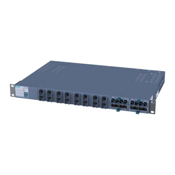
Siemens SCALANCE XR324-4M EEC Operating Instructions Manual
Scalance xr-300m eec series.
industrial ethernet switches
Hide thumbs
Also See for SCALANCE XR324-4M EEC:
- Operating instructions manual (322 pages) ,
- Operating instructions manual (314 pages) ,
- Compact operating instructions (84 pages)
Table of Contents
Advertisement
SCALANCE XR-300M EEC
SIMATIC NET
Industrial Ethernet switches
SCALANCE XR-300M EEC
Operating Instructions
11/2015
A5E02661176-09
___________________
Introduction
___________________
Safety notes
___________________
Description
___________________
Assembling
___________________
Connecting
___________________
Technical data
___________________
Dimension drawings
___________________
Approvals
1
2
3
4
5
6
7
8
Advertisement
Table of Contents

Related Manuals for Siemens SCALANCE XR324-4M EEC


Summary of Contents for Siemens SCALANCE XR324-4M EEC
- Page 1 ___________________ SCALANCE XR-300M EEC Introduction ___________________ Safety notes ___________________ SIMATIC NET Description ___________________ Assembling Industrial Ethernet switches SCALANCE XR-300M EEC ___________________ Connecting ___________________ Technical data Operating Instructions ___________________ Dimension drawings ___________________ Approvals 11/2015 A5E02661176-09...
-
Page 2: Legal Information
Note the following: WARNING Siemens products may only be used for the applications described in the catalog and in the relevant technical documentation. If products and components from other manufacturers are used, these must be recommended or approved by Siemens. Proper transport, storage, installation, assembly, commissioning, operation and maintenance are required to ensure that the products operate safely and without any problems. -
Page 3: Table Of Contents
Important notes 100 to 240 VAC / 60 to 250 VDC ..............12 Description ............................13 Unpacking and checking ......................13 Components of the XR-300M EEC product ................14 Product characteristics of the SCALANCE XR324-4M EEC ..........15 The SET / SELECT button ...................... 16 LED display ..........................17 C-PLUG ..........................21 3.6.1... - Page 4 Table of contents 5.4.3 Connecting devices with 100 to 240 V AC power supply ............43 5.4.3.1 100 ... 240 VAC - XR-300M EEC product group ..............43 5.4.3.2 Notes on the power supply 100 to 240 VAC ................43 5.4.3.3 Connecting the 100 to 240 VAC power supply ..............
-
Page 5: Introduction
Introduction Introduction to the XR-300M EEC Purpose of the Operating Instructions (compact) These operating instructions (compact) contain information with which you will be able to install and connect up a device of the SCALANCE X-300 product line. Validity of these Operating Instructions (compact) These Operating Instructions (compact) are valid for the product group XR-300M EEC of the SCALANCE X-300 product line (see product overview). -
Page 6: Xr-300M Eec Product Group
Introduction 1.2 XR-300M EEC product group XR-300M EEC product group Device Properties Order number XR324-4M EEC 1 x 24 to 48 VDC 6GK5 324-4GG00-1ER2 LEDs, connector data cable outlet on front Connector power supply and diagnostics port at rear 2 x 24 to 48 VDC 6GK5 324-4GG00-2ER2 LEDs, connector data cable outlet on front Connector power supply and diagnostics port at rear... -
Page 7: Type Designations
Introduction 1.3 Type designations Type designations Structure of the type designation The type designation of an IE Switch X-300 is made up of several parts that have the following meaning: Interfaces of devices without optical ports: Interface Property Electrical RJ-45 port for 10/100 Mbps. Electrical RJ-45 port for 10/100 Mbps and 10/100/1000 Mbps. - Page 8 Introduction 1.3 Type designations SCALANCE XR-300M EEC Operating Instructions, 11/2015, A5E02661176-09...
-
Page 9: Safety Notes
Safety notes Important notes on using the SCALANCE X-300 product family Safety notices on the use of the device The following safety notices must be adhered to when setting up and operating the device and during all associated work such as installation, connecting up, replacing or opening the device. - Page 10 Safety notes 2.1 Important notes on using the SCALANCE X-300 product family WARNING Replacing components EXPLOSION HAZARD SUBSTITUTION OF COMPONENTS MAY IMPAIR SUITABILITY FOR CLASS I, DIVISION 2 OR ZONE 2. WARNING Requirements for the cabinet/enclosure When used in hazardous environments corresponding to Class I, Division 2 or Class I, Zone 2, the device must be installed in a cabinet or a suitable enclosure.
-
Page 11: Important Notes On Using The Device In Hazardous Areas
Safety notes 2.2 Important notes on using the device in hazardous areas Important notes on using the device in hazardous areas WARNING WARNING - EXPLOSION HAZARD - DO NOT DISCONNECT WHILE CIRCUIT IS LIVE UNLESS AREA IS KNOWN TO BE NON-HAZARDOUS. -
Page 12: Important Notes 100 To 240 Vac / 60 To 250 Vdc
Safety notes 2.3 Important notes 100 to 240 VAC / 60 to 250 VDC Important notes 100 to 240 VAC / 60 to 250 VDC Note on devices with power supply 100 to 240 VAC / 60 to 250 VDC DANGER Danger from line voltage The supply voltage for the devices listed is 100 to 240 VAC and 60 to 250 VDC. -
Page 13: Description
Description Unpacking and checking Unpacking, checking WARNING Do not use any parts that show evidence of damage If you use damaged parts, there is no guarantee that the device will function according to the specification. If you use damaged parts, this can lead to the following problems: •... -
Page 14: Components Of The Xr-300M Eec Product
Description 3.2 Components of the XR-300M EEC product Components of the XR-300M EEC product Note • When shipped, all devices have a C-PLUG exchangeable medium. • When shipped, the slots for the media modules have a dummy cover fitted. • Labels to identify the installed MM900 media modules are supplied with the modular devices. -
Page 15: Product Characteristics Of The Scalance Xr324-4M Eec
CAUTION Use only approved media modules If you use media modules that are not approved by Siemens AG, there is no guarantee that the device will function according to the specification. If you use unapproved media modules, this can lead to the following problems: •... -
Page 16: The Set / Select Button
Description 3.4 The SET / SELECT button The SET / SELECT button The SET/SELECT button is located on the top of the housing of devices of the X-300 EEC series. On all other devices, this button is on the front panel of the housing beside the LED display. -
Page 17: Led Display
Description 3.5 LED display LED display The "RM" LED for the "redundancy manager" function The "RM" LED indicates whether or not the device is operating in the role of redundancy manager and whether or not the ring is operating error-free. LED color LED status Meaning... - Page 18 Description 3.5 LED display The "DM" LED for the display mode The "DM" LED (Display Mode) indicates which of the four display modes A, B, C or D is currently active. The meaning of the L1, L2 and P1, P2, ... LEDs depends on the display mode.
- Page 19 Description 3.5 LED display Meaning in display mode D Color Status Meaning L1 / L2 Power supply L1 / L2 is not monitored. If L1 / L2 falls below 17 V * , the signaling contact does not respond. green Power supply L1 / L2 is monitored.
- Page 20 Description 3.5 LED display LED color LED status Meaning yellow flashes / lit Receiving data at port. With SCALANCE X-300 devices, both the receipt and the sending of data is indicated for the optical gigabit ports. Meaning in display mode B LED color LED status Meaning...
-
Page 21: C-Plug
Description 3.6 C-PLUG C-PLUG 3.6.1 Area of application and function of the C-PLUG Area of application The C-PLUG (configuration plug) that ships with the product is an exchangeable memory medium for storing the configuration data of the device. The device can also be operated without a C-PLUG. -
Page 22: Removal And Insertion Of The C-Plug (Rack Devices)
Description 3.6 C-PLUG 3.6.2 Removal and insertion of the C-PLUG (rack devices) NOTICE A C-PLUG may only be removed or inserted when the device is turned off. Position of the C-PLUG with rack devices With rack devices, the slot is below a cover on the right-hand side of the housing. -
Page 23: Assembling
Assembling Notes on installation WARNING If a device is operated in an ambient temperature of more than 50 °C, the temperature of the device housing may be higher than 70 °C. The device must therefore be installed so that it is only accessible to service personnel or users that are aware of the reason for restricted access and the required safety measures at an ambient temperature higher than 50 ℃. -
Page 24: 19" Rack Mounting - Xr-300M Eec Product Group
Assembling 4.2 19" rack mounting - XR-300M EEC product group 19" rack mounting - XR-300M EEC product group WARNING Danger of injury by falling objects If you do not use the supplied mounting brackets for 19"rack installation, it is not possible to install the device correctly. - Page 25 The C-PLUG is on the right behind a protective panel se- • cured with screws. (For more detailed information, refer to the section on the C- SCALANCE XR324-4M EEC PLUG in the X-300 operating instructions.) The ventilation grilles are on the top, bottom and sides of the •...
- Page 26 - Installing media modules in a slot - Installing an SFP in an SFP media module. SCALANCE XR324-4M EEC Insert the rack device in the 19" cabinet and hold the rack device at the required height. Make sure that noth- ing is obstructing air from entering the ventilation grilles.
-
Page 27: Installation Of Modular Devices
NOTICE Use only approved media modules If you use media modules that are not approved by Siemens AG, there is no guarantee that the device will function according to the specification. If you use unapproved media modules, this can lead to the following problems: •... - Page 28 Assembling 4.3 Installation of modular devices CAUTION Remember the orientation of media modules. On modular devices, there are always two module slots arranged opposite each other. Remember the correct orientation when installing MM900 media modules. Example: • Install the first media module in slot 1. •...
- Page 29 Assembling 4.3 Installation of modular devices Note Slot number With modular devices, the MM900 media modules must be given a slot number. The slot number labels are supplied with the modular devices. Installing a media module The media module is inserted with the handle pulled out. When the handle is inserted, the media module is locked in the device.
- Page 30 Assembling 4.3 Installation of modular devices Place the media module in the guide rails of the device slot. The media module is correctly installed when it clips easily into the device. Push the handle back into the media module. This locks the media module in the device.
-
Page 31: Sfp Installation In Sfp Media Module
NOTICE Use only approved SFPs If you use SFPs that are not approved by Siemens AG, there is no guarantee that the device will function according to the specification. If you use unapproved SFPs, this can lead to the following problems: •... -
Page 32: Removing An Sfp
Assembling 4.3 Installation of modular devices Select the required SFP media module in the slot of the device. (Example: X-308-2M, slot 2) Insert the SFP with the clip closed in the SFP media module. Notice: Closing the clip after insertion does not lock the device in the rack. -
Page 33: Connecting
Connecting WARNING Before connecting up and commissioning the device, read the information in the section Safety notes (Page 9) NOTICE Failure of the data traffic due to contamination of optical plug-in connections Optical sockets and plugs are sensitive to contamination of the end face. Contamination can lead to the failure of the optical transmission network. - Page 34 Connecting 5.1 Connecting ground (EEC) Protective ground When the device is operated with multirange power supply unit 100 to 240 VAC / 60 to 250 VDC, the protective ground is connected in addition to the functional ground. CAUTION Danger from line voltage Grounding simply via the housing is inadequate.
-
Page 35: Signaling Contact
Connecting 5.2 Signaling contact Signaling contact The signaling contact (relay contact) is a floating switch with which error/fault states can be signaled by breaking the contact. Error indication ● The signaling by the signaling contact is synchronized with the fault LED, in other words, all errors displayed by this LED (freely configurable) are also signaled on the signaling contact. -
Page 36: Signaling Contact 100 To 240 Vac / 60 To 250 Vdc
Connecting 5.2 Signaling contact 5.2.2 Signaling contact 100 to 240 VAC / 60 to 250 VDC WARNING Danger from line voltage The supply voltage for the devices listed is 100 to 240 VAC and 60 to 250 VDC. This device can only function correctly and safely if it is transported, stored, set up, and installed correctly, and operated and maintained as recommended. -
Page 37: Diagnostics Port
Connecting 5.3 Diagnostics port To wire up the signaling contact, use a copper cable of category 18-8 AWG or cable with a cross-section of 0.75 to 6 mm². NOTICE Securing cables with dangerous voltage Make sure that the connector cannot be released accidentally by pulling on the connecting cable. - Page 38 Connecting 5.3 Diagnostics port Pin assignment The following table shows the pin assignment of the RJ-11 plug and the D sub female connector: Figure 5-1 RJ-11 jack (schematic) RJ-11 plug D-sub 9-pin, female Assignment Assignment n. c. n. c. n. c. RD (Receive Data) TD (Transmit Data) TD (Transmit Data)
-
Page 39: Power Supply
Connecting 5.4 Power supply Power supply 5.4.1 Power supply for the X-300EEC / XR-300M EEC Power supply of the IE switches X300 EEC / XR300M EEC WARNING Danger to life: 100 ... 240 V / 60 to 250 VDC Please note that the IE switches X300EEC / XR300M EEC can have a 100 to 240 VAC / 60 to 250 VDC - or a 24 to 48 VDC power supply. -
Page 40: Connecting Devices With 24 V Dc Power Supply
Connecting 5.4 Power supply 5.4.2 Connecting devices with 24 V DC power supply Table 5- 3 24 to 48 VDC safety extra-low voltage overview Device Device version 24 V safety extra-low voltage (power supply) (SELV) can be connected redundantly XR324-4M EEC 1 x 24 to 48 VDC ●... -
Page 41: Connecting A Redundant Power Supply To The Xr300-Eec
Connecting 5.4 Power supply Connecting to the power supply (SELV) ● The power supply is connected using a 4-pin plug-in terminal block. ● The power supply can be connected redundantly. Both inputs are isolated. There is no distribution of load. When a redundant power supply is used, the power supply unit with the higher output voltage supplies the IE Switch X-300 alone. - Page 42 Connecting 5.4 Power supply Connecting a redundant power supply to 1 power supply unit Use "PS1" to connect the power supply of the terminal block. Figure 5-2 Assignment of the LED display to the pins for redundant power supply with devices with one power supply unit Figure 5-3 Assignment of the LED display to the pins for redundant power supply with devices with...
-
Page 43: Scalance Xr-300M Eec Operating Instructions, 11/2015, A5E02661176-09
Connecting 5.4 Power supply ● If the power supply fails at pins L1/M1, this is indicated by LED L1. ● If the power supply fails at pins L2/M2, this is indicated by LED L2. It would also be possible to use the L1/M1 pins of the right terminal block. In this case, however, identification of the terminal block involved from the LED display is not immediately obvious. -
Page 44: Connecting The 100 To 240 Vac Power Supply
Connecting 5.4 Power supply 5.4.3.3 Connecting the 100 to 240 VAC power supply Power supply 100 to 240 VAC / 60 to 250 VDC The switch is available in the following versions for power supply with the multirange power supply unit 100 to 240 VAC / 60 to 250 VDC: ●... - Page 45 Connecting 5.4 Power supply Table 5- 6 Pin assignment at terminal block 100 to 240 VAC / 60 to 250 VDC for the power supply Pin number Assignment Pin 1 L (100 to 240 V) Pin 2 Pin 3 FE (functional earth) To wire up the power connector, use a copper cable of category 18-8 AWG or cable with a cross-section of 0.75 to 6 mm².
- Page 46 Connecting 5.4 Power supply SCALANCE XR-300M EEC Operating Instructions, 11/2015, A5E02661176-09...
-
Page 47: Technical Data
Technical data Construction, installation and environmental conditions Table 6- 1 Construction Device Device version Dimensions (W x H x Weight Degree of (power supply) protection XR324-4M 1 x 24 to 48 VDC 483 × 44 × 305 mm 6500 g IP20 2 x 24 to 48 VDC 483 ×... - Page 48 Technical data 6.1 Construction, installation and environmental conditions Media module Installation Operating temperature direction MM992-2CUC (C) Vertical -40 °C to +50 ℃ MM992-2CU MM992-2M12 (C) MM992-2VD MM991-2 MM991-2FM MM991-2LD MM991-2 (SC) MM991-2LD (SC) MM992-2 MM992-2 (C) MM992-2LD MM991-2LH+ (SC) Horizontal Maximum 2 modules in slots 3 and 4: MM992-2LH -40 °C to +60 °C...
-
Page 49: Connectors And Electrical Data
Technical data 6.2 Connectors and electrical data Connectors and electrical data Table 6- 5 Connection for end devices or network components Max. number 24 ports Electrical 16 x RJ-45 jacks 10/100/1000 Mbps Media module slots 4 x modular (2 ports per slot) 12 x modular (2 ports per slot) Transmitter output (optical) - Page 50 Technical data 6.2 Connectors and electrical data Table 6- 8 Electrical data: Overcurrent protection Device version Overcurrent protection of the power supply Non-replaceable fuse (power supply) 1 x 24 to 48 VDC 1 x T2H / 250 V 2 x 24 to 48 VDC 2 x T2H / 250 V 1 x 100 to 240 VAC / 60 to 250 VDC 1 x T2H / 250 V (AC)
-
Page 51: Cable Lengths
Technical data 6.3 Cable lengths Cable lengths Table 6- 12 Permitted cable lengths (copper cable - Fast Ethernet) Cable type Accessory (plug, outlet, Permitted cable length TP cord) IE TP torsion cable with IE FC Outlet RJ-45 0 to 45 m + 10 m TP cord + 10 m TP cord with IE FC RJ-45 Plug 180... -
Page 52: Block Architecture
Technical data 6.4 Block architecture Block architecture Block architecture with SCALANCE XR-300 devices The XR324-12M and XR324-4M handle the Ethernet frame traffic of the 24 ports with the aid of three switch blocks. ● The three switch blocks are connected in series (block 1 via block 2 to block 3) ●... -
Page 53: Other Properties
Technical data 6.5 Other properties Other properties Table 6- 14 Switching properties Max. number of learnable addresses 8000 Aging time 30 sec Switching technique Store and forward Latency 5 μs Table 6- 15 Reconfiguration times for redundancy mechanisms Redundancy mechanism Reconfiguration times 300 ms Standby link... - Page 54 Technical data 6.5 Other properties Number of frames per second At a frame length of At 100 Mbps At 1000 Mbps 23496 234962 512 bytes 11973 119732 1024 bytes 9615 96154 1280 bytes 8127 81274 1518 bytes Note The following applies to IE Switches X-300: The number of IE Switches X-300 connected in a line influences the frame delay time.
-
Page 55: Dimension Drawings
Dimension drawings XR-300M EEC dimension drawings Figure 7-1 Housing front and rear Figure 7-2 Top of the housing SCALANCE XR-300M EEC Operating Instructions, 11/2015, A5E02661176-09... - Page 56 Dimension drawings 7.1 XR-300M EEC dimension drawings SCALANCE XR-300M EEC Operating Instructions, 11/2015, A5E02661176-09...
-
Page 57: Approvals
Approvals XR-300M EEC approvals, certificates Approvals issued Note Issued approvals on the type plate of the device The specified approvals apply only when the corresponding mark is printed on the product. You can check which of the following approvals have been granted for your product by the markings on the type plate. - Page 58 (http://support.automation.siemens.com/WW/view/en/27069465)", in "Further documentation". – "EMC Installation Guidelines" configuration manual ID = 60612658 (http://support.automation.siemens.com/WW/view/en/60612658) ● Working on the device To protect the device from electrostatic discharge, personnel must first discharge any electrostatic charge from their body before touching the device.
- Page 59 Area". You will find this document • on the data medium that ships with some devices. • on the Internet pages of Siemens Industry Online Support (http://support.automation.siemens.com/WW/view/en). Enter the document identification number C234 as the search term. SIMATIC NET products meet the requirements of the EC directive:94/9/EC "Equipment and Protective Devices for Use in Potentially Explosive Atmospheres".
- Page 60 Approvals 8.1 XR-300M EEC approvals, certificates IECEx The SIMATIC NET products meet the requirements of explosion protection according to IECEx. IECEx classification: Ex nA IIC T4 Gc DEK 14.0025X The products meet the requirements of the following standards: ● IEC 60079-15 : 2010 (Explosive atmospheres - Part 15: Equipment protection by type of protection "n"...
- Page 61 Approvals 8.1 XR-300M EEC approvals, certificates cULus Approval for Information Technology Equipment cULus Listed I. T. E. Underwriters Laboratories Inc. complying with ● UL 60950-1 (Information Technology Equipment) ● CSA C22.2 No. 60950-1-03 Report no. E115352 Note Only variants with 24 VDC power supply meet the requirements of this approval. cULus approval for industrial control equipment cULus Listed IND.
-
Page 62: Xr-300M Eec Declaration Of Conformity
XR-300M EEC declaration of conformity Declaration of conformity You will find the EC Declaration of Conformity for these products on the Internet at the following address: http://support.automation.siemens.com/WW/view/en/67218486 (http://support.automation.siemens.com/WW/view/en/67218486) --> Entry list --> Entry type "Certificates" --> Certificate type "Declaration of Conformity"... -
Page 63: Overview Of Xr-300M Eec Approvals
Approvals 8.3 Overview of XR-300M EEC approvals Overview of XR-300M EEC approvals Note The 24 to 48 V variants do not have an E1 approval. The 100 to 240 V variants have C-Tick and CE approvals, are only UL508 listed, have no UL hazloc, FM or ATEX. -
Page 64: Xr-300M Eec Mechanical Stability (In Operation)
Approvals 8.4 XR-300M EEC mechanical stability (in operation) XR-300M EEC mechanical stability (in operation) The devices of the SCALANCE XR-300M EEC product group meet the following standards (prerequisite: rack mounted with 4 securing points): ● IEC 60068-2-6 (vibrations during transportation and operation) Test parameters: 5 –... -
Page 65: Index
Index Hazardous area, 9 Power supply Redundancy, 44 Redundancy Power supply, 44 Safety notices, 9 System manual, 58 SCALANCE XR-300M EEC Operating Instructions, 11/2015, A5E02661176-09... - Page 66 Index SCALANCE XR-300M EEC Operating Instructions, 11/2015, A5E02661176-09...
Need help?
Do you have a question about the SCALANCE XR324-4M EEC and is the answer not in the manual?
Questions and answers